

Page 1
EINBAUANLEITUNG PRINT LCA11 / LCB 11
Achtung! Dieser Umbau darf nur von geschultem Fachpersonal
durchgeführt werden! Vor Öffnen des Gerätes, Netzschalter in
Stellung „0“ schalten und Netzstecker ziehen!
Hinweis! Beachten Sie die Sicherheitsvorschriften in der Bedienungsanleitung; insbesondere den Teil „Sicherheitstechnische Inspektion“.
LIEFERUMFANG BAUGRUPPE „PRINT LCA11“
4,070,722,Z / „PRINT LCB11“ 4,070,724,Z
Pos. Bezeichnung Stück
Print LCA11 / Print LCB 11............................................................. 1
Schrauben M4x14 (TX20)................................................................ 2
Tellerfedern ....................................................................................... 2
Kabelbinder ....................................................................................... 2
GEHÄUSE ÖFFNEN
- Schraube 5x25 (TX20) an der Gehäusevorderseite lösen (Abb.1)
- Schraube 5x25 (TX20)
- Gehäusemantel vorsichtig anheben und „Erdleiter Gehäuse“ abstekken (Abb.2)
- Gehäuseversteifung entfernen (Abb.3)
- Printisolation entfernen (Abb.3)
an der Gehäuserückseite lösen (Abb.2)
PRINT LCA11 / LCB11 AUSBAUEN
- „Erdleiter Print LCA11/LCB11“ an Trafohalterung abstecken (Abb.4)
- Am Netzschalter „Netzleitungen Print LCA11“ abstecken (Abb.5)
- L (weiß) von 1A
- N (blau) von 2A
- 2-poligen Molexstecker am Print LCA11/LCB11 / X6 abstecken
(Abb.6)
- 6-poligen Molexstecker am Print LCA11/LCB11 / X7 abstecken
(Abb.6)
- Abdeckkappe vom „Einstellregler Schweißstrom“ abnehmen (Abb.7)
Hinweis! Beim Lösen der Befestigungsmutter für den „Einstellregler Schweißstrom“
- Befestigungsmutter des Einstellreglers
- Einstellregler abziehen (Abb.7)
Hinweis! Beim Lösen der Rundmutter
(Abb.9) festhalten.
- Rundmutter lösen und entfernen (Abb.8)
, Einstellregler festhalten.
mit Steckschlüssel (Schlüssel-
weite 7) lösen
(Abb.8), den Frontprint FPA11
PRINT LCA11 / LCB11 EINBAUEN
- „Schutzleiter Netzkabel“ an Trafohalterung abstecken (Abb.11)
- An der Luftleitfolie
Lüfter
aushängen (Abb.11)
- Luftleitfolie
- Kühlkörper mit Kontaktspray und nicht faserndem Tuch vorreinigen
(Abb.13)
- Am Kühlkörper Verunreinigungen bzw. Unebenheiten mit feinem Schleifpapier (Körnung P 500 oder feiner) beseitigen
- Kühlkörper mit Kontaktspray und nicht faserndem Tuch reinigen (Abb.13)
Hinweis! Beim Abziehen der Schutzfolie
LCA11/LCB11, die beschichtete Wärmeleitfolie
belassen (Abb.14).
- Schutzfolie
Hinweis! Beim Anklemmen der „Trafoleitungen Print LCA11/LCB11“,
braucht nicht auf eine bestimmte Polarität geachtet werden (Wechselstromleitungen).
- WAGO-Klemmen
Print LCA11/LCB11“ bis zum Anschlag einschieben (Abb.12)
- „Trafoleitungen Print LCA11/LCB11“ mittels Kabelbinder
binden (Abb.15)
Print LCA11:
- „Trafoleitungen Print LCA11“, mit WAGO-Klemmen
verstauen (Abb.15)
Print LCB11:
- „Trafoleitungen Print LCB11“, mit WAGO-Klemmen
verstauen (Abb.15a)
Hinweis! Beim Aufsetzen des Prints LCA11/LCB11 darauf achten, daß die
„Trafoleitungen Print LCA11/LCB11“ nicht zwischen Transistormodul und
Kühlkörper eingeklemmt werden.
Auf Sauberkeit achten! Verunreinigungen zwischen Transistormodul und
Kühlkörper beeinträchtigen die Wärmeübertragung.
- Print LCA11/LCB11 vorsichtig auf Kühlkörper legen (Abb.10)
Hinweis! Vor dem Ansetzen der Schrauben M4x14 (TX20)
Fixierung des Prints LCA11/LCB 11 auf dem Kühlkörper, die Tellerfedern
gemäß Abbildung auf die Schrauben M4x14 (TX20) aufschieben.
(Abb.16)
- Schrauben M4x14 (TX20) abwechselnd vorsichtig andrehen, bis ein
leichter Widerstand spürbar wird (Abb.10)
„Schutzleiter Netzkabel“ und Leitungen für den
entfernen (Abb.11)
vom Transistormodul am Print
auf dem Transistormodul
vom Transistormodul abziehen (Abb.14)
vollständig zusammendrücken und „Trafoleitungen
zusammen-
, gemäß Abbildung
, gemäß Abbildung
, zur
Hinweis! Beim Entnehmen des Frontprints FPA11
vorderseite, darauf achten, daß das Flachbandkabel nicht eingeklemmt,
geknickt oder auf Zug belastet wird (Abb.9).
- Frontprint FPA11 aus der Gehäusevorderseite nehmen (Abb.9)
- 2 Schrauben M4x14 (TX20)
lösen (Abb.10)
Hinweis! Beim Abnehmen des Prints LCA11/LCB11 darauf achten, daß
keine Kabel eingeklemmt, geknickt oder auf Zug belastet werden.
- Print LCA11/LCB11 vorsichtig vom Kühlkörper abnehmen (Abb.11)
Hinweis! Beim Abklemmen der „Trafoleitungen Print LCA11“, WAGOKlemmen vollständig zusammendrücken (Abb.11 und Abb.12).
- „Trafoleitungen Print LCA11/LCB11“ abklemmen (Abb.11 und Abb.12)
42,0410,0662 012002
, mit Tellerfedern, am Print LCA11/LCB11
aus der Gehäuse-
Hinweis! Vor dem Festschrauben der Schrauben M4x14 (TX20)
das Transistormodul lückenlos und eben auf dem Kühlkörper aufliegen.
- Schrauben M4x14 (TX20)
Hinweis! Beim Einsetzen der Luftleitfolie
„Trafoleitungen Print LCA11/LCB11“ von der Luftleitfolie
(Abb.11)
- Luftleitfolie
- An der Luftleitfolie „Schutzleiter Netzkabel“
einhängen (Abb.11)
- „Schutzleiter Netzkabel“ an Trafohalterung anstecken (Abb.11)
1
einsetzen (Abb.11)
mit 2 Nm festschrauben (Abb.10)
darauf achten, daß die
überdeckt werden
und Leitungen für den Lüfter
muß
Page 2
Hinweis! Bei der Montage des Frontprints FPA11
das Flachbandkabel
(Abb.17).
nicht den Kupferbügel zur - Buchse berührt
darauf achten, daß
- Frontprint FPA11
Hinweis! Bei der Fixierung des Frontprints FPA11
gerade ansetzen und vorsichtig andrehen. Dabei den Frontprint FPA11
festhalten (Abb.8).
- Rundmutter
- Einstellregler Schweißstrom positionsrichtig auf Welle aufsetzen
(Abb.7)
Hinweis! Befestigungsmutter für den Einstellregler Schweißstrom
vorsichtig festschrauben. Dabei den Einstellregler Schweißstrom festhalten.
- Befestigungsmutter des Einstellreglers Schweißstrom
schlüssel (Schlüsselweite 7) festschrauben (Abb.7)
- Abdeckkappe auf Einstellregler Schweißstrom
- 2-poligen Molexstecker
(Abb.6)
- 6-poligen Molexstecker
(Abb.6)
Hinweis! Wurde beim Ausbau des Prints LCA11/LCB11 der Kabelbinder
durchtrennt:
- Die Kabel für 2-poligen und 6-poligen Molexstecker, in der Nähe der
beiden Molexstecker, mittels Kabelbinder
in Gehäusevorderseite einsetzen (Abb.9)
, Rundmutter
anschrauben und leicht festziehen (Abb.8)
mit Steck-
aufsetzen
am Print LCA11/LCB11 / X6 anstecken
am Print LCA11/LCB11 / X7 anstecken
zusammenbinden (Abb.6)
- Am Netzschalter „Netzleitungen Print LCA11/LCB11“ anstecken (Abb.5)
- L (weiß)
- N (blau)
- „Erdleiter Print LCA11/LCB11“
an 1A
an 2A
an Trafohalterung anstecken (Abb.4)
GEHÄUSE SCHLIESSEN
- Printisolation einsetzen (Abb.3)
- Gehäuseversteifung
- „Erdleiter Gehäuse“
Hinweis! Vor dem Aufsetzen des Gehäusemantels auf korrekte Lage der
Printisolation
- Gehäusemantel aufsetzen (Abb.2)
- Schraube 5x25 (TX20)
- Schraube 5x25 (TX20) an der Gehäusevorderseite festschrauben
(Abb.1)
achten (Abb.3).
einsetzen (Abb.3)
am Gehäusemantel anstecken (Abb.2)
an der Gehäuserückseite festschrauben (Abb.2)
2
Page 3

INSTALLATION INSTRUCTIONS: LCA11 / LCB11 BOARD
Warning! This modification may only be performed by suitably
trained and skilled electricians! Before opening up the machine, shift
the mains switch to the "0" position and unplug the machine from the
mains!
N.B.! Follow the safety rules given in the Operating Instructions, especially
the section headed "Safety inspection".
SCOPE OF SUPPLY OF ASSEMBLY “LCA 11 BOARD”
4,070,722,Z / “LCB11 BOARD” 4,070,724,Z
Item Designation N° of items
LCA11 / LCB11 board ..................................................................... 1
Screws M4x14 (TX20) ..................................................................... 2
Cup springs ...................................................................................... 2
Cable binders ................................................................................... 2
REMOVING THE HOUSING
- Undo the 5x25 screw (TX20) on the front of the housing (Fig.1)
- Undo the 5x25 screw (TX20) on the back of the housing (Fig.2)
- Carefully lift the housing and unplug the “Housing earthing conductor”
(Fig.2)
- Remove the housing stiffening element (Fig.3)
- Remove the board insulation (Fig.3)
REMOVING THE LCA11 / LCB11 BOARD
- Unplug the “LCA11/LCB11 board earthing conductor” from the
transformer holder (Fig.4)
- Unplug the “LCA11/LCB11 board mains leads” from the mains switch
(Fig.5)
- L (white) from 1A
- N (blue) from 2A
- Unplug the 2-pole Molex plug from board LCA11/LCB11 / X6 (Fig.6)
- Unplug the 6-pole Molex plug
- Take off the cap from the “Welding-current setting dial” (Fig.7)
N.B.! When undoing the fixing-nut for the “Welding-current setting dial” ,
hold the setting dial firmly.
- Undo the fixing-nut of the setting dial
(width across = 7)
- Pull off the setting dial
N.B.! When undoing the round nut (Fig.8), hold the front board FPA11
(Fig.9) firmly.
- Undo the round nut and remove it (Fig.8)
N.B.! When removing the front board FPA11 from the front of the housing,
make sure that the ribbon cable is not pinched or kinked, or strained by being
pulled (Fig.9).
- Take the front board FPA11 out of the front of the housing (Fig.9)
- Unscrew the two M4x14 screws (TX20)
LCA11/LCB11 board (Fig.10)
N.B.! When removing the LCA11/LCB11 board, do not pinch or kink any
cables, or strain them by pulling them.
- Carefully detach the LCA11/LCB11 board from the heat sink (Fig.11)
N.B.! When disconnecting the “LCA11/LCB11 board transformer leads”,
press the WAGO connectors completely together (Fig.11 and Fig.12).
from board LCA11/LCB11 / X7 (Fig.6)
with a socket wrench
(Fig.7)
(with cup springs) from the
- Disconnect the “LCA11/LCB11 board transformer leads” (Fig.11 and
Fig.12)
FITTING THE LCA11 / LCB11 BOARD
- Unplug the “Mains cable PE conductor” from the transformer holder
(Fig.11)
- Detach the “Mains cable PE conductor”
air-guide film
- Remove the air-guide film
- Pre-clean the heat sink with contact spray and a non-linting cloth (Fig.13)
- Remove any contamination or unevenness from the heat sink with fine
abrasive paper (grain P 500 or finer)
- Clean the heat sink with contact spray and a non-linting cloth (Fig.13)
N.B.! When peeling the protective film
LCA11/LCB11 board, leave the coated heat-transfer film
module (Fig.14)
- Peel the protective film
N.B.! When connecting the “LCA11/LCB11 board transformer leads”, you
do not need to worry about the polarity (AC lines).
- Press the WAGO connectors completely together and push in the
“LCA11/LCB11 board transformer leads” as far as they will go (Fig.12)
- Tie the “LCA11/LCB11 board transformer leads” together using cable
binders
LCA11 board:
- Stow away the “LCA11 board transformer leads” (complete with WAGO
connectors)
LCB11 board:
- Stow away the “LCB11 board transformer leads” (complete with WAGO
connectors)
N.B.! When fitting the LCA11/LCB11 board in place, make sure that the
“LCA11/LCB11 board transformer leads” are not trapped between the
transistor module and the heat sink.
All parts must be kept clean! Any contamination between the transistor
module and the heat sink will impair the heat-transfer.
- Carefully place the LCA11/LCB11 board onto the heat sink (Fig.10)
N.B.! Before positioning the two M4x14 screws (TX20)
/LCB11 board onto the heat sink, push the cup springs
screws (TX20)
- Carefully turn the M4x14 screws (TX20)
feel slight resistance (Fig.10)
N.B.! Before you tighten the M4x14 screws (TX20)
must be lying completely flat on the heat sink, without any gaps.
- Tighten the M4x14 screws (TX20)
N.B.! When replacing the air-guide film
board transformer leads” are covered by the air-guide film
- Replace the air-guide film
- Attach the “Mains cable PE conductor”
air-guide film (Fig.11)
- Plug the “Mains cable PE conductor”
(Fig.11)
(Fig.11)
(Fig.11)
off the transistor module (Fig.14)
(Fig.15)
, as shown in the picture (Fig.15)
, as shown in the picture (Fig.15a)
as shown in the picture (Fig.16)
(Fig.11)
and the fan cables from the
off the transistor module on the
on the transistor
to fix the LCA11
onto the M4x14
alternately, until you start to
the transistor module
with a torque of 2 Nm (Fig.10)
, make sure that the “LCA11/LCB11
(Fig.11)
and the fan cables to the
onto the transformer holder
3
Page 4

N.B.! When mounting the front board FPA11
does not touch the copper bow leading to the -socket (Fig.17).
cable
, make sure that the ribbon
- Insert the front board FPA11
N.B.! When fixing the front board FPA11
straight, and turn it carefully, holding the front board FPA11 at the same
time (Fig.8).
- Screw on the round nut
- Hold the welding-current setting dial
the shaft (Fig.7)
N.B.! Carefully screw down the fixing nut for the welding-current setting
dial
. When doing this, hold the setting dial firmly.
- Screw down the fixing-nut of the welding-current setting dial
socket wrench (width across = 7) (Fig.7)
- Fit the cap back onto the welding-current setting dial
- Plug the 2-pole Molexstecker onto board LCA11/LCB11 / X6 (Fig.6)
- Plug the 6-pole Molexstecker onto board LCA11/LCB11 / X7 (Fig.6)
N.B.! If the cable binder was cut when the LCA11/LCB11 board was
removed:
- Use cable binders
Molex plugs. Position the cable binders near the Molex plugs (Fig.6).
- Plug the “LCA11/LCB11-board mains leads” onto the mains switch
(Fig.5)
- L (white)
- N (blue)
- Plug the “LCA11/LCB11-board earthing conductor”
mer holder (Fig.4)
to tie tigether the cables for the 2-pole and 6-pole
to 1A
to 2A
into the front of the housing (Fig.9)
, position the round nut
, tightening it gently (Fig.8)
in the right position and push it onto
with a
onto the transfor-
FITTING THE HOUSING
- Replace the board insulation (Fig.3)
- Insert the housing stiffening element
- Plug the “Housing earthing conductor”
N.B.! Before putting the housing back on, make sure that the board insulation
is in the correct position (Fig.3).
- Put the housing back on (Fig.2)
- Tighten the 5x25 screw (TX20)
- Tighten the 5x25 screw (TX20)
(Fig.3)
onto the housing (Fig.2)
on the backof the housing (Fig.2)
on the front of the housing (Fig.1)
4
Page 5

INSTRUCTIONS D’INSTALLATION PLAQUETTE À CIRCUITS IMPRIMÉS
LCA11 / LCB11
Attention! Cette modification ne doit être exécutée que par du
personnel technique expérimenté! Avant d’ouvrir l’appareil il faut
mettre l’interrupteur secteur en position "0", et retirer la fiche secteur!
Note! Observez les instructions de sécurité dans le mode d'emploi; en
particulier la partie "inspection techique de sécurité".
VOLUME DE LIVRAISON BLOC "PLAQUETTE À
CIRCUITS IMPRIMÉS LCA11“ 4,070,722,Z /
"PLAQUETTE À CIRCUITS IMPRIMÉS LCB11“
4,070,724,Z
Pos. Désignation Pièces
Plaquette à circuits imprimés LCA11 / LCB11 ............................... 1
Vis M4x14 (TX20) ............................................................................ 2
Ressorts à disques .......................................................................... 2
Attaches de câble ............................................................................. 2
DÉMONTER L'ENVELOPPE DU BOÎTIER
- Desserrer la vis 5x25 (TX20) sur le front du boîtier (fig.1)
- Desserrer la vis 5x25 (TX20)
- Soulever avec précaution l'enveloppe du boîtieret débrancher le "fil de
terre boîtier" (fig.2)
- Enlever le renforcement du boîtier (fig.3)
- Enlever l'isolation de la plaque à circuits imprimés (fig.3)
sur le dos du boîtier (fig.2)
- Enlever avec précaution la plaquette à circuits imprimés LCA11/LCB11
du corps refroidisseur (fig.11)
Note! Lors du débranchement des "lignes de transfo plaquette à circuits
imprimes LCA11/LCB11" il faut comprimer complètement les bornes WAGO
(fig.11 et fig. 12).
- Débrancher les "lignes de transfo plaquette à circuits imprimes LCA11/
LCB11“ (fig.11 et fig. 12)
INSTALLER LA PLAQUETE À CIRCUITS IMPRIMÉS
LCA11/LCB11
- Débrancher la "terre câble de secteur " sur le support pour tansfo (fig.11)
- Décrocher à la feuille de guidage d'air
et les lignes pour le ventilateur (fig.11)
- Enlever la feuille de guidage d'air
- Nettoyer préliminairement le cors de refroidissement par u n spray de
contact et un torchon qui ne s'effile pas (fig. 13).
- Enlever des impuretés ou des rugosités sur le corps de refroidissement
par du papier - émeri fin (granulation P500 ou plus fin)
- Nettoyer le corps de refroidissement par du spray de contact et un torchon
qui ne s'effile pas (fig. 13).
Note! En enlevant la feuille de protection
plaquette à circuits imprimés LCA11/LCB11 il faut laisser la feuille thermoconductrice plaquée
- Enlever la feuille protectrice
sur le module à transistor (fig.14).
du module à transitor (fig.14)
la "terre de câble secteur"
(fig.11)
du module de transistor sur la
DÉMONTER LA PLAQUETTE À CIRCUITS IMPRIMÉS
LCA11 / LCB11
- Débrancher le "fil de terre plaquette à circuits imprimés LCA11/LCB11"
sur le support pour le transfo (fig.4)
- Débrancher les "lignes de réseau plaquette à circuit imprimé LCA11/
LCB11" sur l'interrupteur de réseau (fig.5)
- L (blanc) de 1A
- N (bleu) de 2A
- Débrancher la fiche Molex à 2 broches sur la plaquette à circuits
imprimes LCA11/LCB11 / X6 (fig.6)
- Débrancher la fiche Molex à 6 broches
imprimes LCA11/LCB11 / X7 (fig.6)
- Enlever la chape du "régulateur de courant de soudage" (fig.7)
Note! En desserrant l'écroou de fixation pour le "régulateur de courant de
soudage" il faut arrêter le régulateur .
- Desserrer l'écrou de fix. du régulateur
- Enlever le réegulateur
Note! En desserrant l'écrou rond (fig.8) il faut retenir la paquette à circuits
imprimé sur le front FPA11 (fig. 9).
- Desserrer l'écrou rond
Note! Lors de l'enlèvement de la plaquette à circuits imprimés de front FPA11
du front du boîtier il faut veiller à ce que le câble à ruban ne soit pas serré,
plié ou soumis à une charge de traction (fig. 9).
- Enlever la plaquette à circuits imprimés frontale FPA11
boîtier (fig.9)
- Desserrer 2 vis M4x14 (TX20) , avec ressorts à disques sur la plaquette
à circuits imprimés LCA11/LCB11 (fig.10)
Note! Lors de l'enlèvement de la plaqu. à circuits imprimes LCA11/LCB11
il faut veiller à ne pas serrer aucunes câbles, les plier ou les soumettre à une
charge de traction. Lors de l'enlèv. de la plaqu. à circuits imprimés LCA11/
LCB11 il faut veiller à ne pas coincer, plier ou soumettre à une charge de
traction aucun câble.
(fig.7)
et l'éliminer (fig.8)
sur la plaquette à circuits
moy. clé à douille (ouverture 7)
du front du
Note! En branchant les "lignes de transfo plaquette à circuits imprimés
LCA11/LCB11 il n'est pas nécessaire d'observer une polarité déterminée
(lignes de courant alternatif).
- Conprimer complètement les bornes WAGO et introduire les "lignes
transfo plaquette à circuits imprimés LCA11/LCB11" jusqu'à l'arrêt (fig.
12)
- Attacher les "lignes transfo de la plaquette à circuits imprimés LCA11/
LCB11" moyennant les attaches de câbles
Plaquette à circuits imprimés LCA11:
- Loger les "lignes transfo de la plaquette à circuits imprimés LCA11" aved
les bornes WAGO
Plaquette à circuits imprimés LCB11:
- Loger les "lignes transfo de la plaquette à circuits imprimés LCB11" aved
les bornes WAGO
Note! Lors du montage de la plaquette à circuits imprimés LCA 11/LCB11
il faut veiller à ce que les "lignes transfo de la plaquette à circuits imprimés
LCA11/LCB11" ne soient pas serrées entre le module à transistor et le corps
de refroidissement.
Observez la propreté! Les impuretés entre le moodule á transiston et le corps
de refroidissement réduisent le transfert de chaleur.
- Mettre la plaquette à circuits imprimés LCA11/LCB11 avec précaution
sur le corps de refroidissement (fig.10)
Note! Avant de monter les vis M4x14 (TX20)
circuits imprimés LCA11/LCB11 sur le corps refroidisseur il faut enfiler les
ressorts à disques
- Serrer alternativement et avec pécaution les vis M4x14 (TX20)
sentir une légère résistance (fig. 10).
Note! Avant de serrer les vis M4x14 (TX20) le module à transistor doit
être posé complètement et de manière plane sur le corps de refroidissement.
- Serrer les vis M4x14 (TX20)
5
suivant la figure (fig.15)
suivant la figure (fig.15a)
suivant la figue sur ls vis M4 x 14 (TX20) (fig.16).
avec 2 Nm (fig.10)
(fig.15)
pour fixer la plaquette à
jusqu'à
Page 6

Note! Lors du montage de la feuille de guidage d'air
les "lignes de transfo plaquette à circuits imprimés LCA11/LCB11" soient
recouvertes le la feuille de guidage d'air
(fig.11).
il faut veiller à ce que
- Monter la feuille de guidage d'air
- Encrocher le "fil de terre câble secteur"
sur la feuille de guidage d'air (fig.11)
- Brancher le "fil de terre câble secteur" sur le support pour transfo (fig.
11)
Note! Lors du montage de la plaquette à circuits imprimés frontale FPA11
il faut veiller à ce que le câble à ruban
en cuivre
- Monter la plaquette à circuits imprimés FPA11
(fig.9)
Note! Lors de la fixation de la plaquette à circuits imprimés frontale FPA11
il faut monter de manière droite l'écrou rond et le serrer avec précaution.
En faisant ceci il faut tenir la plaquette à circuits imprimés frontale FPA11
(fig.8).
- Visser et serrer légèrement l'écrou rond (fig.8)
- Monter le régulateur du courant de soudage
sur l'arbre (fig.7)
Note! Serrer avec précaution l'écrou de fixation du régulateur du courant
de soudage . En faisant ceci maintenir le régulateur de courant de soudage
.
- Serrer l'écrou de fixation du régulateur de courant de soudage
moyennant clé à pipe (ouverture 7) (fig.7)
- Monter la chape sur le régulateur de courant de soudage
- Brancher la fiche Molex à 2 broches sur la plaquette à circuits imprimés
LCA11/LCB11 / X6 (fig.6)
- Brancher la fiche Molex à 6 broches sur la plaquette à circuits imprimés
LCA11/LCB11 / X7 (fig.6)
vers la douille - (fig.17).
(fig.11)
et les lignes pour le ventilateur
ne soit pas en contact avec l'archet
dans le front de l'appareil
dans la position correcte
Note! Quand l'attache de câbles a été détachée lors du démontage de la
plaquette à circuits imprimés LCA11/LCB11:
- Attacher les câbles pour les fiches Molex à 2 broches et à 6 broches à
proximité des deux fiches Molex moyennant une attache de câbles
(fig.6)
- Brancher les "lignes de secteur plaquette à circuits imprimés LCA11/
LCB11" (fig. 5) sur l'interrupteur secteur
- L (blanc)
- N (bleu)
- Brancher le "fil de terre plaquette à circuits imprimés LCA11/LCB11“
sur le support pour transfo (fig.4)
sur 1A
sur 2A
MONTER L'ENVELOPPE DU BOÎTIER
- Monter l'isolation de la plaquette à circuits imprimés (fig.3)
- Monter le renforcement du boîtier (fig.3)
- Brancher le "fil de terre boîtier"
Note! Avant du montage de l'enveloppe de boîtier, il faut veiller à ce que
l’isolation de la plaquette à circuits imprimés est à la position exact (fig.3).
- Monter l'enveloppe de boîtier (fig.2)
- Serrer la vis 5x25 (TX20)
- Serrer la vis 5x25 (TX20)
sur l'enveloppe de boîtier (fig.2)
sur le dos du boîtier (fig.2)
sur le front du boîtier (fig.1)
6
Page 7

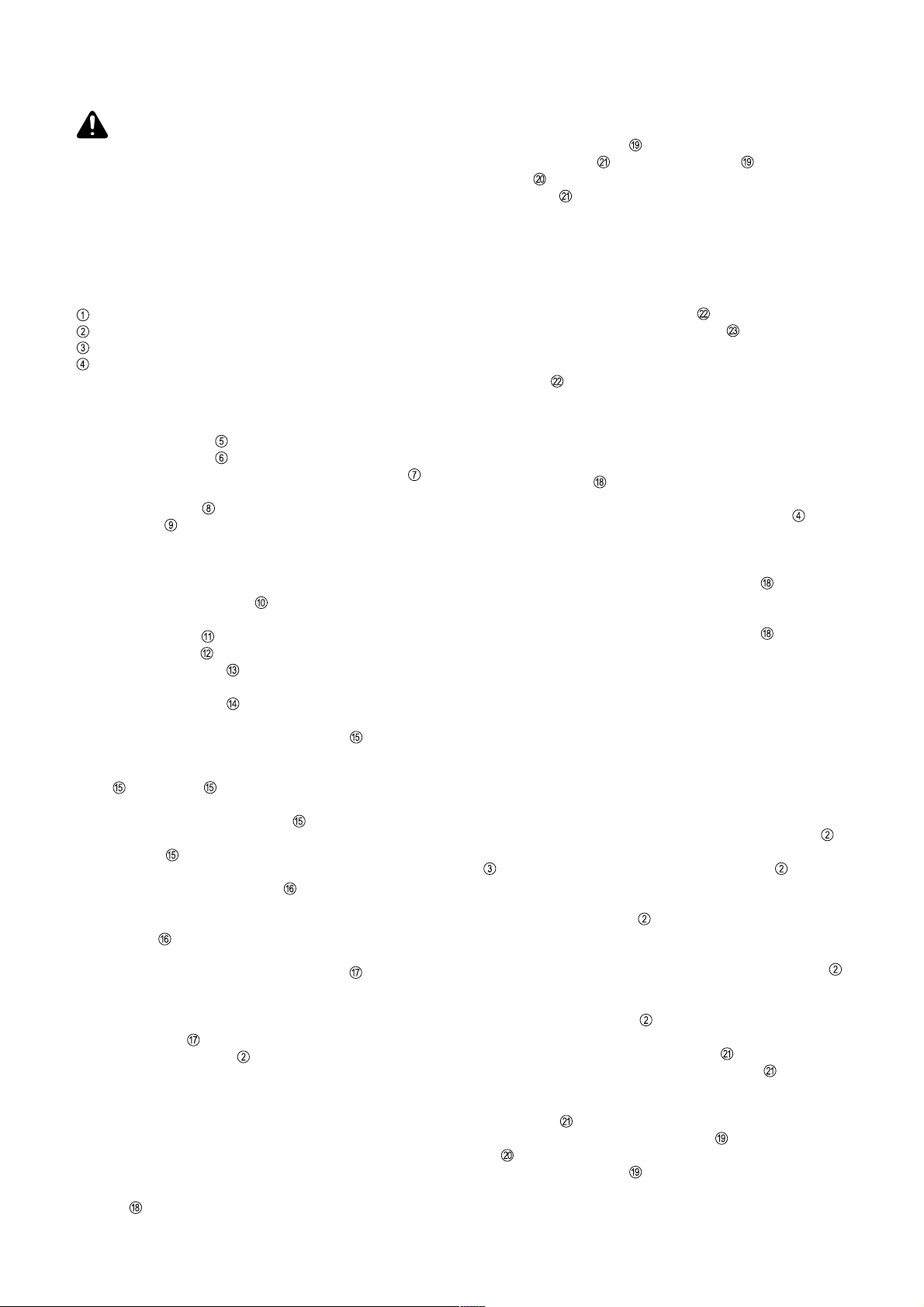
Abb.1 / Fig.1 Abb.2 / Fig.2
Abb.3 / Fig.3
Abb.5 / Fig.5
Abb.6 / Fig.6
Abb.4 / Fig.4
Abb.7 / Fig.7 Abb.8 / Fig.8
7
Page 8

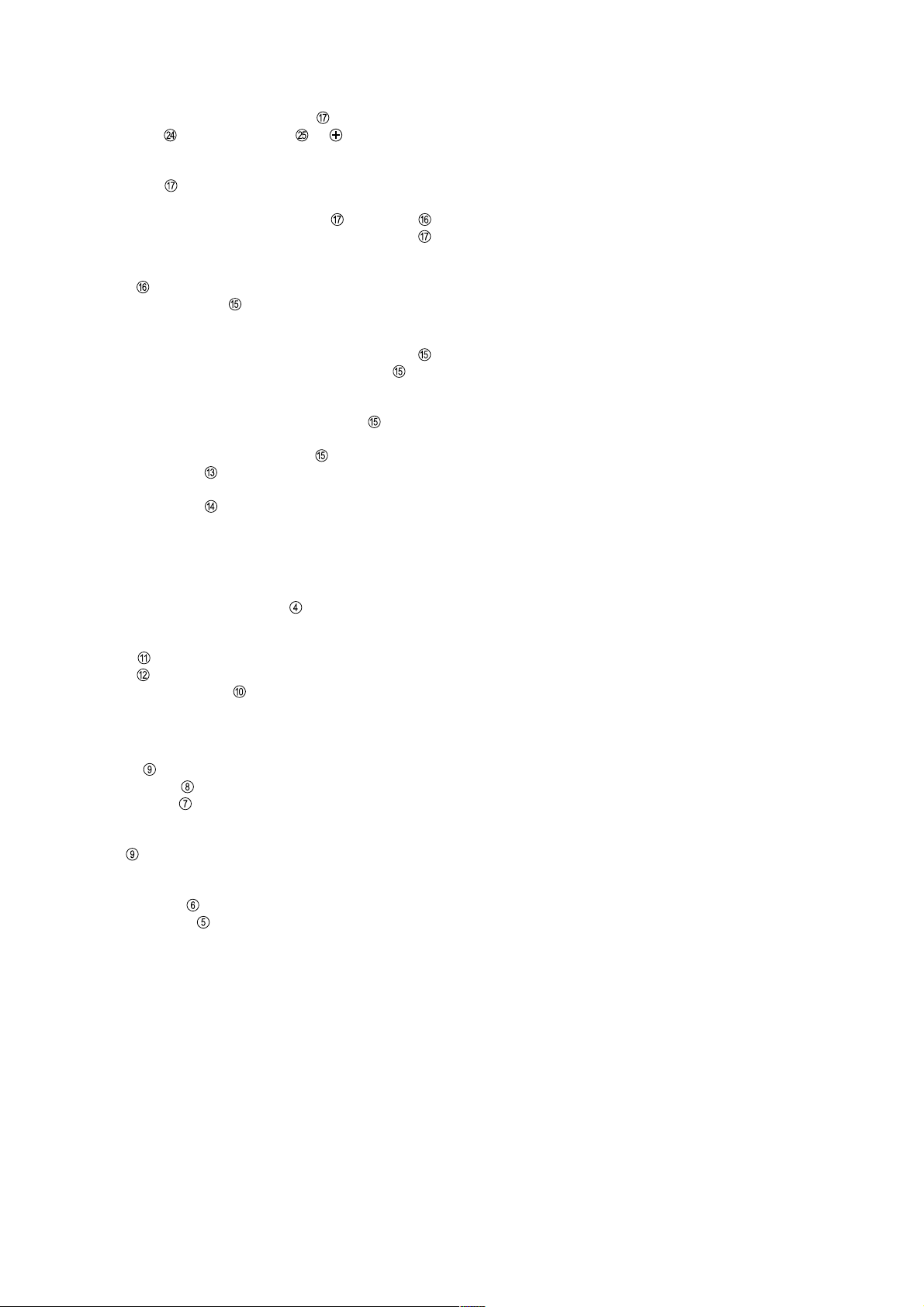
Abb.9 / Fig.9
Abb.10 / Fig.10
Abb.12 / Fig.12
Abb.13 / Fig.13
Abb.11 / Fig.11
Abb.14 / Fig.14
8
Page 9

Abb.15 / Fig.15
Abb.16 / Fig.16 Abb.17 / Fig.17
Abb.15a / Fig.15a
9
 Loading...