

Page 1

EINBAUANLEITUNG HF66
Achtung! Dieser Umbau darf nur von geschultem Fachpersonal durchgeführt werden! Vor Öffnen des Gerätes, Netzschalter
in Stellung „0“ schalten und Netzstecker ziehen!
Hinweis! Beachten Sie die Sicherheitsvorschriften in der Bedienungsanleitung; insbesondere den Teil „Sicherheitstechnische Inspektion“.
VORGEHENSWEISE
- rechtes Seitenteil der Stromquelle entfernen
- sämtliche Steckverbindungen am Print HF260 lösen
- Print HF260 entfernen
Hinweis! Ist bereits ein Print HF66 eingebaut, können Zwischenblech, Distanz und Eprom entsorgt werden.
- Vier Stück Printdistanzen aus dem Zwischenblech entfernen und entsorgen
- Kunststoffdistanzen am Montageblech des Print HF66 von der Unterseite durch die vier Bohrungen stecken und mit Kunststoffdistanzen fixieren
- 4-poligen Molexstecker A3-X1 am Print HF66, Molexbuchse X3 einsetzen
- Beide Flachstecker vom Zündübertrager an den Stiftkontakten X1+ und X1- polrichtig anstecken
- Eprom MWI 1V20 auf Print UTI 2A gegen mitgeliefertes Eprom MWI 2V10 austauschen
- rechtes Seitenteil der Stromquelle wieder montieren
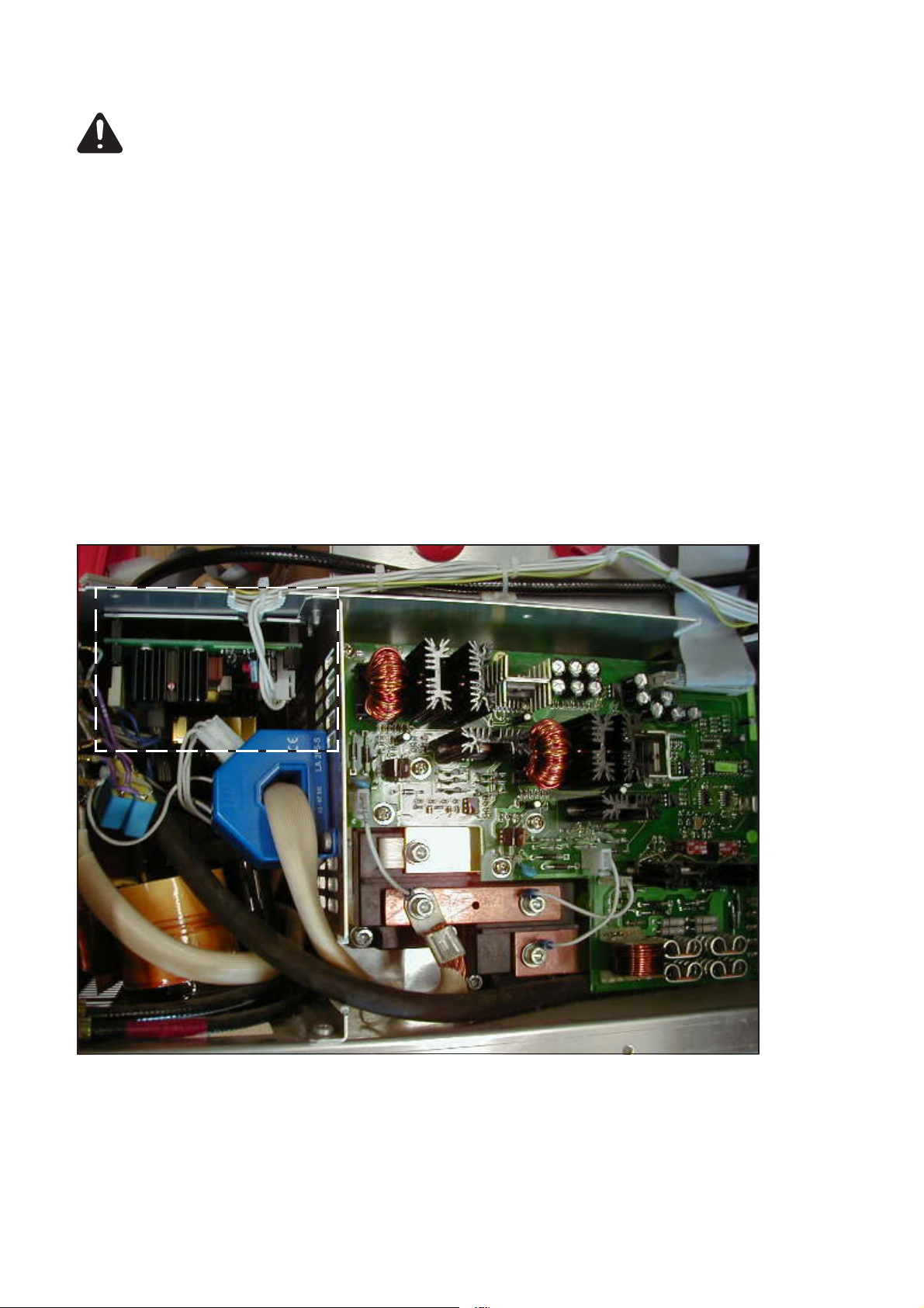
Print HF 66
Abb.1 Detailansicht
Text und Abbildungen entsprechen dem technischen Stand bei Drucklegung. Änderungen vorbehalten.
42,0410,0692 002-03072012
1
Page 2

INSTALLATION INSTRUCTIONS FOR HF66
Warning! This modification may only be performed by suitably trained and skilled electricians! Before opening up the
machine, shift the mains switch to the "0" position and unplug from the mains!
N.B! Follow the safety rules given in the Operating Instructions, especially the section headed "Safety inspection".
HOW TO INSTALL
- Take off the right-hand side panel of the power source
- Undo all plug-in connections on the HF260 printed circuit board
- Remove the HF260 printed circuit board
N.B! If an HF66 printed circuit board has already been fitted, you can discard the intermediate plate, spacer and Eprom.
- Take out the four spacers from the intermediate plate and discard them
- Insert the plastic spacers through the four boreholes on the mounting plate of the HF66 printed circuit board (working from the
underside), and fix with plastic spacers
- Push the 4-pole Molex plug A3-X1 into Molex socket X3 on the HF66 printed circuit board
- Plug both the flat connectors from the ignition transformer onto the pin contacts X1+ and X1-, the right way round (for correct polarity)
- Take off Eprom MWI 1V20 from the UTI 2A board and replace it with the supplied Eprom MWI 2V10
- Fit the right-hand side panel of the power source back on again
Print HF 66
Fig.1 Close-up view
Text and illustrations technically correct at the time of going to print. Right to effect modification is reserved.
2
Page 3
INSTRUCTIONS D'INSTALLATION HF66
Attention! Cet appareil ne peut être modifié que par du personnel qualifié et formé! Avant d'ouvrir l'appareil, mettre l'interrupteur
principal sur „0“ et retirer la fiche de contact!
Nota! Se conformer aux prescriptions de sécurité données dans les instructions de service; surtout dans le chapitre "Inspection de
sécurité".
MARCHE A SUIVRE
- Oter joue droite de la source de courant
- Retirer toutes les fiches de la plaquette HF260
- Oter plaquette HF260
Nota! Dans le cas ou une plaquette HF66 serait déjà installée, vous pouvez enlever tôle intermédiaire, pièce d'écartement et EPROM.
- Enlever les quatre pièces d'écartement de la tôle intermédiaire.
- Insérer les pièces d'écartement en matière plastique dans la tôle de montage de la plaquette HF66 en les introduisant d'en bas dans
les quatre forures et les fixer moyennant pièces d'écartement en matière plastique
- Ficher connecter Molex 4 broches A3-X1 dans la plaquette HF66, alvéole Molex X3
- Ficher les deux connecteurs plats du transformateur d'amorçage sur broches X1+ et X1- (veiller à bonne polarité)
- Remplacer EPROM MWI 1V20 sur plaquette UTI 2A par EPROM MWI 2V10, fourni avec plaquette
- Remonter joue droite sur source de courant
Plaquette HF 66
Fig.1 Vue détaillée
Texte et représentations correspondent à l’état technique au moment de l’impression. Modifications réservées.
3
Page 4

4
 Loading...