

Page 1

Einbauanleitung Print FPA 15
Sicherheit
Lieferumfang
Benötigtes
Werkzeug
Zusätzlich benötigtes Werkzeug
Achtung! Dieser Einbau darf nur von geschultem Fachpersonal durchgeführt werden!
Vor Öffnen des Gerätes, Netzschalter in Stellung „0“ schalten und Netzstecker ziehen!
Hinweis! Beachten Sie die Sicherheitsvorschriften in der Bedienungsanleitung; insbesondere den Teil „Sicherheitstechnische Inspektion“.
DEUTSCH
Die Baugruppe „Print FPA 15“ enthält folgendes Bauteil:
Pos. Bezeichnung Stück
(5) Print FPA15 (TP 1500 RC / 1500 TIG: 4,070,783,Z) ......................................... 1
Print FPA15 (TP 1500: 4,070,782,Z) .................................................................. 1
Bezeichnung Artikel-Nr.
- Hand-Drehmomentschrauber 1 bis 6 Nm ................................................42,0411,0013
- Bit-Einsatz TX 20, passend zu Drehmoment-Schrauber .........................42,0411,0014
- Steckschlüsselhalter mit 1/4 ’’ Außensechskant-Antrieb und 1/4 ’’ AußenvierkantAbtrieb, passend zu Drehmomentschrauber
- Steckschlüsseleinsatz - Schlüsselweite 7- mit 1/4 ’’ Innenvierkant-Antrieb
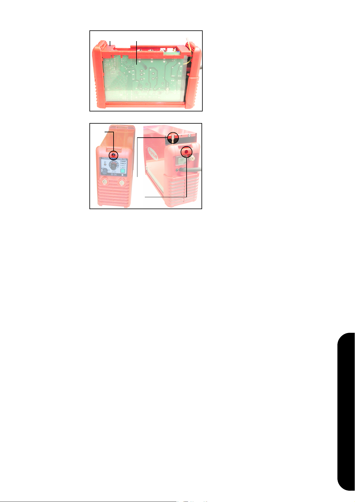
Gehäuse öffnen
(34)
Abb.1
(21) (37)
- Tragegurt entfernen
- Schraube 5x25-TX20 (34) an der
Gehäusevorderseite lösen
- Schraube 5x25-TX20 (35) an der
Gehäuserückseite lösen
- Gehäusemantel vorsichtig anheben und
„Erdleiter Gehäuse“ (36) abstecken
(36)
(35)
- Gehäuseversteifung (21) entfernen
- Printisolation (37) entfernen
Abb.2
42,0410,0806 032001
1
Page 2

FPA15 ausbauen
Abb.3
(40) (41) (42)(5)
- Flachbandkabel (42) vom Print FPA15
(5) abstecken
- 2-poligen Molexstecker (40) am Print
LCA15 abstecken
- 10-poligen Molexstecker (41) am Print
LCA15 abstecken
- Abdeckkappe vom „Einstellregler
Schweißstrom“ (6) abnehmen
(6)
Abb.4
(66)
Abb.5
Hinweis! Beim Lösen der Befestigungsmutter für den „Einstellregler Schweißstrom“, Einstellregler (6) festhalten
- Befestigungsmutter des Einstellreglers
(6) mit Steckschlüssel (Schlüsselweite
7) lösen
- Einstellregler (6) abziehen
- Rundmutter (66) lösen und entfernen
- Am Kupferbügel (55), Schraube M5x12
- TX20 (68) lösen
Abb.6
Abb.7
(69)
(68)
(55)
- TP 1500 TIG: Sechskantmutter (69)
(Schlüsselweite 13) für Verschraubung
-Buchse lockern
- TP 1500 / 1500 RC: In der -Buchse,
Schraube M5x12 (TX20) (70) lockern
(70)
Abb.8
2
Page 3

FPA15 ausbauen
(Fortsetzung)
Abb.9
(5)
(7)
(55)
- Kupferbügel (55) zur Seite schwenken
Hinweis! Print FPA15 (5) zuerst vorsichtig
an den vorderen Fixierstiften lösen.
- Print FPA15 (5) vorsichtig abheben und
entnehmen
DEUTSCH
FPA15 einbauen
Hinweis! Vor dem Aufsetzen des Prints FPA15 (5) auf die Fixierstifte, folgendes beach-
ten:
- TP 1500 RC / 1500 TIG: Dichtung für Anschlußbuchse Fernbedienung (7) dünn mit
Gleitmittel benetzen (Abb.10)
- TP 1500 RC / 1500 TIG: leichten Druck auf die Dichtung für Anschlußbuchse Fernbedienung (7) ausüben, um deren Austritt beim Andrücken des Prints FPA15 zu verhindern
- Print FPA15 (5) zuerst am hinteren Fixierstift einrasten lassen
- Print FPA15 vorsichtig andrücken, bis
sämtliche Fixierstifte eingerastet sind
(7)
Abb.10
- Kupferbügel (55) in ursprüngliche
Position zurückschwenken
Abb.11
(69) (70)
Abb.12 Abb.13
(55)
- TP 1500 TIG: Sechskantmutter (69)
(Schlüsselweite 13) für Verschraubung
-Buchse festziehen
- TP 1500 / 1500 RC: In der -Buchse,
Schraube M5x12 (TX20) (70) mit 2 Nm
festschrauben
3
Page 4

FPA15 einbauen
(Fortsetzung)
- Leitung X3 (blau) (72) und AbleitKondensatoren (73) am Kupferbügel
(55) mittels Schraube 5x12 - TX20 (68)
befestigen
- Schraube 5x12 - TX20 (68) mit 2 Nm
festschrauben
(72)(55)(68) (73)
Abb.14
- Rundmutter (66) festschrauben
(66)
Abb.15
- Einstellregler (6) aufsetzen
(6)
Abb.16
Abb.17
Hinweis! Beim Festziehen der Befestigungsmutter für den „Einstellregler
Schweißstrom“, Einstellregler (6) festhalten
- Befestigungsmutter des Einstellreglers
(6) mit Steckschlüssel (Schlüsselweite
7) festziehen
Abdeckkappe auf den „Einstellregler
Schweißstrom“ (6) aufsetzen
(40) (41) (42)(5)
- 10-poligen Molexstecker (41) am Print
LCA15 anstecken
- 2-poligen Molexstecker (40) am Print
LCA15 anstecken
- Flachbandkabel (42) gemäß Abb.17
oberhalb des Kabelbaumes verlegen
- Flachbandkabel (42) am Print FPA15
(5) anstecken
4
Page 5

Gehäuse schließen
Abb.19
(21) (37)
- Printisolation (37) einsetzen
- Gehäuseversteifung (21) einsetzen
DEUTSCH
(34)
Abb.20
(36)
(35)
- „Erdleiter Gehäuse“ (36) positionsrichtig
am Gehäusemantel anstecken
- Gehäusemantel aufsetzen
- Schraube 5x25-TX20 (35) an der
Gehäuserückseite festschrauben
- Schraube 5x25-TX20 (34) an der
Gehäusevorderseite festschrauben
- Tragegurt montieren
5
Page 6

Installation instructions: FPA15 board
Safety
Scope of supply
Tools needed
Warning! This modification may only be performed by suitably trained and skilled
electricians! Before opening up the machine, shift the mains switch to the "0" position
and unplug the machine from the mains!
N.B.! Follow the safety rules given in the Operating Instructions, especially the section
headed "Safety inspection".
The assembly “FPA 15 board” comprises the following component:
Item Designation N° of items
(5) FPA15 board (TP 1500 RC / 1500 TIG: 4,070,783,Z) ........................................ 1
FPA15 board (TP 1500: 4,070,782,Z) ................................................................ 1
Designation Article n°
- Manual torque screwdriver,1 to 6 Nm ......................................................42,0411,0013
- Bit insert TX 20, for torque screwdriver....................................................42,0411,0014
Additional tools
needed
Opening the
housing
- Socket spanner holder with 1/4’’ external hexagonal-socket drive and 1/4’’ external
square-socket drive, to fit torque screwdriver
- Socket-spanner insert - width-across 7- with 1/4’’ internal square-socket drive
(34)
(36)
(35)
Fig.1
(21) (37)
- Take off the carrying strap
- Undo the 5x25-TX20 screw (34) on the
front of the housing
- Undo the 5x25-TX20 screw (35) on the
rear of the housing
- Carefully lift the housing box and
disconnect the “housing earth
conductor” (36)
- Remove the housing stiffening element
(21)
- Remove the board insulator (37)
Fig.2
6
Page 7

Removing the
FPA15 board
Fig.3
(40) (41) (42)(5)
- Disconnect the ribbon cable (42) from
the FPA15 board (5)
- Unplug the 2-pole Molex plug (40) from
the LCA15 board
- Disconnect the 10-pole Molex plug (41)
from the LCA15 board
- Take off the cap from the “Weldingamperage setting dial“ (6)
(6)
Fig.4
(66)
Fig.5
N.B.! When undoing the fixing nut for the
“Welding-amperage setting dial“, hold the
dial (6) firmly
- Undo the fixing nut of the setting dial
(6) with the socket spanner (widthacross 7)
- Detach the setting dial (6)
- Undo and remove the round nut (66)
ENGLISH
- Undo the M5x12 - TX20 screw (68) on
the copper bracket (55)
Fig.6
Fig.7
(69)
(68)
(55)
- TP 1500 TIG: Loosen the hexagon nut
(69) (width-across=13) for the screwfixing of the socket
- TP 1500 / 1500 RC: In the socket,
loosen the M5x12 (TX20) screw (70)
(70)
Fig.8
7
Page 8

Removing the
FPA15 board
(continued)
Fig.9
(5)
(7)
(55)
- Swing the copper bracket (55) to one
side
N.B.! First carefully detach the FPA15
board (5) from the front alignment pins.
- Carefully lift the FPA15 board (5) and
remove it
Fitting the FPA15
board
N.B.! Before fixing the FPA15 board (5) on the alignment pins, do the following:
- TP 1500 RC / 1500 TIG: Apply a thin layer of lubricant to the seal of the remotecontrol socket (7) (Fig.10)
- TP 1500 RC / 1500 TIG: Apply gentle pressure to the seal of the remote-control
socket (7), to prevent it being forced out when you press on the FPA15 board
- Snap the FPA15 board (5) onto the rear alignment pin first
- Carefully press the FPA15 board until
all the alignment pins have snapped
into place
(7)
Fig.10
- Swing the copper bracket (55) back into
its original position
Fig.11
(69) (70)
Fig.12 Fig.13
(55)
- TP 1500 TIG: Tighten the hexagon nut
(69) (width-across=13) for the screwfixing of the socket
- TP 1500 / 1500 RC: In the socket,
tighten the M5x12 (TX20) screw (70)
8
Page 9

Fitting the FPA15
board
(continued)
- Fasten the X3 cable (blue) (72) and the
by-pass capacitors (73) onto the copper
bracket (55), using the 5x12 - TX20
screw (68)
- Tighten the 5x12 - TX20 screw (68)
with a torque of 2 Nm
(72)(55)(68) (73)
Fig.14
- Thigthen the round nut (66)
(66)
Fig.15
- Replace the setting dial (6)
(6)
Fig.16
Fig.17
N.B.! When thigthening the fixing nut for
the “Welding-amperage setting dial“, hold
the dial (6) firmly
- Thigthen the fixing nut of the setting
dial (6) with the socket spanner (widthacross 7)
ENGLISH
- Replace the cap to the “Weldingamperage setting dial“ (6)
(40) (41) (42)(5)
- Plug the 10-pole Molex plug (41) onto
board LCA15
- Plug the 2-pole Molex plug (40) onto
board LCA15
- Arrange the ribbon cable (42) above
the cable harness, as shown in Fig.17
- Plug the ribbon cable (42) to board
FPA15 (5)
9
Page 10

Closing the
housing
Fig.18
(21) (37)
- Insert the board insulator (37)
- Insert the housing stiffening element
(21)
(34)
Fig.19
(36)
(35)
- Plug the “housing earth conductor” (36)
onto the housing box, in the correct
position
- Replace the housing box
- Screw the 5x25-TX20 screw (35) back
onto the rear of the housing
- Screw the 5x25-TX20 screw (34) back
onto the front of the housing
- Fit the carrying strap back on again
10
Page 11

Instructions de montage de la carte FPA 15
Sécurité
Livraison
Outils
nécessaires
Attention ! Seuls les agents spécialisés et formés sont autorisés à effectuer ce monta-
ge ! Avant d’ouvrir l’appareil, mettre l’interrupteur principal sur „0“ et débrancher
l’appareil !
Remarque ! Conformez-vous aux consignes de sécurité contenues dans le mode
d’emploi, en particulier au chapitre „Inspection des systèmes de sécurité“.
Le sous-groupe „carte FPA 15“ (4,070,778,Z) comprend l’élément suivant :
Pos. Désignation Qté
(5) Carte FPA15 (TP 1500 RC / 1500 TIG : 4,070,783,Z) ....................................... 1
Carte FPA15 (TP 1500 : 4 070 782,Z) ............................................................... 1
Désignation N° d’article
- Tournevis dynamométrique manuel 1 à 6 Nm .........................................42,0411,0013
- Embout TX 20, adapté au tournevis dynamométrique.............................42,0411,0014
Outils supplémentaires nécessaires
Ouvrir le boîtier
- Adaptateur pour clé à douille avec entraînement 6 pans 1/4 ’’ et conducteur 4 pans
1/4 ’’ adapté au tournevis dynamométrique
- Douille - ouverture 7- avec entraînement 4 pans creux 1/4 ’’
(34)
(36)
(35)
Fig. 1
(21) (37)
- Enlever la courroie
- Dévisser la vis 5x25-TX20 (34) placée
sur l’avant du boîtier
- Dévisser la vis 5x25-TX20 (35) placée
sur l’arrière du boîtier
- Soulever l’enveloppe du boîtier avec
précaution et débrancher le „câble de
mise à la terre du boîtier“ (36)
- Enlever le renforcement du boîtier (21)
- Enlever la plaque isolante de la carte
(37)
Fig. 2
FRANÇAIS
11
Page 12

Démonter la
carte FPA15
Fig. 3
(40) (41) (42)(5)
- Débrancher le câble plat (42) de la
carte FPA15 (5)
- Débrancher le connecteur Molex 2
broches (40) de la carte LCA15
- Débrancher le connecteur Molex 10
broches (41) de la carte LCA15
- Retirer le capuchon du „régulateur du
courant de soudage“ (6)
(6)
Fig. 4
(66)
Fig. 5
Remarque ! Pour dévisser les écrous de
fixation du „régulateur de courant de
soudage“, bien tenir le régulateur (6)
- Dévisser l’écrou de fixation du régulateur (6) avec la clé à douille (ouverture
7)
- Sortir le régulateur (6)
- Dévisser et enlever l’écrou rond (66)
- Dévisser la vis M5x12 - TX20 (68) de
l’étrier en cuivre (55)
Fig. 6
Fig. 7
(69)
(68)
(55)
- TP 1500 TIG : Desserrer l’écrou hexagonal (69) (ouverture de clé 13) de la
vis du connecteur -
- TP 1500 / 1500 RC : Desserrer la vis
M5x12 (TX20) (70) du connecteur -
(70)
Fig. 8
12
Page 13

Démonter la
carte FPA15
(suite)
Fig. 9
(5)
(7)
(55)
- Faire pivoter l’étrier en cuivre (55) sur le
côté
Remarque ! Dévisser tout d’abord avec
précaution la carte FPA15 (5) des tiges de
fixation avant.
- Soulever et retirer avec précaution la
carte FPA15 (5)
Monter la carte
PFA15
Remarque ! Avant de placer la carte FPA15 (5) sur les tiges de fixation, respectez les
points suivants :
- TP 1500 RC / 1500 TIG : Humidifier légèrement le joint de la douille de la télécommande (7) avec du lubrifiant (fig. 10)
- TP 1500 RC / 1500 TIG : Exercer une légère pression sur le joint de la douille de la
télécommande (7) pour qu’il ne sorte pas lorsque vous appuyez sur la carte FPA15
- Engager tout d’abord la carte FPA15 (5) dans la tige de fixation arrière.
- Appuyer avec précaution sur la carte
FPA15 jusqu’à ce que toutes les tiges
de fixation soient engagées
(7)
Fig. 10
- Refaire pivoter l’étrier en cuivre (55)
dans sa position d’origine
Fig. 11
(69) (70)
Fig. 12 Fig. 13
13
(55)
- TP 1500 TIG : Visser l’écrou hexagonal
(69) (ouverture de clé 13) de la vis du
connecteur -
- TP 1500 / 1500 RC : Visser la vis
M5x12 - TX20 (70) dans le connecteur
- avec 2 Nm
FRANÇAIS
Page 14

Monter la carte
PFA15
(suite)
- Fixer la ligne X3 (bleue) (72) et les
condensateurs en dérivation (73) sur
l’étrier en cuivre (55) avec une vis 5x12
- TX20 (68)
- Visser la vis 5x12 - TX20 (68) avec 2
Nm
(72)(55)(68) (73)
Fig. 14
- Visser l’écrou rond (66)
(66)
Fig.15
- Monter le régulateur (6)
(6)
Fig.16
Fig. 17
Remarque ! Pour visser les écrous de
fixation du „régulateur de courant de
soudage“, bien tenir le régulateur (6)
- Visser l’écrou de fixation du régulateur
(6) avec la clé à douille (ouverture 7)
- Monter le capuchon du „régulateur sur
le courant de soudage“ (6)
(40) (41) (42)(5)
- Brancher le connecteur Molex 10
broches (41) sur la carte LCA15
- Brancher le connecteur Molex 2 broches (40) sur la carte LCA15
- Poser le câble plat (42) au-dessus du
faisceau de câbles conformément à la
fig. 17
- Brancher le câble plat (42) sur la carte
FPA15 (5)
14
Page 15
Fermer le boîtier
Fig. 18
(21) (37)
- Placer la plaque isolante de la carte
(37)
- Poser le renforcement du boîtier (21)
(34)
Fig. 19
(36)
(35)
- Brancher le „câble de mise à la terre du
boîtier“ (36) dans la bonne position sur
l’enveloppe du boîtier
- Monter l’enveloppe
- Visser la vis 5x25-TX20 (35) sur
l’arrière du boîtier
- Visser la vis 5x25-TX20 (34) sur l’avant
du boîtier
- Monter la courroie
15
FRANÇAIS
 Loading...