

Page 1

/ Battery Charging Systems / Welding Technology / Solar Electronics
EN-US
ES
FR
CBOX / CBOX 2 PC board - USA
Circuito impreso CBOX / CBOX 2 EE. UU.
Circuit imprimé CBOX / CBOX 2 USA
Installation instructions
Inverter for grid-connected photovoltaic systems
instrucciones de instalación
Inversores para instalaciones fotovoltaicas acopladas a la red
Instructions d'installation
Onduleur pour installations photovoltaïques connectées au réseau
42,0410,1877 004-06052013
Page 2

0
Page 3

Dear reader,
Introduction Thank you for the trust you have placed in our company and congratulations on buying this
high-quality Fronius product. These instructions will help you familiarize yourself with the
product. Reading the instructions carefully will enable you to learn about the many different
features it has to offer. This will allow you to make full use of its advantages.
Please also note the safety rules to ensure greater safety when using the product. Careful
handling of the product will repay you with years of safe and reliable operation. These are
essential prerequisites for excellent results.
EN-US
1
Page 4

2
Page 5

Contents
Safety rules ................................................................................................................................................ 5
Safety Rules Explanation...................................................................................................................... 5
General ................................................................................................................................................. 5
Utilization in Accordance with "Intended Purpose" ...............................................................................6
Environmental Conditions ..................................................................................................................... 6
Qualified Service Engineers.................................................................................................................. 6
Safety Measures at the Installation Location ........................................................................................ 6
EMC Device Classifications .................................................................................................................. 7
EMC Measures ..................................................................................................................................... 7
Electrical Installations ........................................................................................................................... 7
Protective Measures against ESD ........................................................................................................ 7
Safety Measures in Normal Operation.................................................................................................. 7
Safety Symbols ..................................................................................................................................... 8
Disposal ................................................................................................................................................ 8
Backup.................................................................................................................................................. 8
Copyright............................................................................................................................................... 8
General ...................................................................................................................................................... 9
Safety.................................................................................................................................................... 9
ESD Guidelines..................................................................................................................................... 9
Scope of Supply.................................................................................................................................... 10
Required tools....................................................................................................................................... 10
Replacing the CBOX/CBOX 2 PC board ................................................................................................... 11
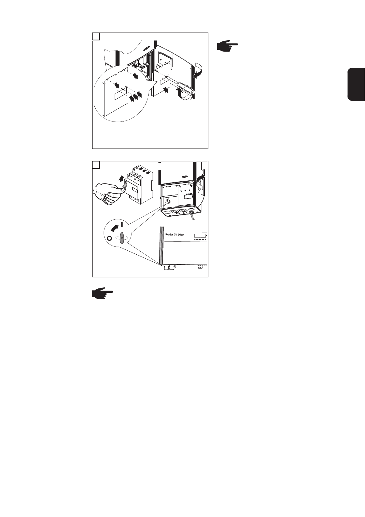
Preparation ........................................................................................................................................... 11
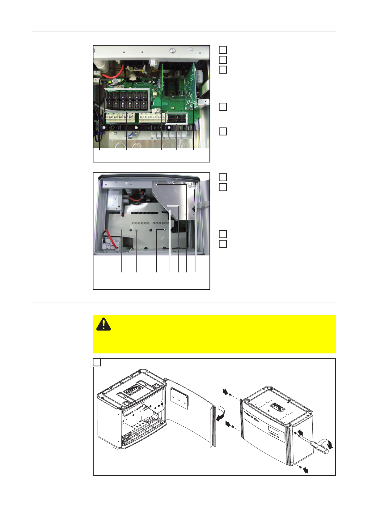
Removing Fuses and Plug-in Cards ..................................................................................................... 12
Replacing the CBOX/CBOX 2 PC board ..............................................................................................13
Inserting Fuses and Plug-in Cards........................................................................................................ 14
Finally.................................................................................................................................................... 14
Safety inspection........................................................................................................................................ 16
Responsibility........................................................................................................................................ 16
EN-US
3
Page 6

4
Page 7

Safety rules
EN-US
Safety Rules Explanation
General
DANGER! Indicates an imminently hazardous situation which, if not avoided, will
result in death or serious injury.
WARNING! Indicates a potentially hazardous situation which, if not avoided, will
result in death or serious injury.
CAUTION! Indicates a potentially harmful situation which, if not avoided, may result in minor and moderate injury or property damage.
NOTE! Indicates a risk of flawed results and possible damage to the equipment.
IMPORTANT! Indicates tips for correct operation and other particularly useful information.
It does not indicate a potentially damaging or dangerous situation.
If you see any of the symbols depicted in the "Safety rules," special care is required.
The device is manufactured using state-of-the-art technology and according
to recognized safety standards. If used incorrectly or misused, however, it can
cause
- injury or death to the operator or a third party,
- damage to the device and other material assets belonging to the operator,
- inefficient operation of the device
All persons involved in commissioning, maintaining and servicing the device
must
- be suitably qualified,
- have knowledge of and experience in dealing with electrical installations
and
- read and follow these operating instructions carefully
The operating instructions must always be at hand wherever the device is being used. In addition to the operating instructions, attention must also be paid
to any generally applicable and local regulations regarding accident prevention and environmental protection.
All safety and danger notices on the device
- must be kept in a legible state
- must not be damaged/marked
- must not be removed
- must not be covered, pasted or painted over
For the location of the safety and danger notices on the device, refer to the
section headed "General" in the operating instructions for the device.
Before switching on the device, remove any faults that could compromise
safety.
Your personal safety is at stake!
5
Page 8
Utilization in Accordance with
"Intended Purpose"
The device is to be used exclusively for its intended purpose.
Utilization for any other purpose, or in any other manner, shall be deemed to
be "not in accordance with the intended purpose." The manufacturer shall not
be liable for any damage resulting from such improper use.
Utilization in accordance with the "intended purpose" also includes
- carefully reading and obeying all the instructions and all the safety and
danger notices in the operating instructions
- performing all stipulated inspection and servicing work
- installation as specified in the operating instructions
The following guidelines should also be applied where relevant:
- Regulations of the utility regarding energy fed into the grid
- Instructions from the solar module manufacturer
Environmental
Conditions
Qualified Service
Engineers
Operation or storage of the device outside the stipulated area will be deemed
as "not in accordance with the intended purpose." The manufacturer is not responsible for any damages resulting from unintended use.
For exact information on permitted environmental conditions, please refer to
the "Technical data" in the operating instructions.
The servicing information contained in these operating instructions is intended
only for the use of qualified service engineers. An electric shock can be fatal.
Do not perform any actions other than those described in the documentation.
This also applies to those who may be qualified.
All cables and leads must be secured, undamaged, insulated and adequately
dimensioned. Loose connections, scorched, damaged or inadequately dimensioned cables and leads must be immediately repaired by authorized personnel.
Maintenance and repair work must only be carried out by authorized personnel.
It is impossible to guarantee that externally procured parts are designed and
manufactured to meet the demands made on them, or that they satisfy safety
requirements. Use only original replacement parts (also applies to standard
parts).
Do not carry out any modifications, alterations, etc. without the manufacturer's
consent.
Components that are not in perfect condition must be changed immediately.
Safety Measures
at the Installation
Location
6
When installing devices with openings for cooling air, ensure that the cooling air can enter
and exit unhindered through the vents. Only operate the device in accordance with the degree of protection shown on the rating plate.
Page 9

EMC Device Classifications
Devices in emission class A:
- Are only designed for use in industrial settings
- Can cause line-bound and radiated interference in other areas
Devices in emission class B:
- Satisfy the emissions criteria for residential and industrial areas.
This is also true for residential areas in which the energy is supplied from the public low-voltage grid.
EMC device classification as per the rating plate or technical data.
EN-US
EMC Measures
Electrical Installations
Protective Measures against
ESD
In certain cases, even though a device complies with the standard limit values
for emissions, it may affect the application area for which it was designed (e.g.,
when there is sensitive equipment at the same location, or if the site where the
device is installed is close to either radio or television receivers). If this is the
case, then the operator is obliged to take appropriate action to rectify the situation.
Electrical installations must only be carried out according to relevant national
and local standards and regulations.
Danger of damage to electrical components from electrical discharge. Suitable
measures should be taken to protect against ESD when replacing and installing components.
Safety Measures
in Normal Operation
Only operate the device when all protection devices are fully functional. If the
protection devices are not fully functional, there is a risk of
- injury or death to the operator or a third party,
- damage to the device and other material assets belonging to the operator,
- inefficient operation of the device
Any safety devices that are not functioning properly must be repaired by authorized personnel before the device is switched on.
Never bypass or disable protection devices.
7
Page 10
Safety Symbols
Devices marked with the UL test mark satisfy the requirements of the relevant
standards for the USA.
Devices marked with the CSA test mark satisfy the requirements of the relevant standards for Canada and the USA.
Disposal
Backup
Copyright
Do not dispose of this device with normal domestic waste! To comply with the
European Directive 2002/96/EC on Waste Electrical and Electronic Equipment and its implementation as national law, electrical equipment that has
reached the end of its life must be collected separately and returned to an approved recycling facility. Any device that you no longer require must be returned to your dealer, or you must locate the approved collection and recycling
facilities in your area. Ignoring this European Directive may have potentially
adverse affects on the environment and your health!
The user is responsible for backing up any changes made to the factory settings. The manufacturer accepts no liability for any deleted personal settings.
Copyright of these operating instructions remains with the manufacturer.
Text and illustrations are technically correct at the time of going to print. The
right to make modifications is reserved. The contents of the operating instructions shall not provide the basis for any claims whatsoever on the part of the
purchaser. If you have any suggestions for improvement, or can point out any
mistakes that you have found in the operating instructions, we will be most
grateful for your comments.
8
Page 11

General
EN-US
Safety
WARNING! An electric shock can be fatal. Danger from grid voltage and DC volt-
age from solar modules.
- The connection area should only be opened by a licensed electrician.
- The separate power stage set area should only be disconnected from the
connection area after first being disconnected from the grid power.
- The separate power stage set area should only be opened by Fronius-trained
service technicians.
- Never work with live wires! Before any connection work, make sure that the
inverter's AC and DC wires are not charged.
- In the USA, all electrical installations must be in accordance with the National
Electrical Code, ANSI/NFPA 70, and any other codes and regulations applicable to the installation site.
- Installations in Canada must comply with the applicable Canadian standards.
Never work with live wires! Before any connection work, make sure that the inverter's AC and DC wires are not charged.
WARNING! An electric shock can be fatal. Danger from residual voltage from capacitors.
You must wait until the capacitors have discharged. Discharge takes 5 minutes.
Use a suitable measuring tool to ensure that the capacitors are discharged.
WARNING! Incorrect operation and work performed incorrectly can cause serious injury and damage! Only qualified staff are authorized to install your inverter
and only within the scope of the respective technical regulations. It is essential
that you read the "Safety regulations" chapter before commissioning the equipment or carrying out service or maintenance work.
ESD Guidelines
NOTE! Requirements for electrical installations may be subject to national stan-
dards and regulations, and these must be followed accordingly.
NOTE! Observe ESD guidelines when handling electronic components and PC
boards. This primarily applies to ESD-compatible
- Packaging
- Work surfaces
-Floors
-Seating
- Grounding options
- Handling
No guarantee or warranty claims can be made in respect of any improperly handled electronic component or PC board.
9
Page 12

Scope of Supply The scope of supply includes:
- CBOX 2 PC board
Required tools - TX 20 Torx screwdriver
- TX 25 Torx screwdriver
- Hand torque wrench with TX 20/25 bit insert
10
Page 13
Replacing the CBOX/CBOX 2 PC board
1
4
2
3
Fronius IG Plus V
a)
b)
5
EN-US
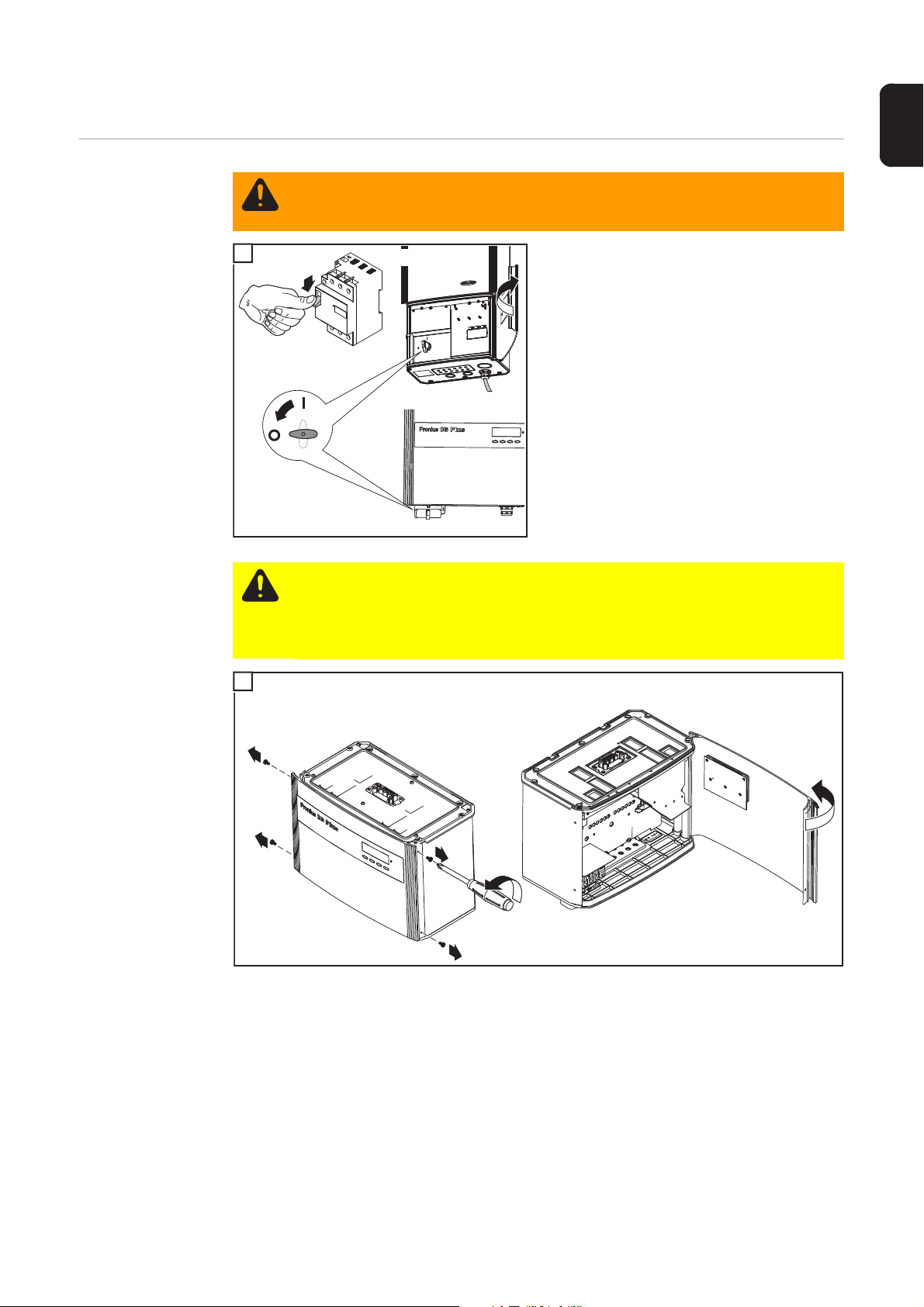
Preparation
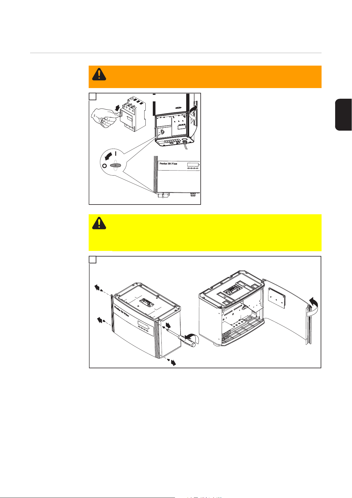
WARNING! An electric shock can be fatal. Danger from grid voltage and DC volt-
age from solar modules. Never work with live wires! Make sure that the AC and
DC wires are not charged before you start work on the inverter.
1
AC
1
o
n
o
ff
Fronius IG Plus
If present, switch off the external AC and
DC disconnect and lock it off to avoid inad-
2
vertent operation.
OFF
2
3
Fronius IG Plus V
CAUTION! An inadequate grounding conductor connection can cause serious injuries to persons and damage to (or loss of) property. The housing screws provide
an adequate grounding conductor connection for the housing ground and should
not be replaced under any circumstances by other screws that do not provide a
proper grounding conductor connection.
2
11
Page 14
2
3
Fronius IG Plus
NOTE! Remove all fixing screws
from any available option cards
1
3
2
7
4
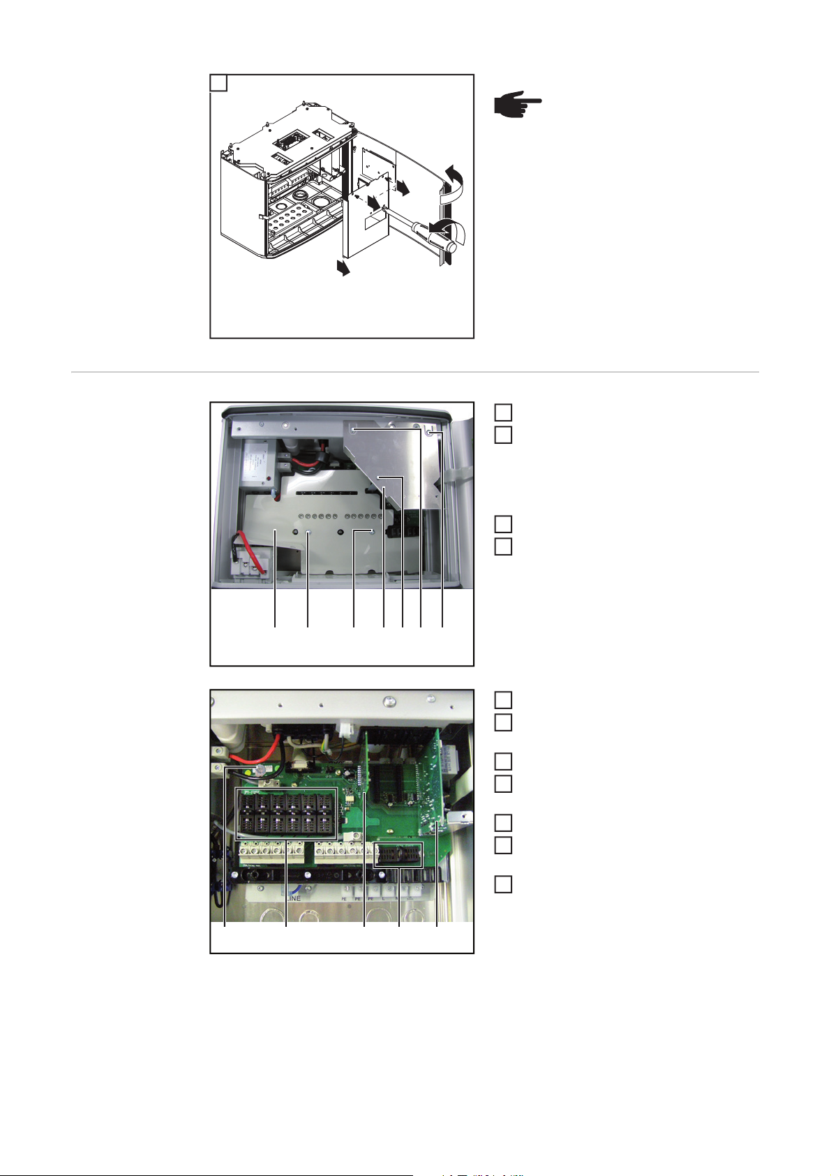
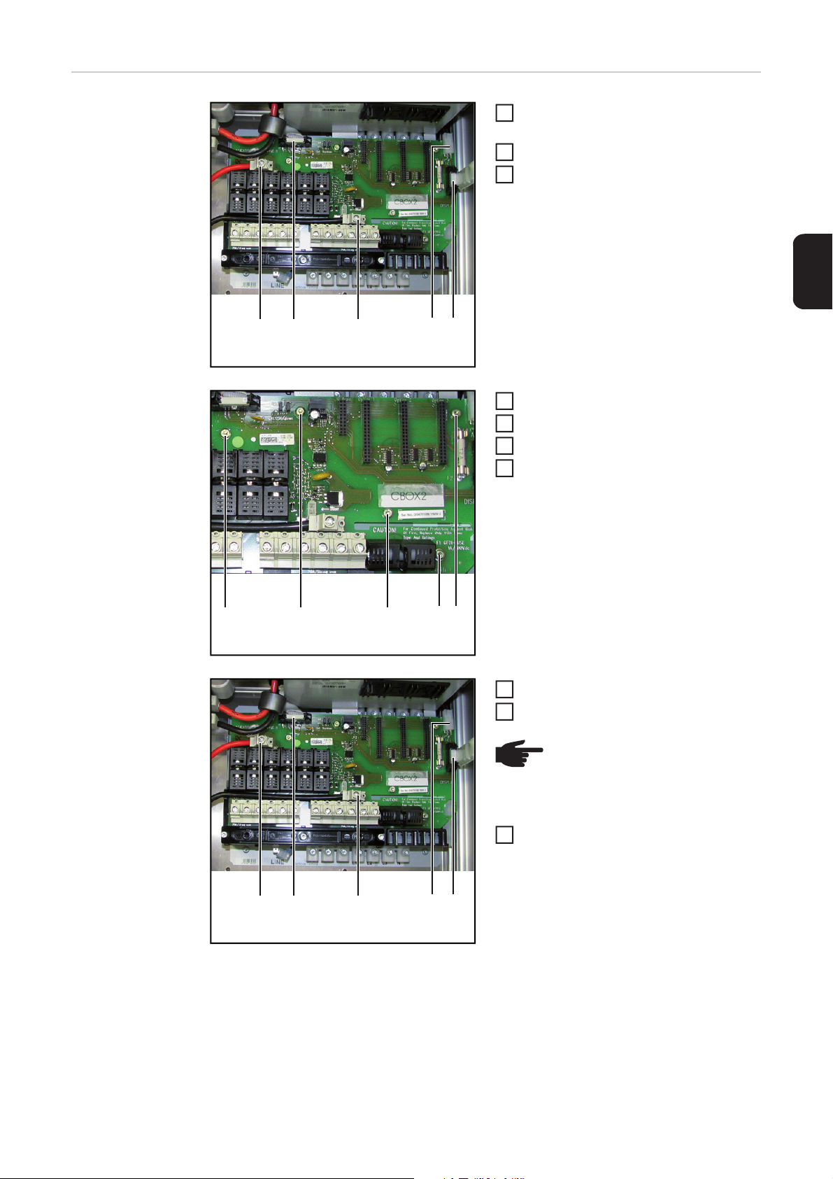
Removing Fuses
and Plug-in Cards
(1) (2) (3) (4) (5) (6) (7)
(9)(8) (10) (11) (12)
Remove screws (2) and (3)
1
Remove insulating cover (1)
2
Perform steps 3 and 4 only for FRONIUS IG
Plus V:
Remove screws (5) and (7)
Remove plate cover (4)
4
Remove jumper (8)
5
Remove GFDI fuse (11) for the solar
6
module grounding
Remove string fuses or bolts (9)
7
Disconnect DC wires (at the module
8
side)
Disconnect the IG Brain PC board (10)
9
If present, disconnect other plug-in
10
cards (12)
If the NL-MON plug-in card is present,
11
11
first disconnect the Molex plug from the
NL- MON PC board.
12
Page 15

Replacing the
(1) (2)
(3)
(4) (5)
2
10
CBOX/CBOX 2 PC
board
Disconnect 2 DC main switch- cables
1
l (1, 3)
Disconnect 2 ribbon cables (2, 5)
Disconnect 4-pin plug (4)
3
Remove the screws (6)
4
Remove the CBOX PC board
5
Insert new PC board
6
Tighten the screws (6) to 3 Nm /
7
2.2 ft lb.
EN-US
(6) (6) (6) (6) (6)
(1) (2)
(3)
(4) (5)
Connect 4-pin plug (4)
8
Connect 2 ribbon cables (2, 5)
9
NOTE! When connecting the DC
main switch cables, ensure that
the polarity is correct. (cable label)
Connect 2 DC main switch cables (1,
3)
tightening torque: 2 Nm / 1.5 ft lb.
13
Page 16
Inserting Fuses
(9)(8) (10) (11) (12)
2
4
4
3
5
2
Fronius IG Plus V
1
and Plug-in Cards
Connect jumper (8)
1
Insert IG Brain PC board (10)
If present, insert other plug-in cards
3
(12)
– If the NL-MON plug-in card is pre-
sent, first connect the Molex plug.
Connect DC cable according to the inverter operating instructions and insert
fuses (9)
Insert GFDI fuse (11) (max. 1 A ac-
5
cording to the inverter instruction manual)
Insert insulating cover (1)
6
Secure screws (2) and (3)
7
tightening torque: 2 Nm / 1.5 ft lb.
Perform steps 8 and 9 only for FRONIUS IG
Plus V:
Finally...
Insert plate cover (4)
8
Fasten screws (5) and (7)
9
tightening torque: 2 Nm / 1.5 ft lb.
(1) (2) (3) (4) (5) (6) (7)
CAUTION! An inadequate grounding conductor connection can cause serious injuries to persons and damage to (or loss of) property. The housing screws provide
an adequate grounding conductor connection for the housing ground and should
not be replaced under any circumstances by other screws that do not provide a
proper grounding conductor connection.
1
14
Page 17

7
1
6
5
4
3
2
1
NOTE! Attach all fixing screws
from any available option cards.
EN-US
Fronius IG Plus
2
ON
2
Fronius IG Plus V
NOTE! The IG Brain PC board and the IG Disp PC board must always have the
same firmware version. It is therefore necessary to update the inverter firmware
after replacing the IG Brain PC board or the IG Disp PC board.
The software and operating instructions for Fronius Solar.update can be found at
http://www.fronius.com in the Fronius Download Center.
Fronius IG Plus
1
on
off
If available, turn on the external AC and DC
disconnect.
2
AC
15
Page 18

Safety inspection
Responsibility The repair technician is responsible for carrying out and documenting the inspection cor-
rectly and for making a correct decision.
Please refer to the enclosed document "Safety inspection Fronius IG Plus - IG Plus V" for
information regarding the scope and implementation of the safety inspection.
16
Page 19

Estimado lector
Introducción Le agradecemos su confianza y queremos felicitarle por la adquisición de este producto
de Fronius de alta calidad técnica. El presente manual le ayudará a familiarizarse con el
producto. Una lectura detenida del manual le permitirá conocer las múltiples posibilidades
de su producto de Fronius. Solo así podrá aprovechar todas sus ventajas.
Observe también las indicaciones de seguridad para conseguir una mayor seguridad en
el lugar en el que emplee el producto. Un manejo cuidadoso de su producto ayuda a conseguir una calidad y fiabilidad duraderas. Todo ello constituye la condición previa esencial
para lograr unos resultados excelentes.
ES
17
Page 20

18
Page 21

Tabla de contenido
Normativa de seguridad............................................................................................................................. 21
Explicación de las indicaciones de seguridad....................................................................................... 21
Generalidades....................................................................................................................................... 21
Utilización prevista................................................................................................................................ 22
Condiciones ambientales...................................................................................................................... 22
Personal cualificado.............................................................................................................................. 22
Medidas de seguridad en el lugar de empleo ....................................................................................... 22
Clasificaciones de equipos CEM .......................................................................................................... 23
Medidas de compatibilidad electromagnética (CEM)............................................................................ 23
Instalaciones eléctricas......................................................................................................................... 23
Medidas de protección ESD ................................................................................................................. 23
Medidas de seguridad en servicio normal ............................................................................................ 23
Identificación de seguridad ................................................................................................................... 24
Eliminación............................................................................................................................................ 24
Protección de datos .............................................................................................................................. 24
Derechos de autor ................................................................................................................................ 24
Generalidades............................................................................................................................................ 25
Seguridad.............................................................................................................................................. 25
Disposiciones ESD ............................................................................................................................... 25
Volumen de suministro ......................................................................................................................... 26
Herramientas necesarias...................................................................................................................... 26
Cambiar el circuito impreso CBOX / CBOX 2 ............................................................................................ 27
Preparación........................................................................................................................................... 27
Retirar los fusibles y las tarjetas enchufables....................................................................................... 28
Cambiar el circuito impreso CBOX / CBOX2 ........................................................................................29
Introducir los fusibles y las tarjetas enchufables................................................................................... 30
Actividades finales ................................................................................................................................ 30
Comprobación relacionada con la técnica de seguridad ........................................................................... 32
Responsabilidad ................................................................................................................................... 32
ES
19
Page 22

20
Page 23

Normativa de seguridad
Explicación de
las indicaciones
de seguridad
Generalidades
¡PELIGRO! Indica un peligro inminente. Si no se evita este peligro, las conse-
cuencias son la muerte o lesiones de carácter muy grave.
ES
¡ADVERTENCIA! Indica una situación posiblemente peligrosa. Si no se evita
esta situación, las consecuencias pueden ser la muerte y lesiones de carácter
muy grave.
¡PRECAUCIÓN! Indica una situación posiblemente perjudicial. Si no se evita
esta situación, se pueden producir lesiones de carácter leve o insignificantes, así
como daños materiales.
¡OBSERVACIÓN! Designa el peligro de obtener unos resultados mermados de
trabajo y de que se puedan producir daños en el equipamiento.
¡IMPORTANTE! Indica consejos de aplicación y otras informaciones especialmente útiles.
No es una palabra señaladora que indique una situación perjudicial o peligrosa.
Cuando vea uno de los símbolos representados en el capítulo "Indicaciones de seguridad", se requiere un mayor grado de atención.
El aparato ha sido fabricado según el estado de la técnica y las reglas reconocidas relacionadas con la técnica de seguridad. A pesar de ello, cualquier
manejo incorrecto o uso inadecuado implica un peligro para:
- La integridad física y la vida del operario o de terceras personas.
- El aparato y otros valores materiales del empresario.
- El trabajo eficiente con el aparato.
Todas las personas relacionadas con la puesta en servicio, el mantenimiento
y la conservación del aparato deben:
- Poseer la cualificación correspondiente.
- Poseer conocimientos en el manejo de instalaciones eléctricas.
- Leer completamente y seguir escrupulosamente este manual de instrucciones.
El manual de instrucciones se debe guardar constantemente en el lugar de
empleo del aparato. De forma complementaria al manual de instrucciones se
deben tener en cuenta las reglas válidas a modo general, así como las reglas
locales respecto a la prevención de accidentes y la protección medioambiental.
Todas las indicaciones de seguridad y peligro en el aparato:
- Se deben mantener en estado legible.
- No se deben dañar.
- No se deben retirar.
- No se deben tapar ni cubrir con pegamento o pintura.
Las posiciones de las indicaciones de seguridad y peligro en el aparato figuran en el capítulo "Generalidades" del manual de instrucciones de su aparato.
Cualquier error que pueda mermar la seguridad debe ser eliminado antes de
conectar el aparato.
¡Se trata de su seguridad!
21
Page 24

Utilización prevista
Se debe utilizar el aparato exclusivamente para el empleo en el sentido de la
utilización prevista.
Cualquier otro uso se considera como no previsto por el diseño constructivo.
El fabricante reclina cualquier responsabilidad frente a los daños que se pudieran originar.
También forman parte de la utilización prevista:
- La lectura completa y la observación de todas las indicaciones, así como
de todas las indicaciones de seguridad y peligro del manual de instrucciones.
- La observación de todos los trabajos de inspección y mantenimiento.
- El montaje según el manual de instrucciones.
En caso de darse el caso, deben aplicarse también las siguientes directivas:
- Disposiciones de la empresa suministradora de energía para la alimentación de la red.
- Indicaciones de los fabricante de los módulos solares.
Condiciones ambientales
Personal cualificado
Cualquier servicio o almacenamiento del equipo fuera del campo indicado será considerado como no previsto. El fabricante declina cualquier responsabilidad frente a los daños que se pudieran originar.
En los datos técnicos del manual de instrucciones figura información detallada
acerca de las condiciones ambientales admisibles.
La información de servicio en este manual de instrucciones está destinada exclusivamente a personal técnico cualificado. Una descarga eléctrica puede
ser mortal. No realizar actividades diferentes a las que se indican en la documentación. Lo mismo es aplicable cuando el personal está cualificado a tal fin.
Todos los cables y líneas deben estar fijados, intactos, aislados y tener una
dimensión suficiente. Las uniones sueltas, cables y líneas chamuscadas, dañadas o con una dimensión insuficiente deben ser reparadas inmediatamente
por un taller especializado autorizado.
El mantenimiento y la reparación deben ser efectuados sólo por un taller especializado autorizado.
En caso de piezas procedentes de otros fabricantes no queda garantizado
que hayan sido diseñadas y fabricadas de acuerdo con los esfuerzos y la seguridad. Utilizar sólo piezas de recambio originales (lo mismo es aplicable a
piezas normalizadas).
No se deben efectuar cambios, montajes o transformaciones en el aparato sin
previa autorización del fabricante.
Se deben sustituir inmediatamente los componentes que no se encuentren en
perfecto estado.
Medidas de seguridad en el lugar
de empleo
22
Durante la instalación de aparatos con aperturas de aire de refrigeración debe asegurarse
que el aire de refrigeración pueda entrar y salir libremente por las ranuras de ventilación.
Utilizar el aparato sólo según el tipo de protección indicado en la placa de características.
Page 25

Clasificaciones
de equipos CEM
Equipos de la clase de emisión A:
- Solo están destinados al uso en zonas industriales.
- Pueden provocar perturbaciones condicionadas a la línea e
irradiadas en otras regiones.
Equipos de la clase de emisión B:
- Cumplen los requisitos de emisión en zonas residenciales e industriales. Lo mismo es aplicable a zonas residenciales en las
que la energía se suministra desde una red de baja tensión pública.
Clasificación de equipos CEM según la placa de características o
los datos técnicos.
ES
Medidas de compatibilidad electromagnética
(CEM)
Instalaciones
eléctricas
Medidas de protección ESD
En casos especiales puede ocurrir que, a pesar de cumplir valores límite de
emisión normalizados, se produzcan influencias para el campo de aplicaciones previsto (por ejemplo, cuando hay aparatos sensibles en el lugar de emplazamiento o cuando el lugar de emplazamiento se encuentra cerca de
receptores de radio o televisión). En este caso, el empresario está obligado a
tomar unas medidas adecuadas para eliminar las perturbaciones.
Realizar las instalaciones eléctricas sólo según las correspondientes normas
y disposiciones nacionales y regionales.
Riesgo de daños de los componentes electrónicos debido a una descarga
eléctrica. En caso de sustitución e instalación de los componentes deben tomarse unas medidas de protección ESD adecuadas.
Medidas de seguridad en servicio
normal
Sólo se deberá utilizar el aparato cuando todos los dispositivos de seguridad
tengan plena capacidad de funcionamiento. Si los dispositivos de seguridad
no disponen de su plena capacidad de funcionamiento existe peligro para:
- La integridad física y la vida del operario o de terceras personas.
- El aparato y otros valores materiales del empresario.
- El trabajo eficiente con el aparato.
Antes de la conexión del aparato se debe encomendar a un taller especializado autorizado la reparación de los dispositivos de seguridad que no dispongan de su plena capacidad de funcionamiento.
Los dispositivos de seguridad jamás se deben anular o poner fuera de servicio.
23
Page 26

Identificación de
seguridad
Los equipos identificados con la certificación UL cumplen las disposiciones de
las normas relevantes para Canadá y EE. UU.
Los equipos identificados con la certificación CSA cumplen las disposiciones
de las normas relevantes para Canadá y EE. UU.
Eliminación
Protección de datos
Derechos de autor
¡No tire este aparato junto con el resto de las basuras domésticas! De conformidad con la Directiva europea 2002/96/CE sobre residuos de aparatos eléctricos y electrónicos y su transposición al derecho nacional, los aparatos
eléctricos usados deben ser recogidos por separado y reciclados respetando
el medio ambiente. Asegúrese de devolver el aparato usado al distribuidor o
solicite información sobre los sistemas de desecho y recogida locales autorizados. ¡Hacer caso omiso a esta directiva de la UE puede acarrear posibles
efectos sobre el medio ambiente y su salud!
El usuario es responsable de la salvaguardia de datos de las modificaciones
frente a los ajustes de fábrica. El fabricante no es responsable en caso de que
se borren los ajustes personales.
Los derechos de autor respecto al presente manual de instrucciones son propiedad del fabricante.
El texto y las ilustraciones corresponden al estado de la técnica en el momento de la impresión. Reservado el derecho a modificaciones. El contenido del
manual de instrucciones no justifica ningún tipo de derecho por parte del comprador. Agradecemos cualquier propuesta de mejora e indicaciones respecto
a errores en el manual de instrucciones.
24
Page 27

Generalidades
Seguridad
¡ADVERTENCIA! Las descargas eléctricas pueden ser mortales. Peligro origina-
do por la tensión de red y la tensión DC de los módulos solares.
- Solo instaladores eléctricos oficiales deben abrir la zona de conexión.
- La zona separada de las etapas de potencia solo se puede separar de la
zona de conexión cuando no tiene tensión.
- Solo personal de servicio formado por Fronius debe abrir la zona separada
de las etapas de potencia.
- Antes de realizar cualquier tipo de trabajo de conexión se debe procurar que
los lados AC y DC delante del inversor no tengan tensión.
- En EE. UU. deben realizarse todas las conexiones eléctricas según el National Electrical Code ANSI/NFPA 70 y las demás directivas vigentes en el lugar de instalación.
- Las instalaciones en Canadá deben realizarse según las normas canadienses vigentes.
Antes de realizar cualquier tipo de trabajo de conexión se debe procurar que los
lados AC y DC delante del inversor no tengan tensión.
¡ADVERTENCIA! Las descargas eléctricas pueden ser mortales. Peligro originado por la tensión residual de los condensadores.
Esperar hasta que se descarguen los condensadores. El tiempo de descarga es
de 5 minutos.
Con la ayuda de un medidor adecuado, asegurarse de que los condensadores
están descargados.
ES
Disposiciones
ESD
¡ADVERTENCIA! El manejo incorrecto y los trabajos realizados de forma defec-
tuosa pueden causar graves daños personales y materiales. La puesta en servicio del inversor solo debe ser efectuada por personal formado y en el marco de
las disposiciones técnicas. Antes de la puesta en servicio y de la realización de
trabajos de servicio y reparación, resulta imprescindible leer el capítulo "Disposiciones de seguridad".
¡OBSERVACIÓN! Los requisitos para instalaciones eléctricas pueden estar sujetos a normas y disposiciones nacionales y deben ser cumplidos según las mismas.
¡OBSERVACIÓN! Observar las disposiciones ESD para manipular los circuitos
impresos y componentes electrónicos. Estas incluyen sobre todo elementos que
cumplen las disposiciones ESD como
- Embalajes
- Superficies de trabajo
-Suelos
- Asientos
- Posibilidades de puesta a tierra
- Manipulación
No se pueden reclamar derechos de garantía por un componente electrónico o un circuito
impreso que no haya sido tratado debidamente.
25
Page 28

Volumen de suministro
El volumen de suministro incluye lo siguiente:
- Circuito impreso CBOX 2
Herramientas necesarias
- Destornillador Torx TX 20
- Destornillador Torx TX 25
- Atornillador de par manual con inserto bit TX 20 / 25
26
Page 29

Cambiar el circuito impreso CBOX / CBOX 2
1
4
2
3
Fronius IG Plus V
a)
b)
5
Preparación
¡ADVERTENCIA! Las descargas eléctricas pueden ser mortales. Peligro origina-
do por la tensión de red y la tensión DC de los módulos solares. Antes de realizar
cualquier tipo de trabajo en el inversor se debe procurar que los lados AC y DC
no tengan tensión.
1
OFF
2
Fronius IG Plus V
¡PRECAUCIÓN! Una conexión inapropiada del conductor de protección puede
causar graves daños personales y materiales. Los tornillos de la caja del aparato
constituyen una conexión adecuada del conductor de protección para la puesta
a tierra de la caja y nunca deben ser sustituidos por otros tornillos sin una conducción del conductor de protección fiable.
AC
1
3
ES
Fronius IG Plus
o
n
o
ff
Si estuviera disponible, desconectar el seccionador AC y DC externo y asegurarlo
2
contra cualquier reconexión accidental.
2
27
Page 30

2
3
Fronius IG Plus
¡OBSERVACIÓN! Retirar todos
los tornillos de fijación de las tarjetas opcionales que pudieran estar
disponibles.
1
3
2
7
4
Retirar los fusibles y las tarjetas
enchufables.
(1) (2) (3) (4) (5) (6) (7)
(9)(8) (10) (11) (12)
Soltar los tornillos (2) - (3).
1
Retirar la cubierta de aislamiento (1).
2
Realizar los pasos de 3 a 4 solo en el Fronius IG Plus V:
Soltar los tornillos (5) - (7).
Retirar la cubierta de chapa (4).
4
Retirar el saltador (8).
5
Retirar el fusible GFDI (11) para la pu-
6
esta a tierra del módulo solar.
Retirar los fusibles de serie fotovoltai-
7
ca o los pernos (9).
Cerrar el cable DC (lado de módulo).
8
Desenchufar el circuito impreso de la
9
tarjeta IG Brain (10).
Si estuvieran disponibles, desenchufar
10
las demás tarjetas enchufables (12).
Si estuviera disponible, antes de retirar
11
11
la tarjeta enchufable NL-MON, extraer
la clavija Molex del circuito impreso
NL-MON.
28
Page 31

Cambiar el circui-
(1) (2)
(3)
(4) (5)
2
10
to impreso CBOX
/ CBOX2
Cerrar los 2 interruptores principales
1
DC -para los cables (1, 3).
Desenchufar los 2 cables de cinta pla-
na (2, 5).
Desenchufar la clavija de 4 polos (4).
3
Soltar los tornillos (6).
4
Extraer el circuito impreso CBOX.
5
Colocar el circuito impreso nuevo
6
Enroscar los tornillos (6) con 3 Nm /
7
2.2 ft lb.
ES
(6) (6) (6) (6) (6)
(1) (2)
(3)
(4) (5)
Conectar la clavija de 4 polos (4).
8
Enchufar los 2 cables de cinta plana
9
(2, 5).
¡OBSERVACIÓN! ¡Al conectar
los cables del interruptor principal
DC debe prestarse atención a la
polaridad correcta! (Rotulación de
cable)
Conectar los 2 cables del interruptor
principal DC (1, 3).
Par de apriete: 2 Nm / 1.5 ft lb.
29
Page 32

Introducir los fu-
(9)(8) (10) (11) (12)
2
4
8
4
3
5
2
Fronius IG Plus V
1
sibles y las tarjetas enchufables.
Enchufar el saltador (8).
1
Enchufar el circuito impreso de la tarjeta IG-Brain (10).
Si estuvieran disponibles, enchufar las
3
demás tarjetas enchufables (12).
– Si estuviera disponible, antes de
introducir la tarjeta enchufable NLMON, enchufar la clavija Molex.
Conectar los cables DC según el manual de instrucciones del inversor y colocar los fusibles (9).
Colocar el fusible GFDI (11)
5
(máx. 1 amperios según el manual de
instrucciones del inversor).
Colocar la cubierta de aislamiento (1).
6
Fijar los tornillos (2) - (3).
7
Par de apriete: 2 Nm / 1.5 ft lb.
Realizar los pasos de 8 a 9 solo en el Fronius IG Plus V:
Actividades finales
Colocar la cubierta de chapa (4).
Fijar los tornillos (5) - (7).
9
Par de apriete: 2 Nm / 1.5 ft lb.
(1) (2) (3) (4) (5) (6) (7)
¡PRECAUCIÓN! Una conexión inapropiada del conductor de protección puede
causar graves daños personales y materiales. Los tornillos de la caja del aparato
constituyen una conexión adecuada del conductor de protección para la puesta
a tierra de la caja y nunca deben ser sustituidos por otros tornillos sin una conducción del conductor de protección fiable.
1
30
Page 33
7
1
6
5
4
3
2
1
¡OBSERVACIÓN! Montar todos
los tornillos de fijación de las tarjetas opcionales que pudieran estar
disponibles.
ES
Fronius IG Plus
2
ON
2
Fronius IG Plus V
¡OBSERVACIÓN! El circuito impreso IG-Brain o el circuito impreso IG-Disp deben tener siempre la misma versión de firmware. Por lo tanto, es necesario actualizar el firmware del inversor después de la sustitución del circuito impreso IGBrain o del circuito impreso IG-Disp.
El software y el manual de instrucciones para Fronius Solar.update se encuentran disponibles en el Fronius Download Center en http://www.fronius.com.
Fronius IG Plus
1
on
off
Conectar el seccionador AC y DC externo
si estuviera disponible.
2
AC
31
Page 34

Comprobación relacionada con la técnica de seguridad
Responsabilidad El técnico de reparación es responsable de realizar la comprobación y de documentarla,
así como de decidir qué comprobación es la adecuada.
El alcance y la realización de la comprobación relacionada con la técnica de seguridad deben determinarse según el documento "Comprobación relacionada con la técnica de seguridad Fronius IG Plus - IG Plus V" adjunto.
32
Page 35

Cher lecteur
Introduction Nous vous remercions de la confiance que vous nous témoignez et nous vous félicitons
d'avoir acquis ce produit Fronius de haute qualité technique. Les présentes Instructions de
service doivent vous permettre de vous familiariser avec ce produit. Par une lecture attentive, vous apprendrez à connaître les diverses possibilités de votre produit Fronius. C'est
ainsi seulement que vous pourrez en exploiter au mieux tous les avantages.
Respectez les consignes de sécurité et veillez par ce biais à garantir davantage de sécurité sur le lieu d'utilisation du produit. Une manipulation appropriée de ce produit garantit
sa qualité et sa fiabilité à long terme. Ces deux critères sont des conditions essentielles
pour un résultat optimal.
FR
33
Page 36

34
Page 37

Sommaire
Consignes de sécurité ............................................................................................................................... 37
Explication des consignes de sécurité.................................................................................................. 37
Généralités............................................................................................................................................ 37
Utilisation conforme à la destination ..................................................................................................... 38
Conditions ambiantes ........................................................................................................................... 38
Personnel qualifié ................................................................................................................................. 38
Mesures de sécurité sur le site d'exploitation ....................................................................................... 38
Classification CEM des appareils ......................................................................................................... 39
Mesures relatives à la CEM .................................................................................................................. 39
Installations électriques......................................................................................................................... 39
Mesures de sécurité contre les décharges électrostatiques ................................................................. 39
Mesures de sécurité en mode de fonctionnement normal .................................................................... 39
Marquage de sécurité ........................................................................................................................... 40
Élimination ............................................................................................................................................ 40
Sûreté des données.............................................................................................................................. 40
Droits d'auteur....................................................................................................................................... 40
Généralités................................................................................................................................................. 41
Sécurité................................................................................................................................................. 41
Directives relatives aux décharges électrostatiques .............................................................................41
Livraison................................................................................................................................................ 42
Outils requis.......................................................................................................................................... 42
Remplacer le circuit imprimé CBOX / CBOX 2 .......................................................................................... 43
Préparation ........................................................................................................................................... 43
Retirer les fusibles et les cartes enfichables......................................................................................... 44
Remplacer le circuit imprimé CBOX / CBOX2 ...................................................................................... 45
Mettre en place les fusibles et les cartes enfichables........................................................................... 46
Opérations finales................................................................................................................................. 46
Contrôle technique de sécurité .................................................................................................................. 48
Responsabilité ...................................................................................................................................... 48
FR
35
Page 38

36
Page 39

Consignes de sécurité
Explication des
consignes de sécurité
Généralités
DANGER ! Signale un risque de danger immédiat. S'il n'est pas évité, il peut en-
traîner la mort ou des blessures graves.
AVERTISSEMENT ! Signale une situation potentiellement dangereuse. Si elle
n'est pas évitée, elle peut entraîner la mort ou des blessures graves.
ATTENTION ! Signale une situation susceptible de provoquer des dommages. Si
elle n'est pas évitée, elle peut entraîner des blessures légères ou minimes, ainsi
que des dommages matériels.
REMARQUE! Désigne un risque de mauvais résultats de travail et de possibles
dommages sur l'équipement.
IMPORTANT! Désigne des astuces d'utilisation et d'autres informations particulièrement
utiles. Cette mention ne signale pas une situation dangereuse ou susceptible de provoquer
des dommages.
Soyez extrêmement attentif lorsque vous voyez l'un des symboles illustrés dans le chapitre
« Consignes de sécurité ».
Cet appareil est fabriqué selon l'état actuel de la technique et conformément
aux règles techniques de sécurité en vigueur. Cependant, en cas d'erreur de
manipulation ou de mauvaise utilisation, il existe un risque
- de blessure et de mort pour l'utilisateur ou des tiers,
- de dommages pour l'appareil et les autres biens de l'utilisateur,
- d'inefficacité du travail avec l'appareil.
Toutes les personnes concernées par la mise en service, l'utilisation et la
maintenance de l'appareil doivent
- posséder les qualifications correspondantes,
- connaître le maniement des installations électriques et
- lire attentivement et suivre avec précision les présentes Instructions de
service.
Les Instructions de service doivent être conservées en permanence sur le lieu
d'utilisation de l'appareil. En complément des présentes Instructions de service, les règles générales et locales en vigueur concernant la prévention des accidents et la protection de l'environnement doivent être respectées.
Concernant les avertissements de sécurité et de danger présents sur l'appareil
- veiller à leur lisibilité permanente
- ne pas les détériorer
- ne pas les retirer
- ne pas les recouvrir, ni coller d'autres autocollants par-dessus, ni les peindre.
Vous trouverez les emplacements des avertissements de sécurité et de danger présents sur l'appareil au chapitre « Généralités » des Instructions de service de votre appareil.
Éliminer les pannes qui peuvent menacer la sécurité avant de mettre l'appareil
sous tension.
Votre sécurité est en jeu !
FR
37
Page 40
Utilisation conforme à la destination
Cet appareil est exclusivement destiné à une utilisation dans le cadre d'un emploi conforme aux règles en vigueur.
Toute autre utilisation est considérée comme non conforme. Le fabricant ne
saurait être tenu pour responsable des dommages consécutifs.
Font également partie de l'emploi conforme
- la lecture attentive et le respect de toutes les indications et de tous les
avertissements de sécurité et de danger des Instructions de service
- le respect de tous les travaux d'inspection et de maintenance
- le montage selon les Instructions de service
Dans la mesure où elles s'appliquent, respecter également les directives
suivantes :
- directives du distributeur d'électricité pour l'injection de courant
- indications du fabricant de modules solaires
Conditions ambiantes
Personnel qualifié
Tout fonctionnement ou stockage de l'appareil en dehors du domaine d'utilisation indiqué est considéré comme non conforme. Le fabricant ne saurait
être tenu pour responsable des dommages consécutifs.
Vous trouverez des informations plus précises concernant les conditions d'utilisation admises dans les caractéristiques techniques de vos instructions de
service.
Les informations de service contenues dans les présentes Instructions de service sont exclusivement destinées au personnel technique qualifié. Un choc
électrique peut être mortel. N'effectuez pas d'opérations autres que celles indiquées dans les Instructions de service. Ceci s'applique même si vous possédez les qualifications correspondantes.
Tous les câbles et les tuyaux doivent être solides, intacts, isolés et de capacité
suffisante. Faire réparer sans délai les connexions lâches, encrassées, endommagées ou les câbles sous-dimensionnés par une entreprise spécialisée
agréée.
Les travaux d'entretien et de maintenance ne doivent être réalisés que par une
entreprise spécialisée agréée.
Les pièces provenant d'autres fournisseurs n'offrent pas de garantie de
construction et de fabrication conformes aux exigences de qualité et de sécurité. Utiliser uniquement les pièces de rechange d'origine (valable également
pour les pièces standardisées).
Ne réaliser aucune modification, installation ou transformation sur l'appareil
sans autorisation du fabricant.
Remplacer immédiatement les éléments qui ne sont pas en parfait état.
Mesures de sécurité sur le site
d'exploitation
38
Lors de l'installation d'appareils avec ouvertures d'alimentation d'air frais, s'assurer que
l'air frais peut pénétrer et sortir sans problème par les fentes d'aération. Utiliser l'appareil
uniquement en conformité avec l'indice de protection indiqué sur la plaque signalétique.
Page 41

Classification
CEM des appareils
Les appareils de la classe d'émissions A :
- ne sont prévus que pour une utilisation dans les zones industrielles
- peuvent entraîner dans d'autres zones des perturbations de
rayonnement liées à leur puissance.
Les appareils de la classe d'émissions B :
- répondent aux exigences d'émissions pour les zones habitées
et les zones industrielles. ainsi que pour les zones habitées
dans lesquelles l'alimentation énergétique s'effectue à partir du
réseau public basse tension.
Classification CEM des appareils conformément à la plaque signalétique ou aux caractéristiques techniques.
FR
Mesures relatives à la CEM
Installations électriques
Mesures de sécurité contre les décharges
électrostatiques
Dans certains cas, des influences peuvent se manifester dans la zone d'application prévue malgré le respect des valeurs-limites d'émissions normalisées
(p. ex. en présence d'appareils sensibles sur le site d'installation ou lorsque
ce dernier est situé à proximité de récepteurs radio ou TV). L'exploitant est
alors tenu de prendre les mesures nécessaires pour éliminer les dysfonctionnements.
Les installations électriques doivent être réalisées en conformité avec les normes et directives nationales et régionales.
Risque de dommage pour les composants électroniques en raison des décharges électriques. Appliquer les mesures de sécurité contre les décharges
électrostatiques appropriées lors du remplacement et de l'installation des
composants.
Mesures de sécurité en mode de
fonctionnement
normal
Mettre en service l'appareil uniquement si tous les dispositifs de sécurité sont
entièrement opérationnels. Si les dispositifs de sécurité ne sont pas entièrement opérationnels, risques :
- de blessure et de mort pour l'utilisateur ou des tiers,
- de dommages pour l'appareil et les autres biens de l'utilisateur,
- d'inefficacité du travail avec l'appareil
Les dispositifs de sécurité dont la fonctionnalité n'est pas totale doivent être
remis en état par une entreprise spécialisée agréée avant la mise en marche
de l'appareil.
Ne jamais mettre hors circuit ou hors service les dispositifs de sécurité.
39
Page 42
Marquage de sécurité
Les appareils portant la marque UL répondent aux exigences des normes applicables aux États-Unis.
Les appareils portant la marque CSA répondent aux exigences des normes
applicables au Canada et aux États-Unis.
Élimination
Sûreté des données
Droits d'auteur
Ne pas jeter cet appareil avec les ordures ménagères ! Conformément à la directive européenne 2002/96/CE relative aux déchets d'équipements électriques et électroniques et sa transposition dans le droit national, les
équipements électriques usagés doivent être collectés de manière séparée et
faire l'objet d'un recyclage conforme à la protection de l'environnement.
Veillez à rapporter votre appareil usagé auprès de votre revendeur ou renseignez-vous sur l'existence d'un système de collecte et d'élimination local autorisé. Le non-respect de cette directive européenne peut avoir des
conséquences potentielles sur l'environnement et votre santé !
L'utilisateur est responsable de la sûreté des données liées à des modifications par rapport aux réglages d'usine. Le fabricant décline toute responsabilité en cas de perte de réglages personnels.
Les droits de reproduction des présentes Instructions de service sont réservés
au fabricant.
Les textes et les illustrations correspondent à l'état de la technique lors de l'impression. Sous réserve de modifications. Le contenu des Instructions de service ne peut justifier aucune réclamation de la part de l'acheteur. Nous vous
remercions de nous faire part de vos propositions d'amélioration et de nous
signaler les éventuelles erreurs contenues dans les Instructions de service.
40
Page 43

Généralités
Sécurité
AVERTISSEMENT ! Une décharge électrique peut être mortelle. Danger en rai-
son de la tension du secteur et de la tension DC des modules solaires.
- Seuls des installateurs agréés sont habilités à ouvrir la zone de raccordement.
- Le bloc indépendant des étages de puissance ne doit être séparé de la zone
de raccordement que si l'ensemble est hors tension.
- Seuls des installateurs formés par Fronius sont habilités à ouvrir le bloc indépendant des étages de puissance.
- Avant toute opération de raccordement, veiller à ce que les côtés AC et DC
avant l'onduleur soient hors tension.
- Aux USA, toutes les connexions électriques doivent être réalisées conformément aux prescriptions du National Electrical Code ANSI/NFPA 70 et aux directives en vigueur sur le site de l'installation.
- Les installations au Canada doivent être réalisées conformément aux normes canadiennes en vigueur.
Avant toute opération de raccordement, veiller à ce que les côtés AC et DC avant
l'onduleur soient hors tension.
AVERTISSEMENT ! Une décharge électrique peut être mortelle. Risque dû à la
tension résiduelle de condensateurs.
Attendre l'expiration de la durée de décharge des condensateurs. Cette durée
correspond à 5 minutes
S'assurer, à l'aide d'un appareil de mesure approprié, que les condensateurs sont
déchargés.
FR
Directives relatives aux décharges
électrostatiques
AVERTISSEMENT ! Les erreurs de commande et les erreurs en cours d'opéra-
tion peuvent entraîner des dommages corporels et matériels graves. La mise en
service de l'onduleur ne peut être effectuée que par du personnel formé à cet effet
et dans le cadre des directives techniques. Avant la mise en service et l'exécution
de travaux de service et de réparation, lire impérativement le chapitre « Consignes de sécurité ».
REMARQUE! Les exigences fixées pour les installations électriques peuvent
être soumises à des normes et des directives nationales qui doivent être respectées de manière correspondante.
REMARQUE! Respectez les directives relatives aux décharges électrostatiques
lors de la manipulation des composants électroniques et circuits imprimés. Les
éléments suivants doivent être adaptés aux décharges électrostatiques :
- Emballages
- Plans de travail
-Sols
-Sièges
- Possibilités de mise à la terre
- Manipulation
La garantie ne couvre pas les composants électroniques et circuits imprimés utilisés de
manière non conforme aux instructions.
41
Page 44

Livraison La livraison comprend :
- Circuit imprimé CBOX 2
Outils requis - Tournevis Torx TX 20
- Tournevis Torx TX 25
- Clé dynamométrique manuelle avec embout TX 20 / 25
42
Page 45
Remplacer le circuit imprimé CBOX / CBOX 2
1
4
2
3
Fronius IG Plus V
a)
b)
5
Préparation
AVERTISSEMENT ! Une décharge électrique peut être mortelle. Danger en rai-
son de la tension du secteur et de la tension DC des modules solaires. Avant toute opération sur l'onduleur, veiller à ce que les côtés AC et DC soient hors tension.
1
OFF
2
Fronius IG Plus V
ATTENTION ! Une connexion insuffisante à la terre peut entraîner de graves
dommages corporels et matériels. Les vis du carter constituent une connexion de
terre appropriée pour la mise à la terre du carter de l’appareil et ne doivent en
aucun cas être remplacées par d’autres vis qui n’offriraient pas ce type de
connexion fiable de la terre.
AC
1
3
Fronius IG Plus
o
n
o
ff
S'ils existent, déconnecter les sectionneurs
externes AC et DC et sécuriser contre toute
2
remise en marche intempestive.
FR
2
43
Page 46

2
3
Fronius IG Plus
REMARQUE! Retirer toutes les
vis de fixation des éventuelles cartes d'option.
1
3
2
7
4
Retirer les fusibles et les cartes
enfichables
(1) (2) (3) (4) (5) (6) (7)
(9)(8) (10) (11) (12)
Desserrer les vis (2) à (3)
1
Enlever le couvercle d'isolation (1)
2
N'exécuter les étapes 3 à 4 que sur le
Fronius IG Plus V :
Desserrer les vis (5) à (7)
Retirer la tôle de protection (4)
4
Retirer le cavalier (8)
5
Retirer le fusible GFDI (11) pour la
6
mise à la terre du module solaire
Retirer les fusibles de chaîne ou les
7
goujons (9)
Déconnecter le câble DC (côté modu-
8
le)
Débrancher le circuit imprimé IG Brain
9
(10)
Le cas échéant, retirer les autres
10
cartes enfichables (12)
Si la carte enfichable NL-MON existe,
11
11
débrancher la prise Molex du circuit
imprimé NL-MON avant de la retirer.
44
Page 47
Remplacer le cir-
(1) (2)
(3)
(4) (5)
2
10
cuit imprimé
CBOX / CBOX2
Déconnecter les 2 câbles d'interrup-
1
teur principal DC (1, 3)
Débrancher les 2 câbles plats (2, 5)
Débrancher la fiche 4 pôles (4)
3
Desserrer les vis (6)
4
Retirer le circuit imprimé CBOX
5
Installer le nouveau circuit imprimé
6
Serrer les vis (6) avec un couple de
7
serrage 3 Nm / 2.2 ft lb.
FR
(6) (6) (6) (6) (6)
(1) (2)
(3)
(4) (5)
Brancher la fiche 4 pôles (4)
8
Brancher les 2 câbles plats (2, 5)
9
REMARQUE! Respecter la polarité lors du raccordement du câble
de l'interrupteur principal DC !
(inscription sur le câble)
Raccorder les 2 câbles d'interrupteur
principal DC (1, 3)
Couple de serrage : 2 Nm / 1.5 ft lb.
45
Page 48

Mettre en place
(9)(8) (10) (11) (12)
2
4
8
4
3
5
2
Fronius IG Plus V
1
les fusibles et les
cartes enfichables
Mettre en place le cavalier (8)
1
Enficher le circuit imprimé IG Brain
(10)
Le cas échéant, mettre en place les
3
autres cartes enfichables (12)
– Si la carte enfichable NL-MON
existe, brancher la prise Molex
avant de la mettre en place.
Raccorder le câble DC conformément
aux instructions de service de l'onduleur et mettre en place les fusibles (9).
Installer le fusible GFDI (11)
5
(max. 1 ampère conformément aux instructions de service de l'onduleur)
Mettre en place le couvercle d'isolation
6
(1)
Serrer les vis (2) - (3)
7
Couple de serrage : 2 Nm / 1.5 ft lb.
N'exécuter les étapes 8 à 9 que sur le
Fronius IG Plus V :
Opérations finales
Mettre en place la tôle de protection (4)
Serrer les vis (5) - (7)
9
Couple de serrage : 2 Nm / 1.5 ft lb.
(1) (2) (3) (4) (5) (6) (7)
ATTENTION ! Une connexion insuffisante à la terre peut entraîner de graves
dommages corporels et matériels. Les vis du carter constituent une connexion de
terre appropriée pour la mise à la terre du carter de l’appareil et ne doivent en
aucun cas être remplacées par d’autres vis qui n’offriraient pas ce type de
connexion fiable de la terre.
1
46
Page 49

7
1
6
5
4
3
2
1
REMARQUE! Revisser toutes les
vis de fixation des éventuelles cartes d'option.
FR
Fronius IG Plus
2
ON
2
Fronius IG Plus V
REMARQUE! Le circuit imprimé IG-Brain ou le circuit imprimé IG-Disp doivent
toujours avoir la même version de firmware. Après l'échange du circuit imprimé
IG-Brain ou du circuit imprimé IG-Disp, il est donc nécessaire d'exécuter une mise
à jour du firmware de l'onduleur.
Le logiciel et les instructions de service pour le Fronius Solar.update sont disponible dans le Fronius DownloadCenter sur le site http://www.fronius.com.
Fronius IG Plus
1
on
off
S'ils existent, connecter les sectionneurs
externes AC et DC.
2
AC
47
Page 50

Contrôle technique de sécurité
Responsabilité Le technicien de réparation est responsable de la réalisation et de la documentation
convenables des vérifications, ainsi que du résultat correct des contrôles.
L'étendue et l'exécution du contrôle technique de sécurité figurent dans le document joint
« Contrôle technique de sécurité Fronius IG Plus - IG Plus V ».
48
Page 51

FR
49
Page 52

Fronius Worldwide - www.fronius.com/addresses
Fronius International GmbH
4600 Wels, Froniusplatz 1, Austria
E-Mail: pv@fronius.com
http://www.fronius.com
Under http://www.fronius.com/addresses you will find all addresses of our sales branches and partner firms!
Fronius USA LLC Solar Electronics Division
6797 Fronius Drive, Portage, IN 46368
E-Mail: pv-us@fronius.com
http://www.fronius-usa.com
 Loading...