

Page 1

/ Battery Charging Systems / Welding Technology / Solar Electronics
Polwender
TransPocket 4000 CEL / 5000 CEL
Polarity reverser
TransPocket 4000 CEL / 5000 CEL
Inverseur de pôles
TransPocket 4000 CEL / 5000 CEL
Einbauanleitung
DEENFR
Systemerweiterung
Installation instructions
System extension
Instructions d´installation
Extension système
42,0410,0869 002-28032012
Page 2

Page 3
Einbauanleitung Polwender
Allgemeines
Voraussetzungen
Bauteile
Die Option Polwender dient zur einfachen Umpolung beim Stabelektroden-Schweißen.
Die Montage des Polwenders ist zur Zeit nur werksseitig möglich.
Achtung! Der folgende Einbau darf nur von geschultem Fachpersonal durchgeführt
werden.
Vor dem Einbau auf folgende Punkte achten:
- Netzschalter der Stromquelle in Stellung „0“ schalten
- Netzstecker der Stromquelle ziehen
- Falls die Stromquelle auf einem Fahrwagen oder ähnlichem montiert ist:
Stromquelle vor dem Umbau vom Fahrwagen trennen
Beachten Sie die Sicherheitsvorschriften in der Bedienungsanleitung Ihrer Stromquelle.
Für den Betrieb des Polwenders mit der TransPocket 4000 CEL / 5000 CEL ist folgendes erforderlich:
- Stromquelle mit Software OFFICIAL UST V2.81.1
- Fernbedienung TR 3000
Einbauset Polwender (4,045,883),
bestehend aus
1 Stk. Polwender
4 Stk. Innensechskantschraube M5x40
4 Stk. Sechskantmutter M5
DE
DEUTSCH
Erforderliche
Werkzeuge
Vorbereitungen
am Polwender
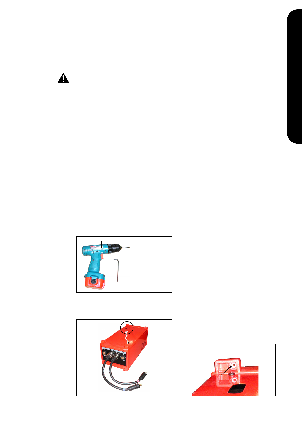
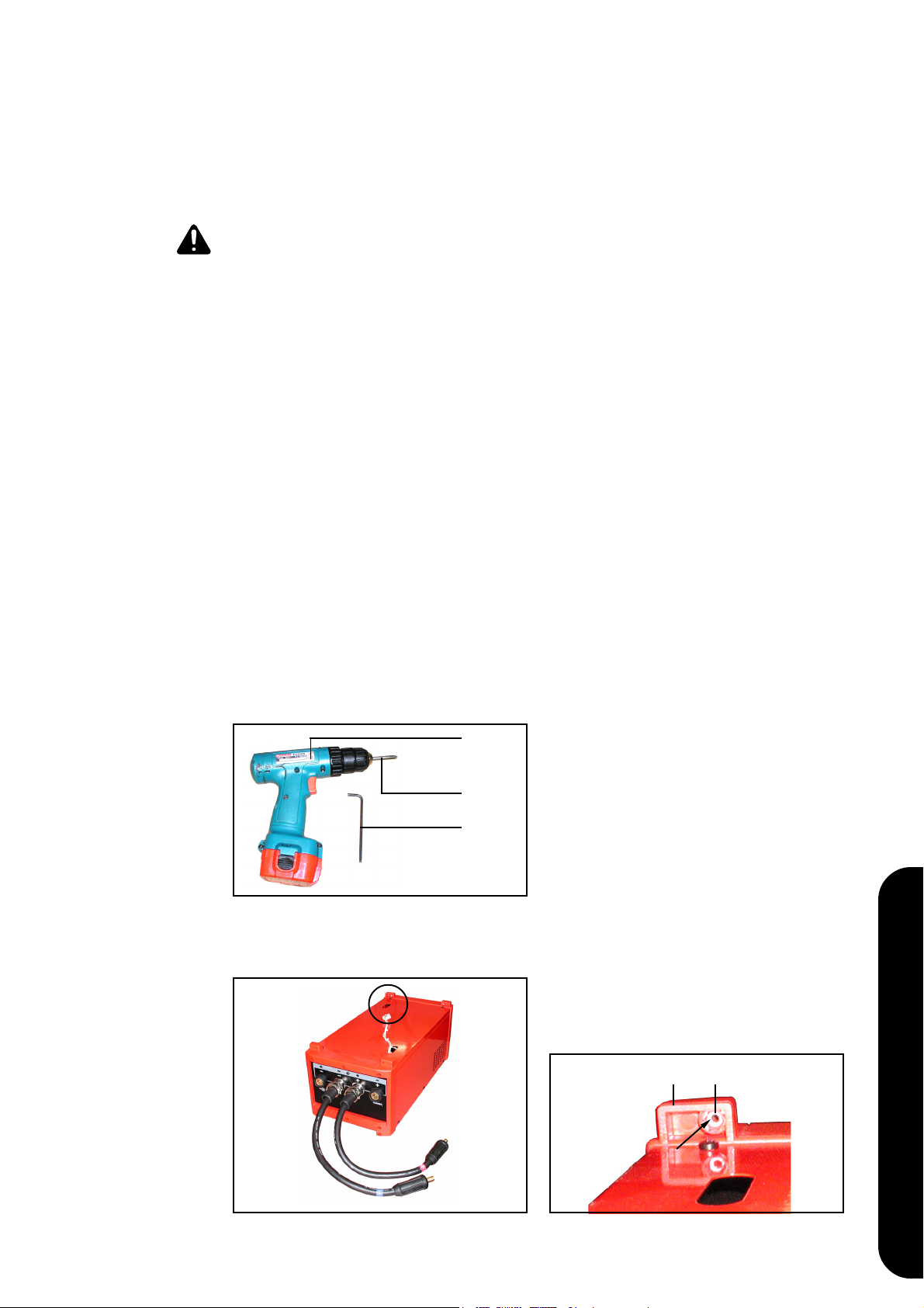
Abb.1 Werkzeuge
Detail X
(A)
(B)
(C)
(A) Akku-Schrauber
(B) Bit-Einsatz TX 25
(C) Innensechskantschlüssel Größe 4
1. 4 x Sechskantmutter (a) in KunststoffLasche (b) am Polwender-Gehäuse
einsetzen
(a)
(b)
Abb.2 Sechskantmutter einsetzen
Abb.3 Detail X - Ansicht
1
1
Page 4

Vorbereitungen
an der Stromquelle
(A) (c)
Abb.4 Abdeckung für Kühlkreis-Stecker entfernen
1. Software-Version der Stromquelle
feststellen:
- Stromquelle einschalten
- Tasten Setup/Store und Parame-
teranwahl gleichzeitig drücken
- aktuelle Software-Version wird
angezeigt
(siehe auch Bedienungsanleitung der
Stromquelle)
2. Rechtes Seitenteil entfernen
3. Wenn die Stromquelle nicht mit der
Software OFFICIAL UST V2.81.1
ausgestattet ist:
Software-Update durchführen
4. Stromquelle umlegen
5. Abdeckung für Kühlgerät-Stecker (c)
mittels Akku-Schrauber (A) entfernen
Abdeckung und Schrauben werden
nicht mehr benötigt
Stromquelle und
Polwender
verbinden
(e) (d)
Abb.5 Stromquelle aufsetzen
Achtung! Kippgefahr!
Stromquelle beim Aufsetzen auf den
Polwender festhalten.
1. Stromquelle schräg auf Polwender
aufsetzen
2. Kabel (d) durch Öffnung (e) der
Stromquelle fädeln
3. Stromquelle auf Polwender aufsetzen,
sodaß die Kunststoff-Laschen des
Polwenders innerhalb der Stromquelle
sind
4. Dichtung für Durchführung (f) mit
Kabel (d) in die untere Durchführung
(g) der Stromquelle einsetzen
(g) (f) (d)
Abb.6 Kabel in Durchführung einsetzen
22
Page 5
Stromquelle und
Polwender
verbinden
(Fortsetzung)
(h) (d)
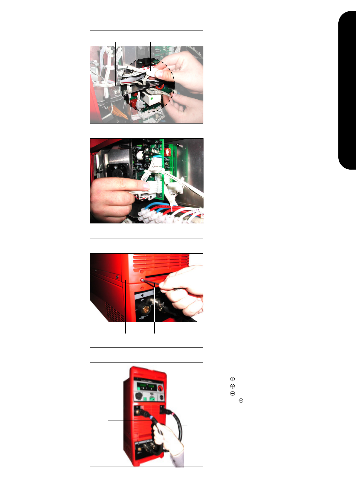
Abb.7 Kabel durch ovale Ausnehmung fädeln
5. Kabel (d) durch die ovale Ausnehmung (h) am Trennblech fädeln
DE
DEUTSCH
6. Molex-Stecker von Kabel (d) am Print
UST2A / X10 (i) anstecken
Der Print UST2A befindet sich oberhalb des Trennbleches beim Lüfter.
(d) (i)
Abb.8 Kabel am Print UST2A anstecken
(C)(j)
Abb.9 Innensechskantschrauben einsetzen
7. Seitenteil rechts montieren
8. 4 x Innensechskantschrauben M5x40
(j) einsetzen
9. Innensechskantschrauben (j) mittels
Innensechskantschlüssel (C) festziehen
10. Polwender-Kabel an der Stromquelle
anstecken:
- -Kabel (k) mit roter Markierung an
-Strombuchse der Stromquelle
- -Kabel (l) mit blauer Markierung
an -Strombuchse der Stromquelle
(l)
(k)
Abb.10 Polwender-Kabel an Stromquelle anstecken
3
3
Page 6

44
Page 7

Installation instructions: Polarity reverser
General remarks
Requirements
Components
The optional polarity reverser makes it easy to switch over the polarity used in MMA
(rod-electrode) welding.
At the moment, the polarity reverser can only be installed in the factory.
Warning! The following modifications may only be performed by suitably trained and
skilled electricians!
Before starting the installation job:
- shift the mains switch of the power source to the “0” position
- unplug the power source from the mains
- if the power source is mounted on a trolley or similar device:
detatch the power source from the trolley before starting the modification
Observe the safety regulations in the Operating Instructions of the power source.
In order to use the polarity reverser with the TransPocket 4000 CEL / 5000 CEL, the
following are required:
- power source with OFFICIAL UST V2.81.1 software
- TR 3000 remote control unit
Polarity reverser installation kit (4,045,883),
consisting of
1 polarity reverser
4 hexagonal socket head screw, M5x40
4 hexagonal nut, M5
EN
ENGLISH
Tools required
Preparations on
the polarity
reverser
Fig.1 Tools
Close-up X
(A)
(B)
(C)
(A) Battery-operated power screwdriver
(B) Bit insert TX 25
(C) Size 4 hexagon socket screw key
1. Insert a hexagonal nut (a) into each of
the 4 plastic lugs (b) on the housing of
the polarity reverser
(a)(b)
Fig.2 Insert hexagonal nut
Fig.3 Close-up view of X
55
Page 8

Preparations on
the power source
(A) (c)
1. Find out the software version of your
power source:
- Switch on the power source
- Simultaneously press the Setup/
Store and Parameter Selection
buttons
- The current software version is
displayed
(see also the Operating Instructions of
the power source)
2. Remove the right side panel
Attaching the
power source to
the polarity
reverser
Fig.4 Removing the cover for the cooling-unit
plug
(e) (d)
Fig.5 Placing the power source onto the polarity
reverser
3. If the power source is not equipped
with the OFFICIAL UST V2.81.1
software:
Carry out a software update
4. Place the power source on its side
5. Using the battery-operated power
screwdriver (A), remove the cover for
the cooling-unit plug (c)
The cover and screws are no longer
needed
Warning! Danger of unit toppling!
When placing the power source
onto the polarity reverser, hold it
firmly.
1. Place the power source diagonally
across the top of the polarity reverser
2. Thread the cable (d) through the
opening (e) in the underside of the
power source
3. Position the power source on the
polarity reverser in such a way that
the plastic lugs of the polarity reverser
are inside the power source
4. Insert the lead-through seal (f) with
the cable (d) into the bottom leadthrough (g) of the power source
(g) (f) (d)
Fig.6 Inserting the cable into the lead-through
66
Page 9

Attaching the
power source to
the polarity
reverser
(continued)
(h) (d)
Fig.7 Threading the cable through the oval
recess
5. Thread the cable (d) through the oval
recess (h) in the partition plate
6. Plug the Molex plug of the cable (d)
onto p.c.-board UST2A / X10 (i)
The UST2A p.c.-board is situated
above the partition plate, near the fan.
(d) (i)
Fig.8 Plugging the cable onto the UST2A board
(C)(j)
Fig.9 Inserting the hexagonal socket head
screws
(l)
(k)
7. Replace the right side panel
8. Insert the 4 hexagonal socket head
screws M5x40 (j)
9. Tighten the hexagonal socket head
screws (j) with the hexagon socket
screw key (C)
10. Plug the polarity reverser cable into
the power source, as follows:
- the red-marked cable (k) into the
current socket on the power
source;
- the blue-marked cable (l) into the
current socket on the power
source
EN
ENGLISH
Fig.10 Plugging the polarity-reverser cable into
the power source
77
Page 10

88
Page 11
Instructions de montage inverseur de pôles
Généralités
Conditions à
remplir
Composants
L’option inverseur de pôles sert à inverser simplement les pôles lors du soudage aux
électrodes barres.
Attention! Le montage suivant ne doit être réalisé que par du personnel expert!
Observer les points suivants avant le montage
- Commuter l’interrupteur d’alimenation de la source de courant en position «O»
- Tirer la fiche secteur de la source de courant
- Dans le cas où la source de courant serait montée sur un chariot ou un dispositif
semblable, séparer la source de courant du chariot avant la transformation.
Observez les consignes de sécurité dans la notice d’instructions de votre source de
courant
Ce qui suit est nécessaire pour la marche de l’inverseur de pôles avec le Transpocket
4000 CEL / 5000 CEL
- Source de courant avec logiciel OFFICIAL UST V2.81.1
- Télécommande TR 3000
Set de montage inverseur de pôles (4, 045, 883)
composé de
1 inverseur de pôles
4 vis à six pans creux M5x40
4 écrous à six pans M5
Outillage nécessaire
Préparatifs sur
l’inverseur de
pôles
Fig. 1 Outillage
Détail X
(A)
(B)
(C)
(A) Visseur d’accumulateurs
(B) Mèche Bit TX 25
(C) Clé mâle coudée de 4
1. Placer l’écrou à six pans (a) dans
l’éclisse (b) du boîtier de l’inverseur, 4
fois
(a)
(b)
FR
FRANÇAIS
Fig. 2 Mise en place de l’écrou à six pans
Fig. 3 Détail X - vue
99
Page 12

Préparatifs sur la
source de courant
Relier la source
de courant à
l’inverseur de
pôles
(A) (c)
Fig. 4 Retirer le recouvrement de la fiche de circuit
de refroidissement
(e) (d)
Fig. 5 Mise en place de la source de courant
1. Identifier la version de logiciel de la
source de courant:
- Mettre en marche la source de
courant
- Enfoncer simultanément les
touches Setup/Store et sélection
de paramètres
- La version actuelle du logiciel
s’affiche
(cf. aussi la notice d’instructions de la
source de courant)
2. Retirer la partie latérale de droite
3. Si la source de courant n’est pas
munie du logiciel OFFICIAL UST V2
81.1, faire une mise à jour
4. Renverser la source de courant
5. Retirer le recouvrement de la fiche de
l’appareil refroidisseur 8c) avec le
visseur à accumulateurs
On n’a plus besoin du recouvrement
et des vis
Attention! Danger de basculement!
Maintenir la source de courant en la
posant sur l’inverseur de pôles!
1. Placer la source de courant transversalement sur l’inverseur
2. Faire passer le câble (d) à travers
l’ouverture de la source de courant
3. Placer la source de courant sur
l’inverseur de manière à ce que les
éclisses en plastique de l’inverseur
soient à l’intérieur de la source de
courant
(g) (f) (d)
Fig. 6 Placer le câble dans la traversée
1010
4. Placer le joint pour la traversée (f)
avec le câble dans la traversée
inférieure (g) de la source de courant
Page 13

Relier la source
de courant à
l’inverseur de
pôles
(suite)
(h) (d)
Fig. 7 Faire passer le câble à travers l’entaille ovale
5. Faire passer le câble (d) à travers
l’entaille ovale (h) de la tôle séparatrice
6. Ficher la fiche Molex du câble (d) à la
plaquette à circuits imprimés UST2A /
X10 (i)
La plaquette à circuits imprimés
UST2A se trouve au-dessus de la tôle
séparatrice, près du ventilateur
(d) (i)
Fig 8 Ficher le câble sur la plaquette à circuits
imprimés
(C)(j)
Fig 9 Placer les vis à six pans creux
(l)
(k)
7. Monter la partie latérale droite
8. Placer les vis à six pans creux M5x40
quatre fois
9. Serrer les vis à six pans creux (j) à
l’aide de la clé mâle coudée (c)
10. Brancher le câble de l’inverseur sur la
source de courant
- câble -(k) avec repère rouge à la
douille de courant de la source
de courant
- câble -(l)avec repère bleu à la
douille de courant -de la source
de courant
FR
FRANÇAIS
Fig. 10 Brancher le câble de l’inverseur sur la source
de courant
1111
Page 14

Page 15

Page 16

FRONIUS INTERNATIONAL GMBH
Froniusplatz 1, A-4600 Wels, Austria
Tel: +43 (0)7242 241-0, Fax: +43 (0)7242 241-3940
E-Mail: sales@fronius.com
www.fronius.com
Under http://www.fronius.com/addresses you will find all addresses
www.fronius.com/addresses
of our Sales & service partners and Locations.
ud_fr_st_so_00082 012011
 Loading...