

Page 1

Fronius prints on elemental chlorine free paper (ECF) sourced from certified sustainable forests (FSC).
/ Perfect Charging / Perfect Welding / Solar Energy
PM43 PullMig-Regler
PM43 PullMig controller
Installationsanleitung
DE
Roboter-Option
Installation instructions
EN
Robot option
42,0410,1760 013-09092021
Page 2

Page 3

Allgemeines
(1) (2)
(3)
(4)
(5)
(6)(7)
(9) (8)
(10)
DE
ESD-Bestimmungen
Lieferumfang
HINWEIS!
Beachten Sie beim Umgang mit elektronischen Bauteilen und Prints die ESDBestimmungen.
Dazu gehören vor allem ESD-gerechte
- Verpackungen
- Arbeitsflächen
- Böden
- Sitzgelegenheiten
- Erdungsmöglichkeiten
- Handhabung
Für einen unsachgemäß behandelten elektronischen Bauteil oder Print können keine
Garantie- und Gewährleistungsansprüche geltend gemacht werden.
(1) 1 Print PM43
(2) 1 Flachband-Kabel 150 mm, 26-polig
(3) 1 Kabelbaum 4-polig
(4) 1 Fächerscheibe
(5) 1 Sechskant-Mutter M5, SW 8 mm
(6) 1 Kunststoff-Distanz M4 x 10 mm
(7) 1 Messing-Distanz M4 x 10 mm mit Gewindezapfen
(8) 1 Messing-Distanz M4 x 30 mm
(9) 2 Kabelbinder
(10) 1 Adapter-Kabelbaum
3
Page 4

(11)
(11) 1 Kabelbaum 2-polig (nur bei VR
4000 Case notwendig)
Erforderliche
Werkzeuge und
Hilfsmittel
- Torx-Schraubendreher TX25
- Gabelschlüssel SW 8 mm
- Gabelschlüssel SW 7 mm
- Seitenschneider
- Torx-Schraubendreher TX8 (nur für VR 4000 Case)
4
Page 5

PM43 Pullmig-Regler in Steuergerät VR für IGM einbauen
Sicherheit
WARNUNG!
Gefahr durch Fehlbedienung und fehlerhaft durchgeführte Arbeiten.
Schwerwiegende Personen- und Sachschäden können die Folge sein.
Alle in diesem Dokument beschriebenen Arbeiten und Funktionen dürfen nur von
▶
geschultem Fachpersonal ausgeführt werden.
Dieses Dokument lesen und verstehen.
▶
Sämtliche Bedienungsanleitungen der Systemkomponenten, insbesondere Sicher-
▶
heitsvorschriften lesen und verstehen.
WARNUNG!
Gefahr durch elektrischen Strom.
Schwerwiegende Personen- und Sachschäden können die Folge sein.
Netzschalter der Stromquelle in Stellung - O - schalten und die Stromquelle vom
▶
Netz trennen
Alle beteiligten Geräte und Komponenten gegen Wiedereinschalten sichern.
▶
Nach dem Öffnen des Gerätes mit Hilfe eines geeigneten Messgerätes sicherstel-
▶
len, dass elektrisch geladene Bauteile (beispielsweise Kondensatoren) entladen
sind.
DE
WARNUNG!
Gefahr durch elektrischen Strom wegen unzureichender Schutzleiter-Verbindung.
Schwerwiegende Personen- und Sachschäden können die Folge sein.
Immer die originalen Gehäuse-Schrauben in der ursprünglichen Anzahl verwenden.
▶
VORSICHT!
Verletzungsgefahr durch heiße Systemkomponenten.
Schwere Verbrühungen können die Folge sein.
Vor Beginn der Arbeiten alle heißen Systemkomponenten auf Zimmertemperatur
▶
(+25 °C, +77 °F) abkühlen lassen, beispielsweise: Kühlmittel, wassergekühlte Systemkomponenten, Antriebsmotor des Drahtvorschubes
Voraussetzung Für den Einbau des Einbau-Sets PM43 Pullmig-Regler in das Steuergerät VR für IGM,
muss die Option SR43 IGM im Steuergerät VR für IGM eingebaut sein.
Vorbereitung
Alle am Steuergerät VR für IGM angeschlossenen Systemkomponenten abschließen
1
TX25 Schrauben bei Gehäusedeckel und Seitenteilen entfernen
2
Gehäusedeckel und Seitenteile vom Steuergerät VR für IGM entfernen
3
5
Page 6

(1) (2) (3)
Kabelbaum (2) am Print PM43 / X2 (1)
(4)
(1)
(2)
(3)
(4)
(5)
4
anstecken
Flachband-Kabel (3) am Print PM43 /
5
X4 (1) anstecken
Messing-Distanz M4 x 30 mm (4)
6
gemäß Abbildung am Print SR43 aufschrauben, SW 7 mm
Print PM43 Pullmig-Regler für
IGM in Steuergerät VR für IGM
einbauen
Stecker vom Flachband-Kabel (4) am
1
Print SR43 anstecken
Print PM43 (2) auf Print SR43 aufset-
2
zen
Print PM43 (2) festschrauben mittels:
3
- Kunststoff-Distanz M4 x 10 mm
(5), SW 8 mm
- Messing-Distanz M4 x 10 mm mit
Gewindezapfen (3), SW 7 mm
- Fächerscheibe und SechskantMutter M5 (1), SW 8 mm
6
Page 7

(6)
Kabelbaum (6) vom Print SR43 / X10
(6)
(7)
(8) (9) (10)
4
abstecken und ...
... Kabelbaum (6) am Print PM43 / X1
5
anstecken
Kabelbaum (7) vom Print PM43 am
6
Print SR 43 / X10 anstecken
DE
Abschließende
Tätigkeiten
Freies Kabel (8) vom Einbau-Set
7
SR43 für IGM am Print PM43 / X3
anstecken
Kabel mittels Kabelbinder (9) und (10)
8
fixieren
HINWEIS!
Beim Montieren der Seitenteile und des Gehäusedeckels darauf achten, dass
Kabel nicht eingeklemmt oder auf andere Weise beschädigt werden.
Seitenteile und Gehäusedeckel am Steuergerät VR für IGM montieren
1
Steuergerät VR für IGM wieder in das Schweißsystem integrieren
2
7
Page 8

PM43 Pullmig-Regler in VR 1550 einbauen
Sicherheit
WARNUNG!
Gefahr durch Fehlbedienung und fehlerhaft durchgeführte Arbeiten.
Schwerwiegende Personen- und Sachschäden können die Folge sein.
Alle in diesem Dokument beschriebenen Arbeiten und Funktionen dürfen nur von
▶
geschultem Fachpersonal ausgeführt werden.
Dieses Dokument lesen und verstehen.
▶
Sämtliche Bedienungsanleitungen der Systemkomponenten, insbesondere Sicher-
▶
heitsvorschriften lesen und verstehen.
WARNUNG!
Gefahr durch elektrischen Strom.
Schwerwiegende Personen- und Sachschäden können die Folge sein.
Netzschalter der Stromquelle in Stellung - O - schalten und die Stromquelle vom
▶
Netz trennen
Alle beteiligten Geräte und Komponenten gegen Wiedereinschalten sichern.
▶
Nach dem Öffnen des Gerätes mit Hilfe eines geeigneten Messgerätes sicherstel-
▶
len, dass elektrisch geladene Bauteile (beispielsweise Kondensatoren) entladen
sind.
WARNUNG!
Vorbereitung
Gefahr durch elektrischen Strom wegen unzureichender Schutzleiter-Verbindung.
Schwerwiegende Personen- und Sachschäden können die Folge sein.
Immer die originalen Gehäuse-Schrauben in der ursprünglichen Anzahl verwenden.
▶
VORSICHT!
Verletzungsgefahr durch heiße Systemkomponenten.
Schwere Verbrühungen können die Folge sein.
Vor Beginn der Arbeiten alle heißen Systemkomponenten auf Zimmertemperatur
▶
(+25 °C, +77 °F) abkühlen lassen, beispielsweise: Kühlmittel, wassergekühlte Systemkomponenten, Antriebsmotor des Drahtvorschubes
Alle am VR 1550 angeschlossenen Systemkomponenten abschließen
1
Rechten Seitenteil vom VR 1550 entfernen (von vorne gesehen)
2
8
Page 9

(1) (2) (3)
Kabelbaum (2) am Print PM43 / X2 (1)
(4)
(1) (2) (3) (4) (5) (6)
3
anstecken
Flachband-Kabel (3) am Print PM43 /
4
X4 (1) anstecken
Kunststoff-Distanz von Position (4)
5
entfernen, SW 8 mm
An der gleichen Position (4) die Mes-
6
sing-Distanz M4 x 30 mm aufschrauben, SW 7 mm
DE
Print PM43 Pullmig-Regler in VR
1550 einbauen
Stecker vom Flachband-Kabel (2) am
1
Print SR43 anstecken
Print PM43 (4) auf Print SR43 aufset-
2
zen
Print PM43 (4) festschrauben mittels:
3
- Kunststoff-Distanz M4 x 10 mm
(1), SW 8 mm
- Messing-Distanz M4 x 10 mm mit
Gewindezapfen (3), SW 7 mm
- Fächerscheibe und SechskantMutter M5 (5), SW 8 mm
Kabelbaum (6) vom Print SR43 / X11
4
abstecken und ...
9
Page 10

(6)(7)
... Kabelbaum (6) am Print PM43 / X1
5
anstecken
Kabelbaum (7) vom Print PM43 am
6
Print SR 43 / X11 anstecken
Kabel mittels Kabelbinder fixieren
7
Abschließende
Tätigkeiten
HINWEIS!
Beim Montieren des Seitenteils darauf achten, dass Kabel nicht eingeklemmt oder
auf andere Weise beschädigt werden.
Rechten Seitenteil des Drahtvorschubes montieren
1
Drahtvorschub wieder in das Schweißsystem integrieren
2
10
Page 11
PM43 Pullmig-Regler in VR 4000 Case einbauen
DE
Sicherheit
WARNUNG!
Gefahr durch Fehlbedienung und fehlerhaft durchgeführte Arbeiten.
Schwerwiegende Personen- und Sachschäden können die Folge sein.
Alle in diesem Dokument beschriebenen Arbeiten und Funktionen dürfen nur von
▶
geschultem Fachpersonal ausgeführt werden.
Dieses Dokument lesen und verstehen.
▶
Sämtliche Bedienungsanleitungen der Systemkomponenten, insbesondere Sicher-
▶
heitsvorschriften lesen und verstehen.
WARNUNG!
Gefahr durch elektrischen Strom.
Schwerwiegende Personen- und Sachschäden können die Folge sein.
Netzschalter der Stromquelle in Stellung - O - schalten und die Stromquelle vom
▶
Netz trennen
Alle beteiligten Geräte und Komponenten gegen Wiedereinschalten sichern.
▶
Nach dem Öffnen des Gerätes mit Hilfe eines geeigneten Messgerätes sicherstel-
▶
len, dass elektrisch geladene Bauteile (beispielsweise Kondensatoren) entladen
sind.
WARNUNG!
Vorbereitung
Gefahr durch elektrischen Strom wegen unzureichender Schutzleiter-Verbindung.
Schwerwiegende Personen- und Sachschäden können die Folge sein.
Immer die originalen Gehäuse-Schrauben in der ursprünglichen Anzahl verwenden.
▶
VORSICHT!
Verletzungsgefahr durch heiße Systemkomponenten.
Schwere Verbrühungen können die Folge sein.
Vor Beginn der Arbeiten alle heißen Systemkomponenten auf Zimmertemperatur
▶
(+25 °C, +77 °F) abkühlen lassen, beispielsweise: Kühlmittel, wassergekühlte Systemkomponenten, Antriebsmotor des Drahtvorschubes
Alle am Drahtvorschub angeschlossenen Systemkomponenten abschließen
1
Rechten Seitenteil vom Drahtvorschub entfernen (von vorne gesehen)
2
11
Page 12

(1)
(2)
(3)
(4)
2-poligen Kabelbaum (1) am Print
(5)
(3) (4)(1)(2)
3
PM43 / X2 (4) anstecken
4-poligen Kabelbaum (2) am Print
4
PM43 / X3 (4) anstecken
Flachband-Kabel (3) am Print PM43 /
5
X4 (4) anstecken
Kunststoff-Distanz von Position (5)
6
entfernen, SW 8 mm
An der gleichen Position (5) die Mes-
7
sing-Distanz M4 x 30 mm aufschrauben, SW 7 mm
Print PM43 Pullmig-Regler in VR
4000 Case einbauen
Stecker vom Flachband-Kabel (1) des Print PM43 (2) an Buchse (3) des Print SR43
1
(4) anstecken
12
Page 13

(5) (2) (6) (4) (8)(7)
Print PM43 (2) auf Print SR43 (4) auf-
(9) (10) (11)
(12) (13)
2
setzen
Print PM43 (2) festschrauben mittels:
3
- Kunststoff-Distanz M4 x 10 mm
(5), SW 8 mm
- Messing-Distanz M4 x 10 mm mit
Gewindezapfen (6), SW 7 mm
- Fächerscheibe und SechskantMutter M5 (7), SW 8 mm
Kabelbaum (8) vom Print SR43 / X11
4
abstecken und ...
... Kabelbaum (8) am Print PM43 / X1
5
(9) anstecken
4-poligen Kabelbaum (10) vom Print
6
PM43 am Print SR 43 / X11 (11)
anstecken
DE
2 Schrauben TX 8 (12) vom Sockel
7
(13) lösen
Sockel (13) aus dem Gehäuse des
8
Drahtvorschubes ziehen
13
Page 14

(14)
Kabelbaum (14) durch das Gehäuse
(15) (16)
(17)
9
des Drahtvorschubes nach vorne zum
Sockel (13) legen
Pins vom Kabelbaum (14) laut deren
10
Beschriftung am Sockel 13
anschließen
- (15) = X8/6
- (16) = X8/1
Kabel (14) ordnungsgemäß verlegen
11
und mittels Kabelbinder am bereits
bestehenden Kabelbaum fixieren
Kabelbaum (17) vom Print SR43 / X3
12
abstecken
14
Page 15

(17)
(18)
Kabelbaum (17) mit dem Adapter-
13
Kabelbaum (18) zusammenstecken
Adapter-Kabelbaum (18) am Print
14
SR43 / X3 anstecken
DE
Abschließende
Tätigkeiten
HINWEIS!
Beim Montieren des Seitenteils darauf achten, dass Kabel nicht eingeklemmt oder
auf andere Weise beschädigt werden.
Rechten Seitenteil des Drahtvorschubes montieren
1
Drahtvorschub wieder in das Schweißsystem integrieren
2
15
Page 16

Schaltplan
3
1
1m
2
4m
4
+A1-X17
3m
2m
7
6
5
4
3
2
1
+A1-X5
8
12
13m
13
14m
14
+A1-X4
7m
7
8m
8
9m
9
10m
10
11m
11
12m
5
6m
6
2
1
3m
3
4m
4
5m
2m
1m
4
3
2
1
+A1-X1
6
5
8
7
4
5
3
1
2m
1m
2
3m
6m
6
+A1-X7
4m
5m
3
1
1m
2
4m
4
+A1-X10
3m
2m
+A1-X11
3
1
1m
2
4m
4
3m
2m
1
2
1
+A2-X3
3
4
+A1-X13
1
2
1
-V1
2
1
-X9
J
I
H
G
F
E
D
C
B
A
-X10
N
M
L
K
J
I
H
G
F
E
D
C
B
A
-X2 -X3
-X28
T
S
R
P
N
M
L
K
J
H
G
F
E
D
C
B
A
+A3-X2
16
16m
15
15m
14
14m
13
13m
12
12m
11
11m
10
10m
9
9m
8
8m
7
7m
6
6m
5
5m
4
4m
3
3m
1
2
1m
2m
+A3-X1
4
4m
2
1m
1
3
3m
2m
+A3-X4
4
4m
2
1m
1
3
3m
2m
+A3-X3
4
4m
2
1m
1
3
3m
2m
+A3-X5
2
1
1
2
-R1
4
321
+A1 SR43A 4,070,905
PP MOTOR +
PP MOTOR -
WIRE IN
GND
REAL VALVE PP IN
WIRE RETRACT
REAL VALVE PP GND
GAS CHECK
BLOW OUT +24V
GAS PRESSURE
GASVALVE +24V
GASVALVE GND
VR MOTOR +
BLOW OUT GND
VR MOTOR -
REAL VALVE VR GND
REAL VALVE VR IN
GND
GND
GND
N.C.
N.C.
CAT GND
CAT +24V
N.C. (GAS NOZZLE)
N.C.
REAL VALVE PP GND
GAS CHECK
WIRE RETRACT
REAL VALVE PP IN
GND
WIRE IN
PP MOTOR -
PP MOTOR +
TXDL
+55V
RXDL
+24V
+55V
TXDH
RXDH
N.C.
MOTOR -
N.C.
MOTOR +
+24V (GAS)
CFM -
VD - ANA -
GND (R.V.)
GND (GAS)
CFM +
VD- ANA +
REAL VALVE IN
+24V (BLOW OFF)
CAT
GAS PREASSURE
WIRE END
WIRE IN
WIRE RETRACT
RESERVE
BLOW OUT
GND (CAT)
GND (WIRE END)
REAl VALVE
GND
GAS CHECK
+24V (RESERVE)
GND
+5V
POWER +
POWER -
GND
+5V
ARC +
ARC -
+55V
+55V
GND
GND
+24V
RXDL
RXDH
GND
TXDL
TXDH
+55V
+55V
GND
GND
R
O
T
OM
LEE
R
-
E
DS
R
OT
O
M
G
I
M
L
L
U
P
/
HS
U
P
REMOTE CONTROL
CURRENT
SHUNT
+A3 FIL43 4,071,266
PM Mot +
PM Mot -
NC
NC
VR Mot +
VR Mot -
NC
NC
+55V
+55V
GND
GND
+55V
+55V
PM43 Mot -
PM43 Mot +
+5V
GND A
NC
SR43 Mot +
NC
NC
GND
GND
Selection
GND A
NC
SR43 Mot -
EARTH
MEASUREMENT
16
Page 17

General
(1) (2)
(3)
(4)
(5)
(6)(7)
(9) (8)
(10)
ESD guidelines
Scope of supply
NOTE!
Observe ESD guidelines when handling electronic components and PC boards.
This primarily applies to ESD-compatible
- Packaging
- Work surfaces
- Floors
- Seating
- Earthing facilities
- Ease of handling
No guarantee or warranty claims can be made in respect of any improperly handled electronic component or PC board.
(1) 1 PM43 PC board
(2) 1 150 mm ribbon cable, 26-pin
(3) 1 4-pin cable harness
(4) 1 serrated washer
(5) 1 M5 hexagonal nut, size 8 mm
(6) 1 M4 x 10 mm plastic spacer
(7) 1 M4 x 10 mm brass spacer with threaded journal
(8) 1 M4 x 30 mm brass spacer
(9) 2 cable ties
(10) 1 adapter cable harness
EN
17
Page 18

(11)
(11) 1 2-pin cable harness (only requi-
red for VR 4000 Case)
Required tools
and materials
- TX25 Torx screwdriver
- Flat spanner, size 8 mm
- Flat spanner, size 7 mm
- Diagonal cutting pliers
- TX8 Torx screwdriver (for VR 4000 Case only)
18
Page 19
Install PM43 PullMig controller in control unit VR
for IGM
Safety
WARNING!
Danger due to incorrect operation and incorrectly performed work.
This can result in serious injury and damage to property.
All the work and functions described in this document must only be carried out by
▶
trained and qualified personnel.
Read and understand this document.
▶
Read and understand all the Operating Instructions for the system components,
▶
especially the safety rules.
WARNING!
Electrical current hazard.
This can result in serious injury and damage to property.
Turn the mains switch of the power source to the "O" position and disconnect the
▶
power source from the mains supply.
Secure all the devices and components involved to prevent unintentional restarting.
▶
After opening the device, use a suitable measuring instrument to check that electri-
▶
cally charged components (such as capacitors) have been discharged.
WARNING!
EN
Electrical current hazard caused by an inadequate ground conductor connection.
This can result in serious injury and damage to property.
Always use the original housing screws in the original quantity.
▶
CAUTION!
Risk of scalding from hot system components.
This can result in severe scalds.
Before starting work, allow all hot system components to cool down to room tempe-
▶
rature (+25 °C, +77 °F). For example: Coolant, water-cooled system components,
wirefeeder drive motor.
Requirements The SR43 IGM option must be installed in the VR IGM control unit before the PM43 Pull-
Mig controller installation kit can be installed in the VR IGM control unit.
Preparations
Disconnect all system components connected to the VR IGM control unit
1
Remove the TX25 screws from the housing cover and side panels
2
Remove the housing cover and side panels from the VR IGM control unit
3
19
Page 20

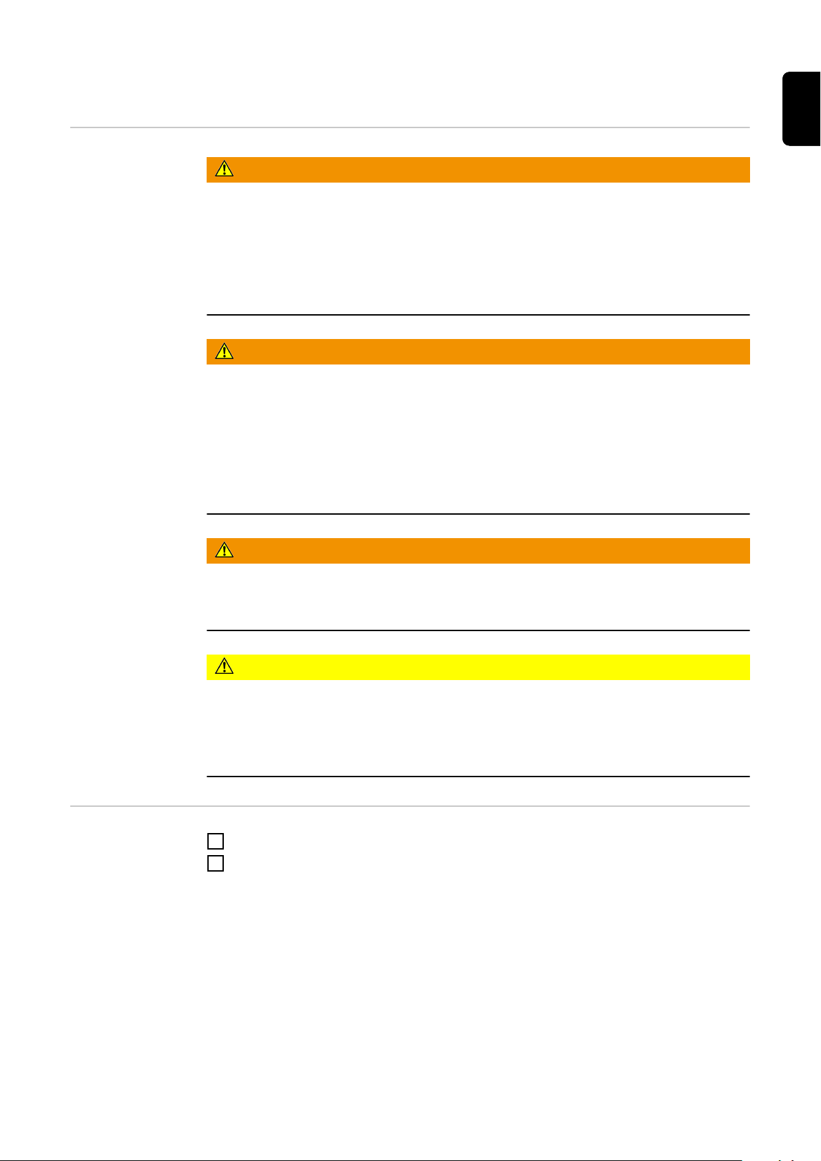
(1) (2) (3)
Connect the cable harness (2) to X2
(4)
(1)
(2)
(3)
(4)
(5)
4
on the PM43 PC board (1)
Connect the ribbon cable (3) to X4 on
5
the PM43 PC board (1)
Screw the M4 x 30 mm brass spacer
6
(4) onto the SR43 PC board as
shown, size 7 mm
Installing the
PM43 IGM PullMig controller PC
board in the VR
IGM control unit
Plug the ribbon cable plug (4) into the
1
SR43 PC board
Place the PM43 PC board (2) on the
2
SR43 PC board
Screw the PM43 PC board (2) in place
3
using:
- M4 x 10 mm plastic spacer (5),
size 8 mm
- M4 x 10 mm brass spacer with
threaded journal (3), size 7 mm
- Serrated washer and M5 hexagonal nut (1), size 8 mm
20
Page 21

(6)
Disconnect the cable harness (6) from
(6)
(7)
(8) (9) (10)
4
X10 on the SR43 PC board and...
... connect the cable harness (6) to X1
5
on the PM43 PC board
Connect the cable harness (7) from
6
the PM43 PC board to X10 on the
SR43 PC board
EN
And finally...
NOTE!
When fitting the side panels and housing cover, ensure that cables are not trapped
or damaged in any way.
Connect the free cable (8) from the
7
SR43 IGM installation kit to X3 on the
PM43 PC board
Secure the cables in place using cable
8
ties (9) and (10)
Fit the side panels and housing cover to the VR IGM control unit
1
Reintegrate the VR IGM control unit in the welding system
2
21
Page 22

Install PM43 PullMig controller in the VR 1550
Safety
WARNING!
Danger due to incorrect operation and incorrectly performed work.
This can result in serious injury and damage to property.
All the work and functions described in this document must only be carried out by
▶
trained and qualified personnel.
Read and understand this document.
▶
Read and understand all the Operating Instructions for the system components,
▶
especially the safety rules.
WARNING!
Electrical current hazard.
This can result in serious injury and damage to property.
Turn the mains switch of the power source to the "O" position and disconnect the
▶
power source from the mains supply.
Secure all the devices and components involved to prevent unintentional restarting.
▶
After opening the device, use a suitable measuring instrument to check that electri-
▶
cally charged components (such as capacitors) have been discharged.
WARNING!
Preparations
Electrical current hazard caused by an inadequate ground conductor connection.
This can result in serious injury and damage to property.
Always use the original housing screws in the original quantity.
▶
CAUTION!
Risk of scalding from hot system components.
This can result in severe scalds.
Before starting work, allow all hot system components to cool down to room tempe-
▶
rature (+25 °C, +77 °F). For example: Coolant, water-cooled system components,
wirefeeder drive motor.
Disconnect all system components connected to the VR 1550
1
Remove the right side panel from the VR 1550 (as seen from the front)
2
22
Page 23

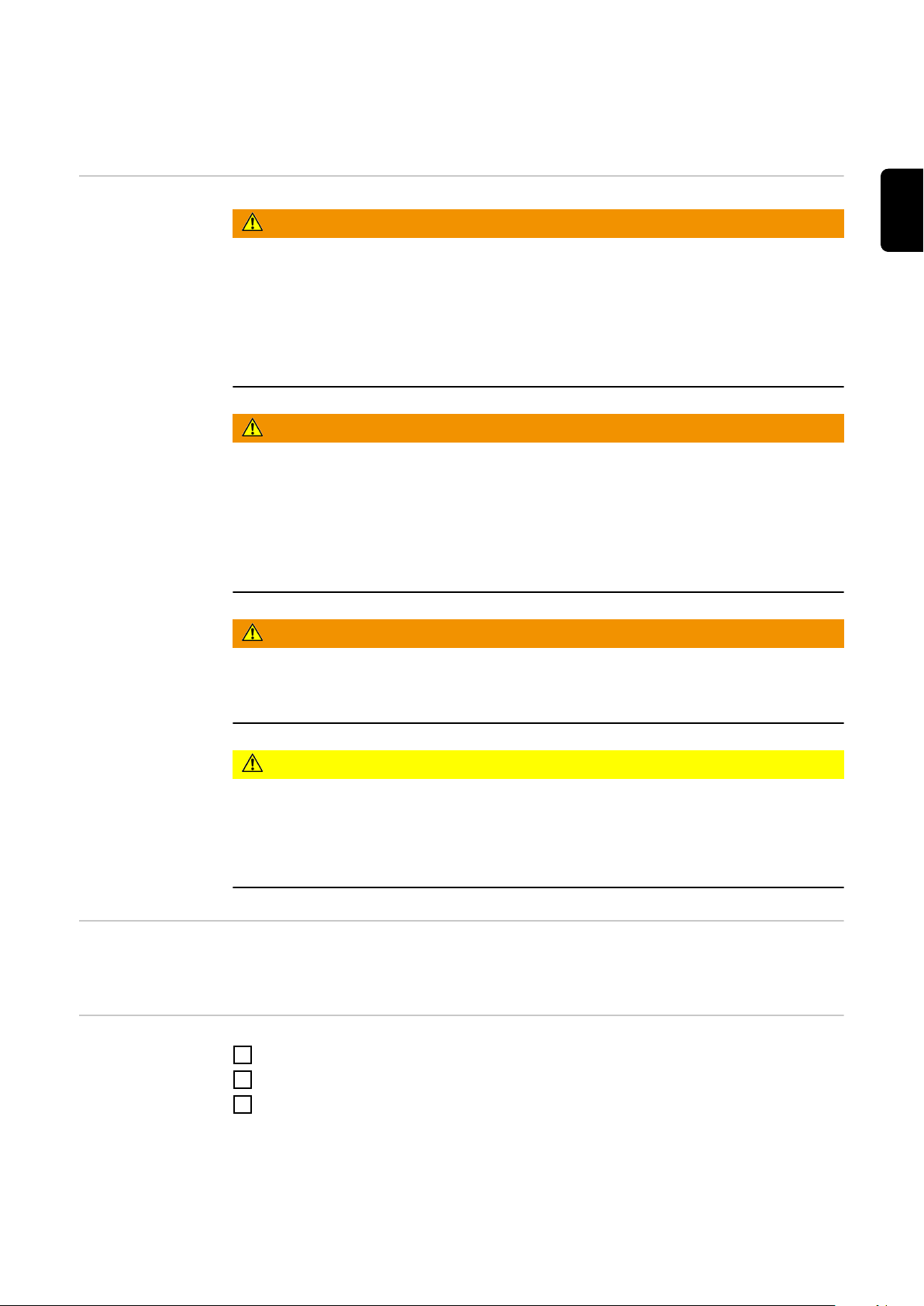
(1) (2) (3)
Connect the cable harness (2) to X2
(4)
(1) (2) (3) (4) (5) (6)
3
on the PM43 PC board (1)
Connect the ribbon cable (3) to X4 on
4
the PM43 PC board (1)
Remove the plastic spacer from posi-
5
tion (4), size 8 mm
Screw on the M4 x 30 mm brass spa-
6
cer in the same position (4), size 7
mm
EN
Installing the
PM43 PullMig
controller PC
board in the VR
1550
Plug the ribbon cable plug (2) into the
1
SR43 PC board
Place the PM43 PC board (4) on the
2
SR43 PC board
Screw the PM43 PC board (4) in place
3
using:
- M4 x 10 mm plastic spacer (1),
size 8 mm
- M4 x 10 mm brass spacer with
threaded journal (3), size 7 mm
- Serrated washer and M5 hexagonal nut (5), size 8 mm
Disconnect the cable harness (6) from
4
X11 on the SR43 PC board and...
23
Page 24

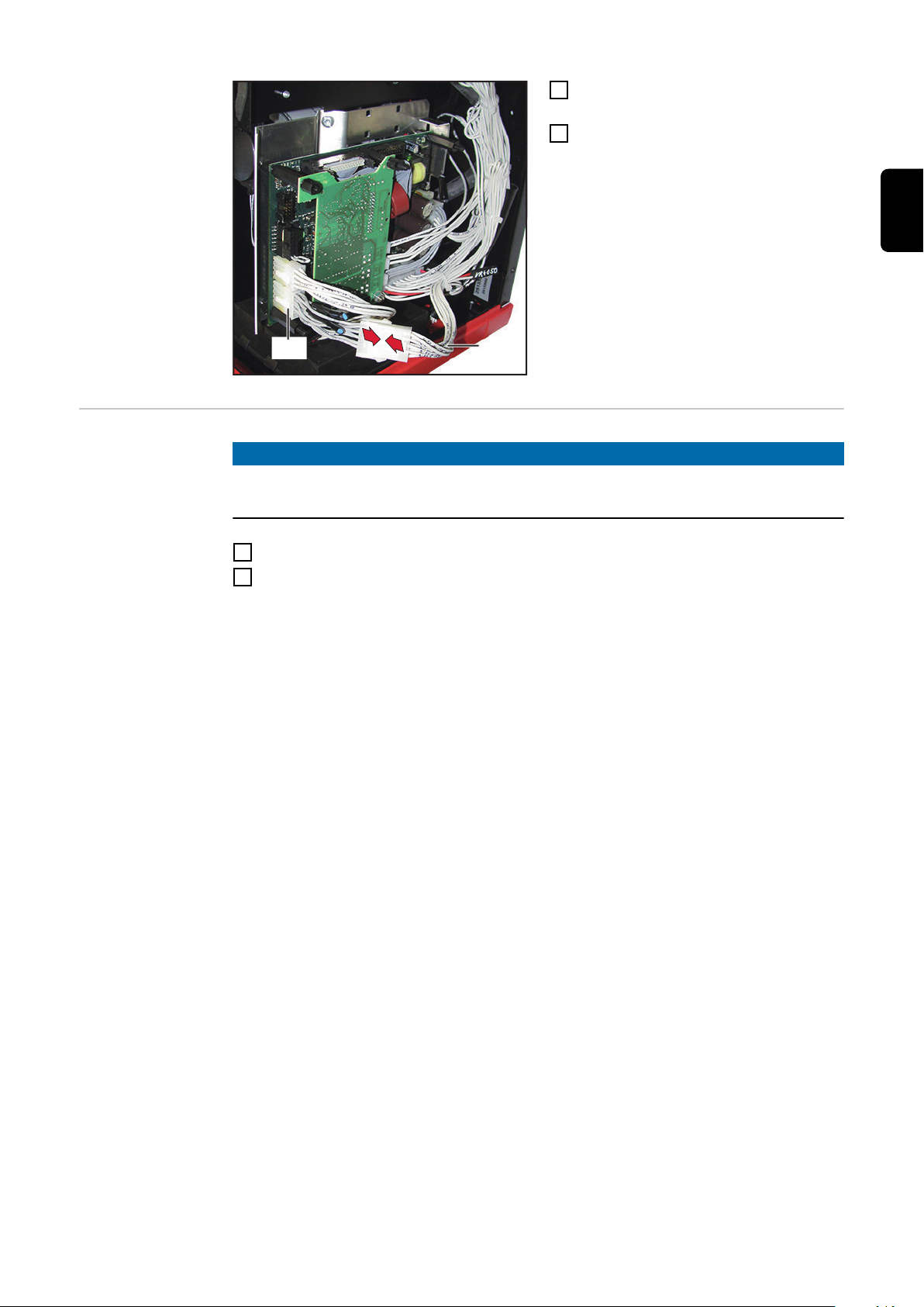
(6)(7)
... connect the cable harness (6) to X1
5
on the PM43 PC board
Connect the cable harness (7) from
6
the PM43 PC board to X11 on the
SR43 PC board
Secure the cables in place using cable
7
ties
And finally...
NOTE!
When fitting the side panel, ensure that cables are not trapped or damaged in any
way.
Attach the right side panel of the wirefeeder
1
Reintegrate the wirefeeder in the welding system
2
24
Page 25

Installing the PM43 PullMig controller in the VR
4000 Case
Safety
WARNING!
Danger due to incorrect operation and incorrectly performed work.
This can result in serious injury and damage to property.
All the work and functions described in this document must only be carried out by
▶
trained and qualified personnel.
Read and understand this document.
▶
Read and understand all the Operating Instructions for the system components,
▶
especially the safety rules.
WARNING!
Electrical current hazard.
This can result in serious injury and damage to property.
Turn the mains switch of the power source to the "O" position and disconnect the
▶
power source from the mains supply.
Secure all the devices and components involved to prevent unintentional restarting.
▶
After opening the device, use a suitable measuring instrument to check that electri-
▶
cally charged components (such as capacitors) have been discharged.
WARNING!
EN
Preparations
Electrical current hazard caused by an inadequate ground conductor connection.
This can result in serious injury and damage to property.
Always use the original housing screws in the original quantity.
▶
CAUTION!
Risk of scalding from hot system components.
This can result in severe scalds.
Before starting work, allow all hot system components to cool down to room tempe-
▶
rature (+25 °C, +77 °F). For example: Coolant, water-cooled system components,
wirefeeder drive motor.
Disconnect all system components connected to the wirefeeder
1
Remove the right side panel from the wirefeeder (as seen from the front)
2
25
Page 26
(1)
(2)
(3)
(4)
Connect the 2-pin cable harness (1) to
(5)
(3) (4)(1)(2)
3
X2 on the PM43 PC board (4)
Connect the 4-pin cable harness (2) to
4
X3 on the PM43 PC board (4)
Connect the ribbon cable (3) to X4 on
5
the PM43 PC board (4)
Remove the plastic spacer from posi-
6
tion (5), size 8 mm
Screw on the M4 x 30 mm brass spa-
7
cer in the same position (5), size 7
mm
Installing the
PM43 PullMig
controller PC
board in the VR
4000 Case
Plug the ribbon cable plug (1) on the PM43 PC board (2) into the socket (3) on the
1
SR43 PC board (4)
26
Page 27
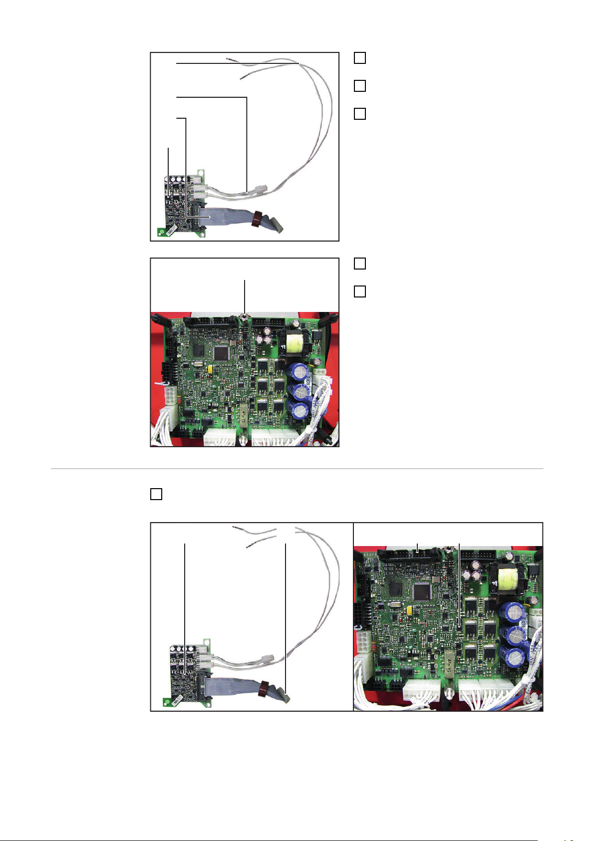
(5) (2) (6) (4) (8)(7)
Place the PM43 PC board (2) on the
(9) (10) (11)
(12) (13)
2
SR43 PC board (4)
Screw the PM43 PC board (2) in place
3
using:
- M4 x 10 mm plastic spacer (5),
size 8 mm
- M4 x 10 mm brass spacer with
threaded journal (6), size 7 mm
- Serrated washer and M5 hexagonal nut (7), size 8 mm
Disconnect the cable harness (8) from
4
X11 on the SR43 PC board and...
... connect the cable harness (8) to X1
5
on the PM43 PC board (9)
Connect the 4-pin cable harness (10)
6
from the PM43 PC board to X11 on
the SR43 PC board (11)
EN
Undo the two TX8 screws (12) on the
7
socket (13)
Pull the socket (13) out of the wirefee-
8
der housing
27
Page 28

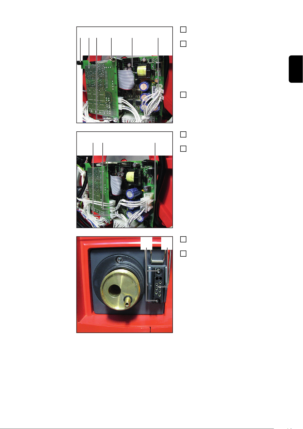
(14)
Route the cable harness (14) forwards
(15) (16)
(17)
9
through the wirefeeder housing
towards the socket (13)
Connect the cable harness pins (14)
10
to the socket (13) as indicated
- (15) = X8/6
- (16) = X8/1
Lay the cables (14) carefully and
11
secure them to the existing cable
harness using cable ties
Disconnect the cable harness (17)
12
from X3 on the SR43 PC board
28
Page 29
(17)
(18)
Connect the cable harness (17) with
13
the adapter cable harness (18)
Connect the adapter cable harness
14
(18) to X3 on the SR43 PC board
EN
And finally...
NOTE!
When fitting the side panel, ensure that cables are not trapped or damaged in any
way.
Attach the right side panel of the wirefeeder
1
Reintegrate the wirefeeder in the welding system
2
29
Page 30
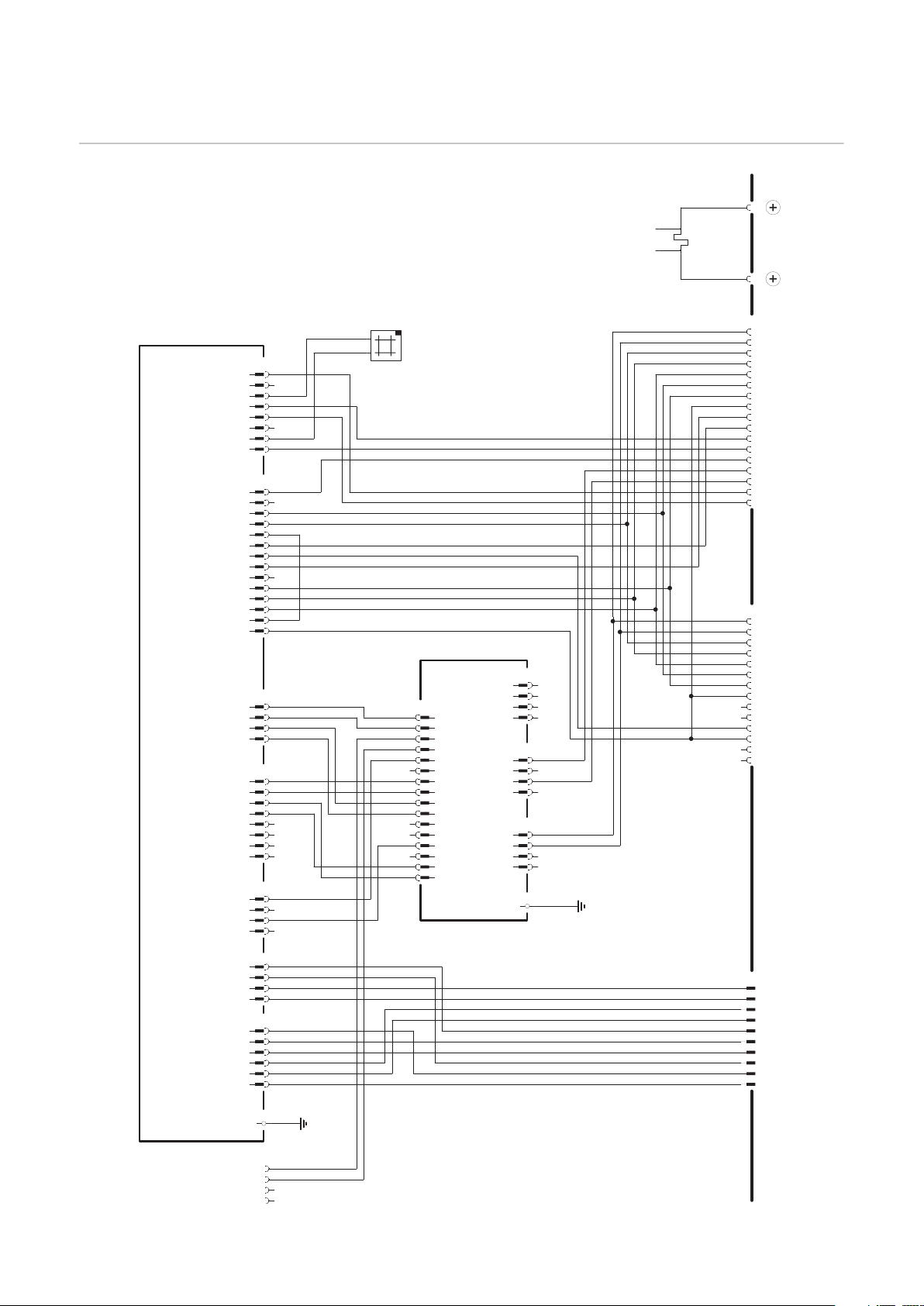
Circuit diagram
3
1
1m
2
4m
4
+A1-X17
3m
2m
7
6
5
4
3
2
1
+A1-X5
8
12
13m
13
14m
14
+A1-X4
7m
7
8m
8
9m
9
10m
10
11m
11
12m
5
6m
6
2
1
3m
3
4m
4
5m
2m
1m
4
3
2
1
+A1-X1
6
5
8
7
4
5
3
1
2m
1m
2
3m
6m
6
+A1-X7
4m
5m
3
1
1m
2
4m
4
+A1-X10
3m
2m
+A1-X11
3
1
1m
2
4m
4
3m
2m
1
2
1
+A2-X3
3
4
+A1-X13
1
2
1
-V1
2
1
-X9
J
I
H
G
F
E
D
C
B
A
-X10
N
M
L
K
J
I
H
G
F
E
D
C
B
A
-X2 -X3
-X28
T
S
R
P
N
M
L
K
J
H
G
F
E
D
C
B
A
+A3-X2
16
16m
15
15m
14
14m
13
13m
12
12m
11
11m
10
10m
9
9m
8
8m
7
7m
6
6m
5
5m
4
4m
3
3m
1
2
1m
2m
+A3-X1
4
4m
2
1m
1
3
3m
2m
+A3-X4
4
4m
2
1m
1
3
3m
2m
+A3-X3
4
4m
2
1m
1
3
3m
2m
+A3-X5
2
1
1
2
-R1
4
321
+A1 SR43A 4,070,905
PP MOTOR +
PP MOTOR -
WIRE IN
GND
REAL VALVE PP IN
WIRE RETRACT
REAL VALVE PP GND
GAS CHECK
BLOW OUT +24V
GAS PRESSURE
GASVALVE +24V
GASVALVE GND
VR MOTOR +
BLOW OUT GND
VR MOTOR -
REAL VALVE VR GND
REAL VALVE VR IN
GND
GND
GND
N.C.
N.C.
CAT GND
CAT +24V
N.C. (GAS NOZZLE)
N.C.
REAL VALVE PP GND
GAS CHECK
WIRE RETRACT
REAL VALVE PP IN
GND
WIRE IN
PP MOTOR -
PP MOTOR +
TXDL
+55V
RXDL
+24V
+55V
TXDH
RXDH
N.C.
MOTOR -
N.C.
MOTOR +
+24V (GAS)
CFM -
VD - ANA -
GND (R.V.)
GND (GAS)
CFM +
VD- ANA +
REAL VALVE IN
+24V (BLOW OFF)
CAT
GAS PREASSURE
WIRE END
WIRE IN
WIRE RETRACT
RESERVE
BLOW OUT
GND (CAT)
GND (WIRE END)
REAl VALVE
GND
GAS CHECK
+24V (RESERVE)
GND
+5V
POWER +
POWER -
GND
+5V
ARC +
ARC -
+55V
+55V
GND
GND
+24V
RXDL
RXDH
GND
TXDL
TXDH
+55V
+55V
GND
GND
R
O
T
OM
LEE
R
-
E
DS
R
OT
O
M
G
I
M
L
L
U
P
/
HS
U
P
REMOTE CONTROL
CURRENT
SHUNT
+A3 FIL43 4,071,266
PM Mot +
PM Mot -
NC
NC
VR Mot +
VR Mot -
NC
NC
+55V
+55V
GND
GND
+55V
+55V
PM43 Mot -
PM43 Mot +
+5V
GND A
NC
SR43 Mot +
NC
NC
GND
GND
Selection
GND A
NC
SR43 Mot -
EARTH
MEASUREMENT
30
Page 31

EN
31
Page 32

FRONIUS INTERNATIONAL GMBH
Froniusstraße 1
A-4643 Pettenbach
AUSTRIA
contact@fronius.com
www.fronius.com
Under www.fronius.com/contact you will find the addresses
of all Fronius Sales & Service Partners and locations
 Loading...