


/ Battery Charging Systems / Welding Technology / Solar Electronics
DE
EN
Phasenüberwachung
Phase monitoring
Einbauanleitung
Installation instructions
42,0410,2001 001-19062013

0
Allgemeines
DE
Sicherheit
Voraussetzung Für den Einbau und Betrieb der Phasenüberwachung sind folgende Komponenten Vor-
aussetzung:
- das Roboter-Interface AB ProfiNet IRT FO (4,078,010) an der Stromquelle
- Software-Konfiguration (4,062,016) am Roboter-Interface
- Brenner-Reinigung Harting 6p (4,100,695) am Roboter-Interface
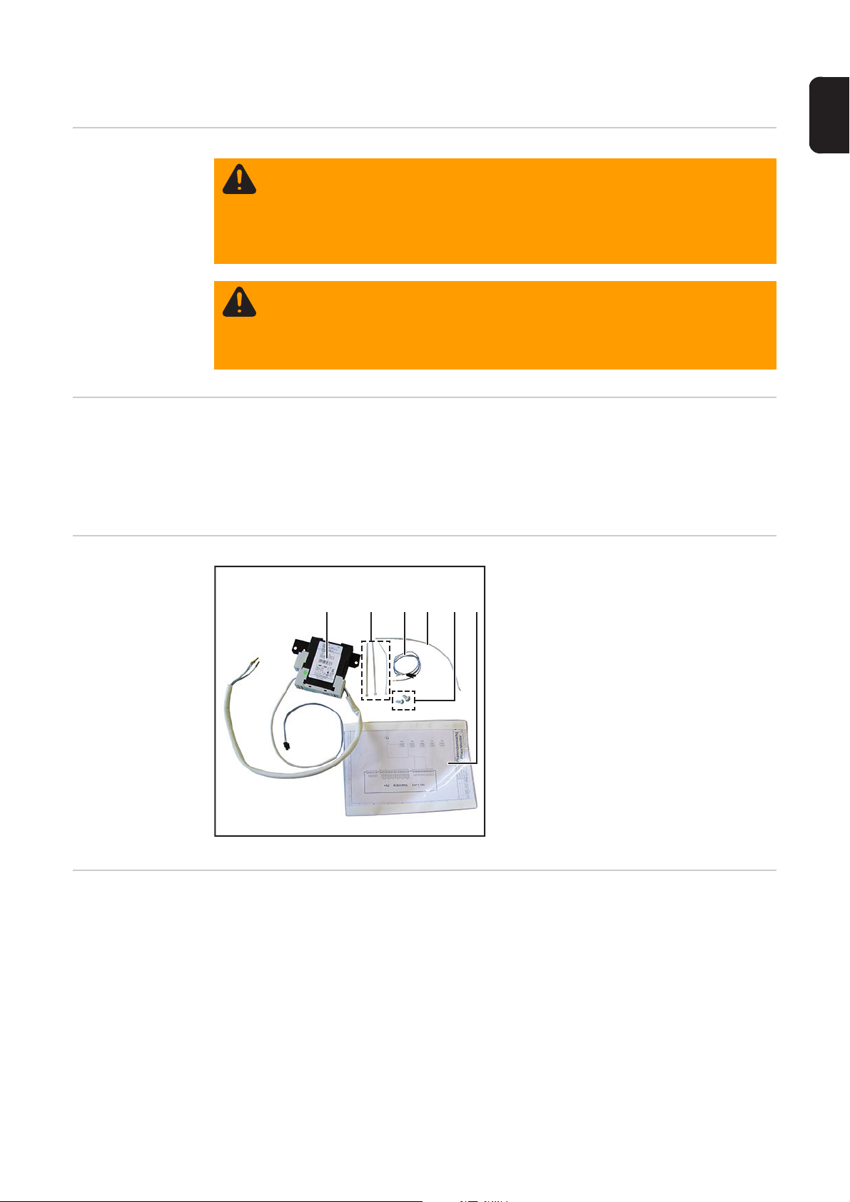
Lieferumfang (1) Phasenüberwachung
WARNUNG! Ein elektrischer Schlag kann tödlich sein. Vor Öffnen des Gerätes
- Netzschalter in Stellung - O - schalten
- Gerät vom Netz trennen
- ein verständliches Warnschild gegen Wiedereinschalten anbringen
- mit Hilfe eines geeigneten Messgerätes sicherstellen, dass elektrisch geladene Bauteile (z.B. Kondensatoren) entladen sind
WARNUNG! Fehlerhaft durchgeführte Arbeiten können schwerwiegende Personen- und Sachschäden verursachen. Nachfolgend beschriebene Tätigkeiten
dürfen nur von geschultem Fachpersonal durchgeführt werden! Beachten Sie das
Kapitel „Sicherheitsvorschriften“ in der Bedienungsanleitung der Stromquelle und
der Systemkomponenten.
(2) 3 x Kabelbinder
(1) (2) (3) (4) (5) (6)
(3) Kabel 2-polig mit Microfit-Stecker
(4) Kabel
(5) 2 x Schraube TX25
(6) Schaltplan
Erforderliches
Werkzeug
- Torx-Schraubendreher TX25
- Schlitz-Schraubendreher klein
- Seitenschneider
1

Einbau-Set Phasenüberwachung einbauen
1
Vorbereitung Stromquelle ausschalten und vom Netz trennen
Linken und rechten Seitenteil der Stromquelle entfernen
2
Hintere Abdeckung vom Roboter-Interface abmontieren
3
Roboter-Interface von der Stromquelle abmontieren
4
Einbau-Set Phasenüberwachung
einbauen
Phasenüberwachung gemäß Abbil-
1
dung hinten in die Stromquelle einsetzen
2
Phasenüberwachung mit 2 Schrauben
2
TX25 aus dem Lieferumfang montie-
1
2
ren
Kabel von der Phasenüberwachung
3
über den Netzfilter nach vorne verle-
3
3
gen
2

Kabellitzen gemäß Kabelaufdruck an
ROBIOREL
A2-X3
1
3
2
4
1
3
2
4
1
3
2
4
1
3
2
4
1
3
2
4
X3-1X3-2X3-3X3-4X3-5
123 7
814
456
910111213
(1)
(2)
(1)
5
8
7
9
7
4
der Blockklemme am Netzfilter-Ausgang dazuschließen
4
4
4
DE
Kabel 2-polig mit Microfit-Stecker (1) und Kabel (2) gemäß Schaltplan und Kabelaufdruck anschließen:
Kabel 2-polig mit Microfit-Stecker (1) an A2-X3/9 am Print ROBIREL und an X3-1/2
auf der Klemmleiste
Kabel (2) an A2-X3/2 am Print ROBIREL und an X3-2/2 auf der Klemmleiste
Kabel mit Kabelbinder fixieren
6
Kabel von der Phasenüberwachung
auf die rechte Stromquellen-Seite verlegen
Kabel von der Phasenüberwachung
8
durch die Durchführung führen
Roboter-Interface an der Stromquelle
9
montieren
3

Microfit-Stecker vom Kabel der Pha-
1
2
10
senüberwachung mit dem Microfit-Stecker des 2-poligen Kabels
zusammenstecken
10
10
Abschließende
Tätigkeiten
Hintere Abdeckung am Roboter-Interface montieren
Linken und rechten Seitenteil der Stromquelle montieren
4

General
Safety
Requirements The following components are required to install and use phase monitoring:
- the AB ProfiNet IRT FO robot interface (4,078,010) on the power source
- software configuration (4,062,016) on the robot interface
- Harting 6p torch cleaning device (4,100,695) on the robot interface
Scope of supply (1) Phase monitoring kit
WARNING! An electric shock can be fatal. Before opening the device
- Turn the mains switch to the "O" position
- Unplug the machine from the mains
- Put up an easy-to-understand warning sign to stop anybody inadvertently
switching it back on again
- Using a suitable measuring instrument, check to make sure that electrically
charged components (e.g. capacitors) have discharged
WARNING! Work that is carried out incorrectly can cause serious injury and damage. The following activities must only be carried out by trained and qualified personnel. Read the "Safety rules" chapter in the power source and system
components operating instructions.
(2) 3 x cable ties
(1) (2) (3) (4) (5) (6)
(3) Cable, 2-pin with Microfit connector
(4) Cable
(5) 2 x TX25 screws
(6) Circuit diagram
EN
Tools required - TX25 Torx screwdriver
- Small slotted screwdriver
- Diagonal cutting pliers
5

Installing the phase monitoring installation kit
1
Preparation Switch off the power source and disconnect it from the mains
Remove the left and right side panels from the power source
2
Take the rear cover off the robot interface
3
Disconnect the robot interface from the power source
4
Installing the
phase monitoring installation kit
Install the phase monitoring kit into the
1
rear of the power source as illustrated
Fit the phase monitoring kit using the
2
1
2
2
two TX25 screws provided
Route the cable from the phase moni-
3
toring kit to the front over the mains fil-
3
3
ter
6

Connect the cable strands as per the
ROBIOREL
A2-X3
1
3
2
4
1
3
2
4
1
3
2
4
1
3
2
4
1
3
2
4
X3-1X3-2X3-3X3-4X3-5
123 7
814
456
910111213
(1)
(2)
(1)
5
8
7
9
7
4
cable labelling to the block terminal on
the mains filter output
EN
4
4
4
Connect the 2-pin cable with the Microfit connector (1) and cable (2) according to the
circuit diagram and the cable labelling:
2-pin cable with Microfit connector (1) to A2-X3/9 on the ROBIREL PC board and to
X3-1/2 on the terminal strip
Cable (2) to A2-X3/2 on the ROBIREL PC board and to X3-2/2 on the terminal strip
Bind cables together with cable ties
6
Route the cable from the phase monitoring kit to the right-hand side of the
power source
Feed the cable from the phase monito-
8
ring kit through the bushing
Fit the robot interface to the power
9
source
7

10
1
2
10
And finally... Fit the rear cover of the robot interface
Fit the left and right side panels of the power source
Connect the Microfit connector on the
10
phase monitoring cable to the Microfit
connector on the 2-pin cable
8

EN
9

FRONIUS INTERNATIONAL GMBH
Froniusplatz 1, A-4600 Wels, Austria
Tel: +43 (0)7242 241-0, Fax: +43 (0)7242 241-3940
Under http://www.fronius.com/addresses you will find all addresses
of our Sales & service partners and Locations
E-Mail: sales@fronius.com
www.fronius.com
www.fronius.com/addresses
 Loading...