


Installation
Instructions
OPT/i WF TWIN R PushPull
DE
EN-US
Installationsanleitung
Installation instructions
42,0410,2753 001-27102022


Inhaltsverzeichnis
Allgemeines 4
Sicherheit 4
Lieferumfang 5
Erforderliche Werkzeuge 5
OPT/i WF TWIN R PushPull einbauen 6
Vorbereitung 6
OPT/i WF TWIN R PushPull einbauen 9
Abschließende Tätigkeiten 15
DE
3

Allgemeines
Sicherheit
WARNUNG!
Gefahr durch Fehlbedienung und fehlerhaft durchgeführte Arbeiten.
Schwere Personen- und Sachschäden können die Folge sein.
Alle in diesem Dokument beschriebenen Arbeiten und Funktionen dürfen
▶
nur von technisch geschultem Fachpersonal ausgeführt werden.
Dieses Dokument vollständig lesen und verstehen.
▶
Sämtliche Sicherheitsvorschriften und Benutzerdokumentationen dieses
▶
Gerätes und aller Systemkomponenten lesen und verstehen.
WARNUNG!
Gefahr durch elektrischen Strom.
Schwere Personen- und Sachschäden können die Folge sein.
Vor Beginn der Arbeiten alle beteiligten Geräte und Komponenten ausschal-
▶
ten und von Stromnetz trennen.
Alle beteiligten Geräte und Komponenten gegen Wiedereinschalten sichern.
▶
Nach dem Öffnen des Gerätes mit Hilfe eines geeigneten Messgerätes si-
▶
cherstellen, dass elektrisch geladene Bauteile (beispielsweise Kondensatoren) entladen sind.
WARNUNG!
Gefahr durch unzureichende Schutzleiter-Verbindungen.
Schwere Personen- und Sachschäden können die Folge sein.
Die Gehäuse-Schrauben stellen eine geeignete Schutzleiter-Verbindung für
▶
die Erdung des Gehäuses dar.
Die Gehäuse-Schrauben dürfen keinesfalls durch andere Schrauben ohne
▶
zuverlässige Schutzleiter-Verbindung ersetzt werden.
4

Lieferumfang
(1)
(2) (3) (4) (5) (6) (7)
DE
Erforderliche
Werkzeuge
(1) 2x Datenkabel 300 mm
(2) 2x Datenkabel 500 mm
(3) 12x Distanz M4 x 12 mm
(4) 8x Distanz M4 x 20 mm
(5) 8x Distanz M4 x 30 mm
(6) 2x Print PM63
(7) 2x Kabel weiß
Torx Schraubendreher TX 25
-
Schlitz-Schraubendreher 2 - 3 mm
-
Steckschlüssel SW 8 mm
-
Seitenschneider
-
ohne Abbildung:
8x Kabelbinder
-
diese Installationsanleitung
-
5

OPT/i WF TWIN R PushPull einbauen
4x8x
12 mm
20 mm 20 mm
30 mm 30 mm
2
2
2
3
2
3
4
4
4
4
4
4
4
4
5
8x TX25
Vorbereitung
Stromquellen ausschalten, vom Netz trennen und den TWIN-Drahtvorschub
1
von allen Systemkomponenten abschließen
Distanz 30 mm auf Distanz 20 mm aufschrauben (8x)
2
Distanz 12 mm auf Distanz 30 mm aufschrauben (4x)
3
6
4
5
8 Schrauben TX25 entfernen
Abdeckung entfernen

3x TX25
6
6
6
3 Schrauben TX25 entfernen
7x TX25
7
7
7
7
7
7
7
8
8
6
DE
7 Schrauben TX25 entfernen
7
Deckel und obere Abdeckung entfernen
8
7

9
9
9
9
10
10
4 Schrauben TX25 entfernen
12
11
9
Die Schweißbrenner-Anschlüsse nach vorne kippen
10
Mittels Schlitz-Schraubendreher die Verriegelungslasche des Datenkabels
11
500 mm nach oben drücken
Stecker-Gehäuse abziehen
12
Arbeitsschritte 11 und 12 für das zweite Datenkabel 500 mm wiederholen
13
8

OPT/i WF TWIN
1
1
2
R PushPull einbauen
Datenkabel 500 mm mit dem Winkelstecker voraus in den TWIN-Drahtvor-
1
schub einführen
Zweites Ende des Datenkabels am Schweißbrenner-Anschluss bis zum Ein-
2
rasten einstecken
Arbeitsschritte 1 und 2 für den unteren Schweißbrenner-Anschluss wieder-
3
holen
DE
9

5
4
4
5
5
5
WICHTIG! Beim Einsetzen der Schweißbrenner-Anschlüsse darauf achten, dass
6
6
6
6
Kabel nicht eingeklemmt, geknickt, abgeschert oder auf andere Weise
beschädigt werden.
Schweißbrenner-Anschlüsse einsetzen
4
Schweißbrenner-Anschlüsse mit 4 Schrauben TX25 fixieren
5
Anzugsmoment = 2,1 Nm
10
An den vorhandenen Gewindestiften mittels Steckschlüssel SW 8 mm die 4
6
Distanzenkombinationen 20 + 30 + 12 mm aufschrauben
Anzugsmoment = 0,5 Nm

8
8
8
8
8
8
8
8
7
7
7
7
7
7
7
7
An den beiden Prints mittels Steckschlüssel SW 8 mm die 4 Distanzen ent-
7
fernen
Anstelle der entfernten Distanzen die 8 Distanzenkombinationen 20 + 30 mm
8
aufschrauben
Anzugsmoment = 0,5 Nm
DE
11

9
10
12
11
1
2
9
2p
2p
4p
4p
10
11
2 Datenkabel 300 mm aus dem Lieferumfang jeweils am Print SR63 auf X9 /
9
PoE anstecken
2 Kabel weiß aus dem Lieferumfang gemäß Kabelaufdruck am Print SR63
anstecken:
Den 2p-Kabelstrang an X11 anstecken
10
Den 4p-Kabelstrang an X17 anstecken
11
Den dritten Kabelstrang durch die Durchführungen zur Geräte-Vorderseite
12
verlegen
12
13
14
14
14
14
Print PM63 einsetzen
8p
15
16
13
Print PM63 mittels Steckschlüssel SW 8 mm und mit 4 Distanzen M4 x 12
14
mm fixieren
Anzugsmoment = 0,5 Nm
DE
Den 8p-Kabelstrang am Print PM63 / X1 anstecken
15
Kabel von PoE am Print PM63 / X7 anstecken
16
13

17
18
Datenkabel 500 mm vom Schweißbrenner-Anschluss durch die
19
19
17
Durchführung führen ...
... und am Print PM63 / X9 PoE anstecken
18
14
Freies Kabel vom Schweißbrenner-Anschluss mit dem freien Kabelende zu-
19
sammenstecken
Arbeitsschritte 13 - 19 für den zweiten Print PM63 wiederholen
20

21
21
21
21
21
21
21
Kabel mit Kabelbinder fixieren, Kabelbinder ablängen
21
DE
Abschließende
Tätigkeiten
Obere Abdeckung und Deckel mit 10 Schrauben TX25 montieren
1
Anzugsmoment = 3 Nm
Abdeckung mit 8 Schrauben TX25 montieren
2
Anzugsmoment = 3 Nm
15

16

Table of contents
General 18
Safety 18
Scope of supply 19
Tools required 19
Installing the OPT/i WF TWIN R PushPull 20
Preparation 20
Installing the OPT/i WF TWIN R PushPull 23
Final tasks 29
EN-US
17

General
Safety
WARNING!
Danger from incorrect operation and work that is not carried out properly.
This can result in serious personal injury and damage to property.
All the work and functions described in this document must only be carried
▶
out by technically trained and qualified personnel.
Read and understand this document in full.
▶
Read and understand all safety rules and user documentation for this equip-
▶
ment and all system components.
WARNING!
Danger from electrical current.
This can result in serious personal injury and damage to property.
Before starting work, switch off all devices and components involved, and
▶
disconnect them from the grid.
Secure all devices and components involved so they cannot be switched back
▶
on.
After opening the device, use a suitable measuring instrument to check that
▶
electrically charged components (such as capacitors) have been discharged.
WARNING!
Danger due to insufficient ground conductor connection.
This can result in serious personal injury and damage to property.
The housing screws provide a suitable ground conductor connection for
▶
grounding the housing.
The housing screws must not under any circumstances be replaced by other
▶
screws without a reliable ground conductor connection.
18

Scope of supply
(1)
(2) (3) (4) (5) (6) (7)
EN-US
Tools required
(1) 2x data cable 300 mm
(2) 2x data cable 500 mm
(3) 12x spacer M4 x 12 mm
(4) 8x spacer M4 x 20 mm
(5) 8x spacer M4 x 30 mm
(6) 2x PC board PM63
(7) 2x cable white
TORX® screwdriver TX25
-
Slotted screwdriver 2-3 mm
-
Socket wrench 8 mm
-
Diagonal cutting pliers
-
Not shown:
8x cable ties
-
This set of Installation Instruc-
-
tions
19

Installing the OPT/i WF TWIN R PushPull
4x8x
12 mm
20 mm 20 mm
30 mm 30 mm
2
2
2
3
2
3
4
4
4
4
4
4
4
4
5
8x TX25
Preparation
Switch off power sources, disconnect from the grid, and isolate the TWIN
1
wirefeeder from all system components
Screw spacer 30 mm onto spacer 20 mm (8x)
2
Screw spacer 12 mm onto spacer 30 mm (4x)
3
20
4
5
Remove the eight TX25 screws
Remove the cover

3x TX25
6
6
6
Remove the three TX25 screws
7x TX25
7
7
7
7
7
7
7
8
8
6
EN-US
Remove the seven TX25 screws
7
Remove cover and top cover
8
21

9
9
9
9
10
10
Remove the four TX25 screws
12
11
9
Tilt the torch connectors forward
10
22
Using a slotted screwdriver, push the locking tab of the data cable 500 mm
11
upwards
Pull off connector housing
12
Repeat work steps 11 and 12 for the second data cable 500 mm
13

Installing the
1
1
2
OPT/i WF TWIN
R PushPull
Insert the data cable 500 mm into the TWIN wirefeeder with the angled con-
1
nector first
Insert the second end of the data cable into the torch connector until it
2
clicks into place
Repeat work steps 1 and 2 for the lower torch connector
3
EN-US
23

5
4
4
5
5
5
IMPORTANT! When inserting the torch connectors, ensure that the cables are
6
6
6
6
not kinked, pinched, cut, or otherwise damaged.
Insert torch connectors
4
Secure the torch connectors using four TX25 screws
5
Tightening torque = 2.1 Nm
24
Screw the four spacer combinations 20 + 30 + 12 mm onto the existing grub
6
screws using a socket wrench (8 mm)
Tightening torque = 0.5 Nm

8
8
8
8
8
8
8
8
7
7
7
7
7
7
7
7
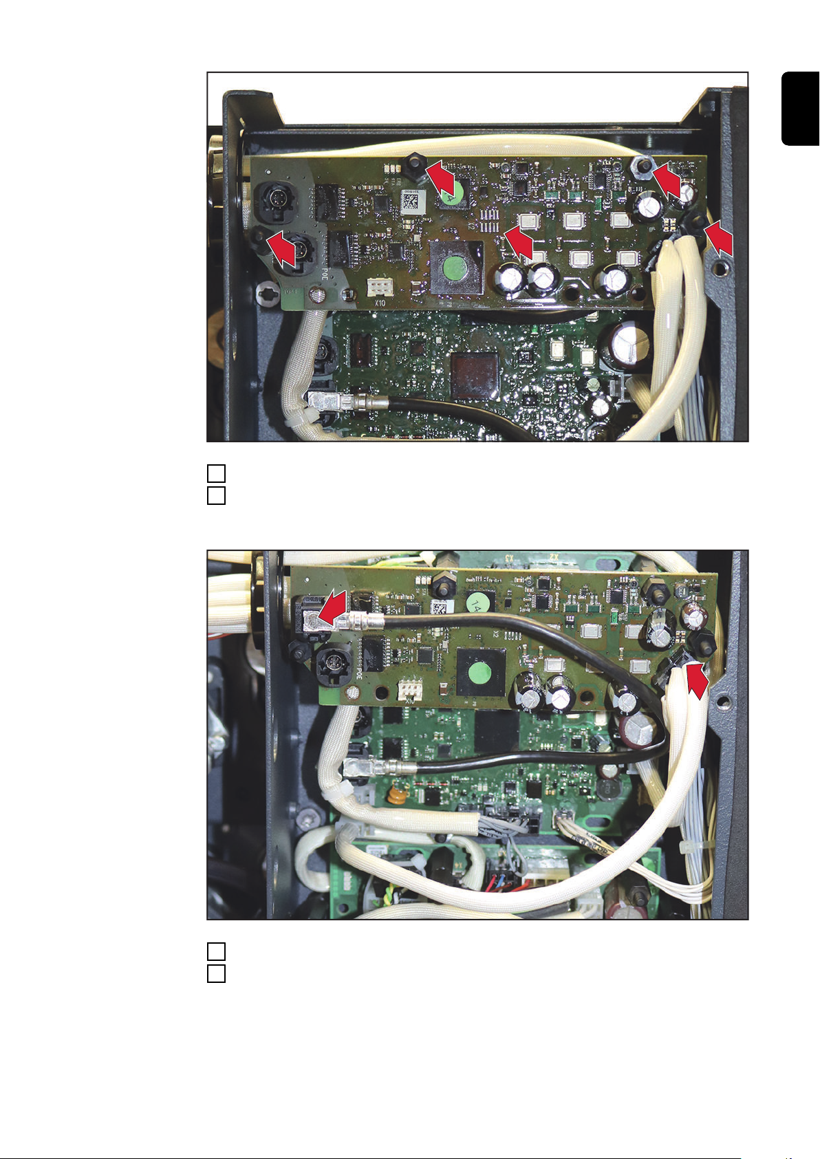
Remove the four spacers on the two PC boards using a socket wrench (8 mm)
7
Instead of the removed spacers, screw on the eight spacer combinations 20 +
8
30 mm
Tightening torque = 0.5 Nm
EN-US
25

9
10
12
11
1
2
9
2p
2p
4p
4p
10
11
Connect two data cables 300 mm from the scope of delivery to X9 / PoE on
9
PC board SR63
Connect two white cables from the scope of delivery to PC board SR63 according to the cable labeling:
Connect the 2p cable harness to X11
10
Connect the 4p cable harness to X17
11
Route the third cable harness through the bushings to the front of the device
12
26

13
14
14
14
14
Insert PC board PM63
8p
15
16
13
Fix PC board PM63 by means of a socket wrench (8 mm) and with four spa-
14
cers M4 x 12 mm
Tightening torque = 0.5 Nm
EN-US
Connect the 8p cable harness to PC board PM63/X1
15
Connect the cable from PoE to PC board PM63/X7
16
27
17
18
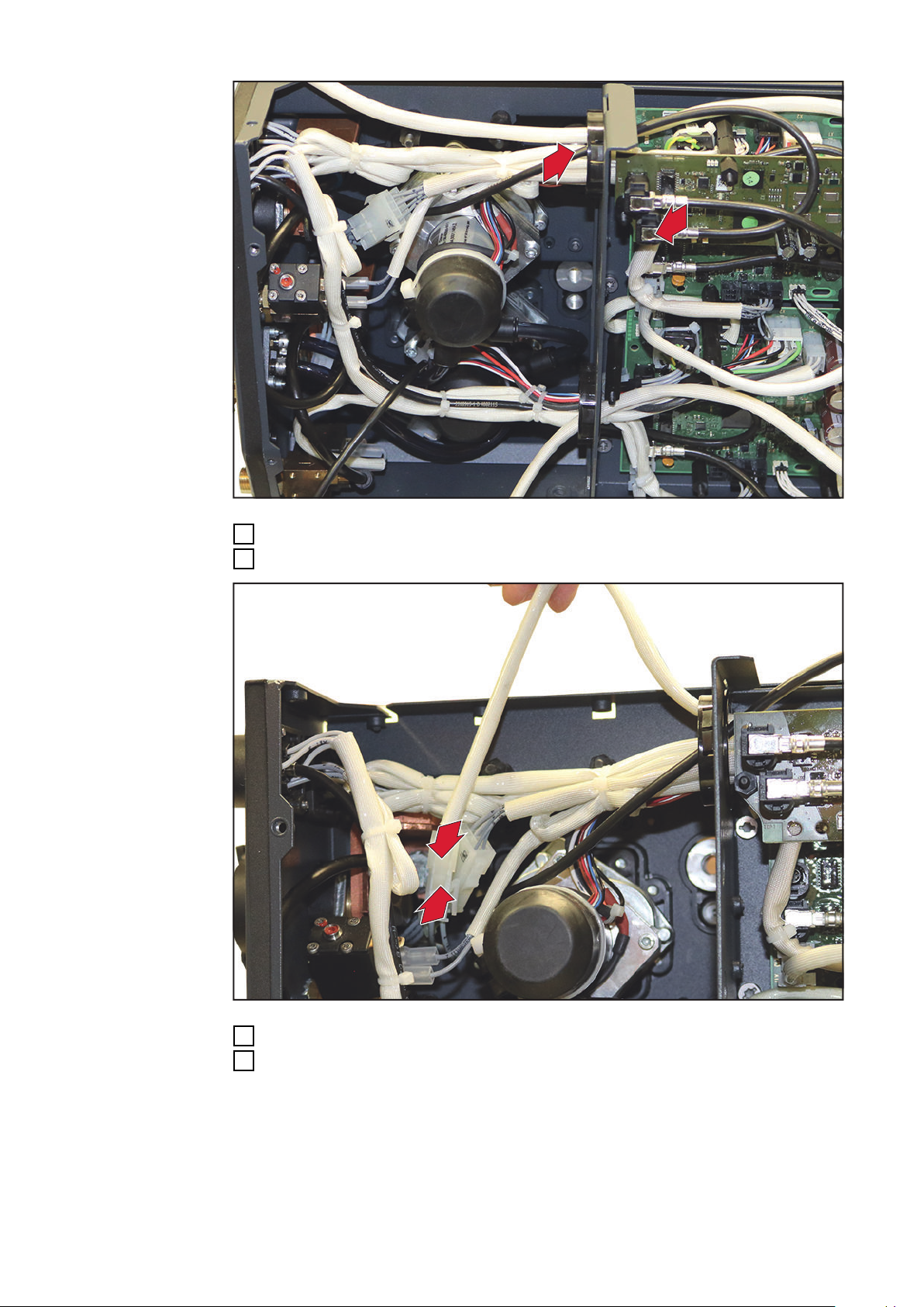
Feed the data cable 500 mm from the torch connector through the bushing...
19
19
17
... and connect to PC board PM63/X9 PoE
18
28
Connect the free cable from the torch connector to the free cable end
19
Repeat work steps 13 - 19 for the second PC board PM63
20

21
21
21
21
21
21
21
Attach cable using cable tie, cut cable tie to length
21
EN-US
Final tasks
Fit the top cover and cover with ten TX25 screws
1
Tightening torque = 3 Nm
Fit the cover with eight TX25 screws
2
Tightening torque = 3 Nm
29

30

EN-US
31

 Loading...