


/ Perfect Charging / Perfect Welding / Solar Energy
OPT/i WF Anschluss TMC
TIG Multi Connector OPT/i WF
connection
Installationsanleitung
DEEN-US
Systemerweiterung
Installation Instructions
System extension
42,0410,0015 001-12062018

2

Lieferumfang
Lieferumfang
DE
(2)
(1)
(1) OPT/i WF Anschluss TMC
(2) Kabelbaum
(3) Bedienpanel Gasprüfen und Drahteinfädeln
(4) 2 x Mutter M4
(5) 2 x Scheibe M4
(6) Kabelbinder
(7) dieses Dokument (nicht abgebildet)
(3)
(4)
(5)
(6)
3

OPT/i WF Anschluss TMC einbauen
Sicherheit
WARNUNG! Fehlbedienung und fehlerhaft durchgeführte Arbeiten können
schwerwiegende Personen- und Sachschäden verursachen.
Alle in diesem Dokument beschriebenen Arbeiten und Funktionen dürfen nur von
geschultem Fachpersonal ausgeführt werden, wenn folgende Dokumente vollständig gelesen und verstanden wurden:
- dieses Dokument
- sämtliche Bedienungsanleitungen der Systemkomponenten, insbesondere
Sicherheitsvorschriften
WARNUNG! Ein elektrischer Schlag kann tödlich sein. Vor Beginn der Arbeiten:
- Netzschalter der Stromquelle in Stellung - O - schalten
- Stromquelle vom Netz trennen
- sicherstellen, dass die Stromquelle bis zum Abschluss aller Arbeiten vom
Netz getrennt bleibt
Nach dem Öffnen des Gerätes mit Hilfe eines geeigneten Messgerätes sicherstellen, dass elektrisch geladene Bauteile (z.B. Kondensatoren) entladen sind.
VORSICHT! Verletzungsgefahr durch heiße Systemkomponenten. Vor Beginn
der Arbeiten alle heißen Systemkomponenten auf Zimmertemperatur (+25 °C,
+77 °F) abkühlen lassen, beispielsweise:
- Kühlmittel
- wassergekühlte Systemkomponenten
- Antriebsmotor des Drahtvorschubes
Vorbereitungen
(1) (2)
(1)
Sämtliche Verbindungen des Draht-
1
vorschubes von allen anderen Systemkomponenten trennen
Draht- oder Korbspule dem Drahtvor-
2
schub entnehmen
Drahtvorschub auf einer geeigneten
3
Unterlage ablegen
2 Schrauben TX 25 (1) lösen
4
Seitenteil rechts (2) entfernen
5
4
OPT/i WF Anschluss TMC einbauen
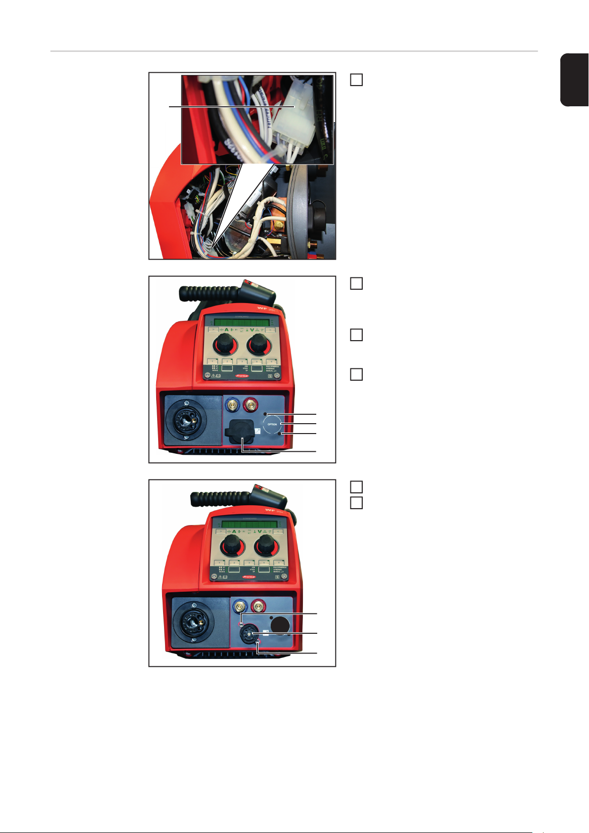
(1)
Stecker (1) voneinander trennen
1
- dies erleichtert die nachfolgenden
Arbeiten
Die Folie an der weißen Markierung (2)
2
aufschneiden, und den dahinter liegenden Kunststoff mit Hammer und einem
geeignetem Werkzeug ausbrechen
Die Folie an Position (3) und (4) auf-
3
schneiden, um die dahinter liegenden
Bohrungen freizulegen
Schutzabdeckung (5) entfernen
4
DE
(3)
(2)
(4)
(5)
(6)
(7)
(6)
2 Schrauben (6) TX20 lösen
5
Anschluss SpeedNet (7) entfernen
6
5

(6)
(7)
(6)
Anschluss SpeedNet (7) in die zuvor
7
freigelegte Öffnung einsetzen und mittels 2 Schrauben (6) TX20 festschrauben
- Anzugsmoment = 1,8 Nm
Schutzabdeckung (5) auf den An-
8
schluss SpeedNet (7) aufsetzen
den mitgelieferten OPT/i WF An-
9
schluss TMC in die Öffnung (8) einsetzen
(5)
(8)
OPT/i WF Anschluss TMC (9) mit Mut-
10
tern und Scheiben (10) festschrauben
(10)(10) (9)
6

(11)
(12)
Schutzabdeckung (11) auf OPT/i WF
11
Anschluss TMC aufsetzen
Abdeckung (12) öffnen
12
2 Schrauben TX20 (13) lösen
13
Je nach Geräteausführung bestehen-
14
des Bedienpanel Gasprüfen und
Drahteinfädeln mitsamt Kabelbaum
oder Blindabdeckung (14) entfernen
DE
(17) (16) (15)
(13)
(14)
(13)
Den Kabelbaum von OPT/i WF An-
15
schluss TMC (9) durch die Öffnung des
soeben entfernten Bedienpanels /
Blindabdeckung nach außen führen
Kabelbaum von OPT/i WF Anschluss
16
TMC (9) am mitgelieferten Bedienpanel Gasprüfen und Drahteinfädeln (15)
anschließen
- Anschluss X1 (16)
Zweiten Kabelbaum am Bedienpanel
17
Gasprüfen und Drahteinfädeln (15) anschließen
- Anschluss X4 (17)
7

(18)
(12)
(13)
(15)
(13)
Bedienpanel Gasprüfen und Drahtein-
18
fädeln (15) in den Drahtvorschub einsetzen und mittels 2 Schrauben TX20
(12) festschrauben
- Anzugsmoment = 1,8 Nm
Abdeckung (12) schließen
19
Das lose Ende des zweiten Kabelbau-
20
mes am Print SR63 im Drahtvorschub
anschließen
- Anschluss X4 (18)
Abschließende
Tätigkeiten
(1) (2)
(1)
Seitenteil (2) einsetzen
1
2 Schrauben 5 x 14 mm (1) mittels
2
Schraubendreher TX 25 festschrauben
- Anzugsmoment = 1,9 Nm
Drahtvorschub wieder in seine Aus-
3
gangsposition bringen
Draht- oder Korbspule einsetzen
4
Verbindungen mit anderen System-
5
komponenten wieder herstellen
8

Scope of Supply
Scope of Supply
EN-US
(2)
(1)
(1) TIG Multi Connector OPT/i WF connection
(2) Cable harness
(3) Gas test and wire threading control panel
(4) 2 x M4 nuts
(5) 2 x M4 washers
(6) Cable ties
(7) this document (not shown)
(3)
(4)
(5)
(6)
9

Installing TIG Multi Connector OPT/i WF connection
Safety
WARNING! Incorrect operation or shoddy workmanship can cause serious injury
or damage.
All functions described in this document may only be carried out by trained and
qualified personnel after they have fully read and understood the following documents:
- this document
- all the operating instructions for the system components, especially the safety rules
WARNING! An electric shock can be fatal. Before starting work:
- turn the power source mains switch to the "O" position
- disconnect the power source from the mains
- ensure that the power source remains disconnected from the mains until all
work has been completed
After opening the device, use a suitable measuring instrument to check that electrically charged components (e.g. capacitors) have been discharged.
CAUTION! Risk of scalding from hot system components. Before starting work allow all hot system components to cool down to room temperature (+25°C, +77°F),
for example:
- coolant
- water-cooled system components
- wirefeeder drive motor
Preparatory work
(1) (2)
(1)
Disconnect all connections on the wire-
1
feed unit from all other system components
Take wirespool or basket-type spool
2
off the wire-feed unit
Place the wire-feed unit on a suitable
3
base
Undo two TX 25 screws (1)
4
Remove the right side panel (2)
5
10

Installing TIG
Multi Connector
OPT/i WF connection
(1)
Disconnect connectors (1) from one
1
another
- this makes the subsequent tasks
easier
Cut the film along the white marking (2)
2
and break away the plastic behind it
using a hammer and a suitable tool
Cut the film at positions (3) and (4) to
3
expose the drill holes behind
Remove protective cover (5)
4
EN-US
(3)
(2)
(4)
(5)
(6)
(7)
(6)
Loosen the two TX20 screws (6)
5
Remove SpeedNet connector (7)
6
11

(6)
(7)
(6)
Insert SpeedNet connector (7) into the
7
previously exposed opening and fasten in place using two TX20 screws (6)
- Tightening torque = 1.8 Nm
Mount protective cover (5) on the
8
SpeedNet connector (7)
Insert the TIG Multi Connector OPT/i
9
WF connection supplied into the
opening (8)
(5)
(8)
Fasten TIG Multi Connector OPT/i WF
10
connection (9) using nuts and washers
(10)
(10)(10) (9)
12

(11)
(12)
Place protective cover (11) on the TIG
11
Multi Connector OPT/i WF connection
Open the cover (12)
12
Loosen the two TX20 screws (13)
13
Depending on the version of the appli-
14
ance, remove the gas test and wire
threading control panel including the
cable harness or dummy cover (14)
EN-US
(17) (16) (15)
(13)
(14)
(13)
Guide the TIG Multi Connector OPT/i
15
WF connection cable harness (9) out
through the control panel/dummy cover that has also been removed
Connect the TIG Multi Connector OPT/
16
i WF connection cable harness (9) to
the supplied gas test and wire threading control panel (15)
- X1 connection (16)
Connect second cable harness to the
17
gas test and wire threading control panel (15)
- X4 connection (17)
13

(18)
(12)
(13)
(15)
(13)
Insert the gas test and wire threading
18
control panel (15) into the wirefeeder
and fasten using two TX20 screws (12)
- Tightening torque = 1.8 Nm
Close the cover (12)
19
Connect the loose end of the second
20
cable harness to the SR63 PC board in
the wirefeeder
- X4 connection (18)
And finally...
(1) (2)
(1)
Fit the side panel (2)
1
Tighten two 5 x 14 mm screws (1)
2
using TX 25 screwdriver
- Tightening torque = 1.9 Nm
Return wire-feed unit to its original po-
3
sition
Insert wirespool or basket-type spool
4
Restore connections to other system
5
components
14

EN-US
15

FRONIUS INTERNATIONAL GMBH
Froniusplatz 1, A-4600 Wels, Austria
Tel: +43 (0)7242 241-0, Fax: +43 (0)7242 241-3940
E-Mail: sales@fronius.com
www.fronius.com
www.fronius.com/addresses
Under http://www.fronius.com/addresses you will find all addresses
of our Sales & service partners and Locations
 Loading...