


Installation
Instructions
OPT/i WF Sense Lead für SB 60i R
OPT/i WF Sense Lead for SB 60i R
DE
EN-US
Installationsanleitung
Installation instructions
42,0410,2748 001-07122022


Inhaltsverzeichnis
Sicherheit und Lieferumfang 4
Sicherheit 4
Lieferumfang OPT/i WF Sense Lead 4
OPT/i WF Sense Lead einbauen 5
Hinweis vor dem Einbau von OPT/i WF Sense Lead 5
Vorbereitung 5
OPT/i WF Sense Lead einbauen 6
Abschließende Tätigkeiten 11
DE
3

Sicherheit und Lieferumfang
(2)
(3)
(1)
Sicherheit
WARNUNG!
Gefahr durch Fehlbedienung und fehlerhaft durchgeführte Arbeiten.
Schwere Personen- und Sachschäden können die Folge sein.
Alle in diesem Dokument beschriebenen Arbeiten und Funktionen dürfen
▶
nur von technisch geschultem Fachpersonal ausgeführt werden.
Dieses Dokument vollständig lesen und verstehen.
▶
Sämtliche Sicherheitsvorschriften und Benutzerdokumentationen dieses
▶
Gerätes und aller Systemkomponenten lesen und verstehen.
WARNUNG!
Gefahr durch elektrischen Strom.
Schwere Personen- und Sachschäden können die Folge sein.
Vor Beginn der Arbeiten alle beteiligten Geräte und Komponenten ausschal-
▶
ten und vom Stromnetz trennen.
Alle beteiligten Geräte und Komponenten gegen Wiedereinschalten sichern.
▶
Nach dem Öffnen des Gerätes mit Hilfe eines geeigneten Messgerätes si-
▶
cherstellen, dass elektrisch geladene Bauteile (beispielsweise Kondensatoren) entladen sind.
WARNUNG!
Lieferumfang
OPT/i WF Sense
Lead
Gefahr durch heiße Systemkomponenten und / oder Betriebsmittel.
Schwere Verbrennungen und Verbrühungen können die Folge sein.
Vor Beginn der Arbeiten alle heißen Systemkomponenten und / oder Be-
▶
triebsmittel auf +25 °C / +77 °F abkühlen lassen (beispielsweise Kühlmittel,
wassergekühlte Systemkomponenten, Antriebsmotor des Drahtvorschubes, ...).
Geeignete Schutzausrüstung tragen (beispielsweise hitzebeständige Schutz-
▶
handschuhe, Schutzbrille, ...), wenn ein Abkühlen nicht möglich ist.
(1) 2 Schrauben TX20
(2) Sense Lead Stecker
(3) Schutzabdeckung
(4) Dieses Dokument (nicht abge-
bildet)
4

OPT/i WF Sense Lead einbauen
(1)
(1)(1) (1)
(1)(1)
(2) (1)
Hinweis vor dem
Einbau von OPT/i
WF Sense Lead
DE
Ist anstatt der Abdeckung (1) bereits eine Option im Gerät verbaut, kann OPT/i
WF Sense Lead nicht eingebaut werden.
Vorbereitung Der Einbau wird anhand einer rechten SB 60i R Geräteausführung beschrieben.
Der Einbau in eine linke SB 60i R Geräteausführung funktioniert auf die gleiche
Weise.
Sämtliche Verbindungen der SB 60i R von allen anderen Systemkomponen-
1
ten trennen
SB 60i R vom Roboter / der Balancerhalterung demontieren
2
SB 60i R auf einer ebenen und sauberen Unterlage mit der durchsichtigen
3
Abdeckung nach unten ablegen
6 Schrauben TX25 (1) lösen
4
Deckel (2) abnehmen
5
5

OPT/i WF Sense
(1)
(2)(3)
Lead einbauen
Die Abdeckung (1) entfernen
1
Die Schraube (2) entfernen
2
Die Schraube (2) = eine Sechskant-Schraube bei der rechten Gerätevari-
-
ante
Die Schraube (2) = eine Innensechskant-Schraube bei der linken Geräte-
-
variante
Das Stromkabel (3) nach oben klappen
3
6

TOP
Beim nachfolgenden Arbeitsschritt
(5)
(4)
(5)
TOP
4
sicherstellen, dass die Markierung
„TOP“ am Sense Lead Stecker
nach dem Einbau nach oben zeigt
DE
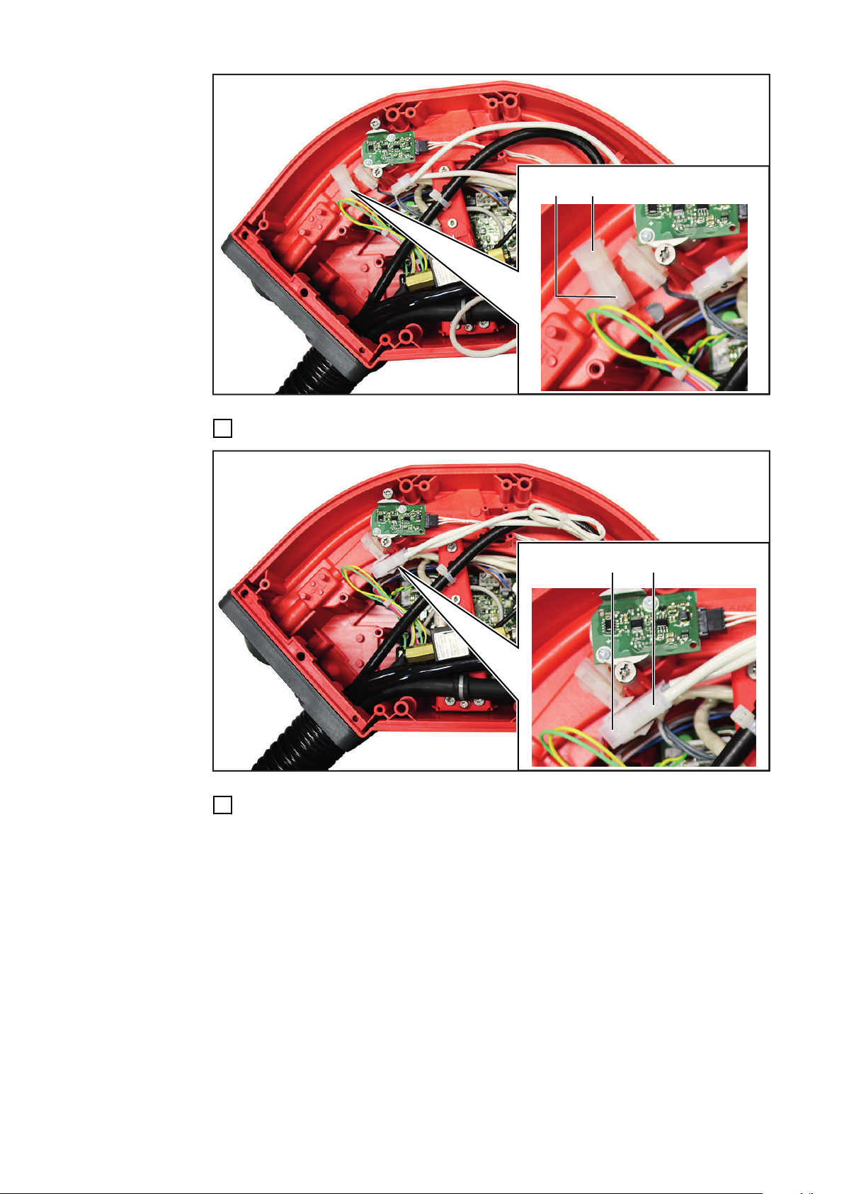
Den Sense Lead Stecker (4) in das Gerät einsetzen
5
die Markierung „TOP“ muss nach oben zeigen
-
Den Sense Lead Stecker mit den 2 Schrauben TX20 (5) festschrauben
6
Anzugsmoment 2 Nm (1.48 ft·lb)
-
7

(6)
(4)
Die Schutzabdeckung (6) über den Sense Lead Stecker (4) schieben
(6)
7
Die Schutzabdeckung (6) schließen
8
8

(2)
(9)
(8)
(7)
(9)
(8)
(7)
(2)
(10)
(10) (10)
(2)(3)
(10)
Das Stromkabel (3) wie dargestellt festschrauben:
(11) (7)
9
= Schraube (2)
1.
Sechskant-Schraube bei der rechten Gerätevariante
-
Innensechskant-Schraube bei der linken Gerätevariante
-
= Flachsteckzunge (7)
2.
= Tellerfeder (8) + (9)
3.
sicherstellen, dass die Tellerfedern wie dargestellt montiert werden
-
(siehe Detail)
= Kabelschuh (10) des Stromkabels (3)
4.
sicherstellen, dass der Kabelschuh (10) wie dargestellt montiert wird
-
(siehe Detail)
Anzugsmoment der Schraube (2) = 25 Nm (18.44 ft·lb)
-
DE
10
Das Kabel (11) vom Sense Lead Stecker an der Flachsteckzunge (7) anstecken
9
(12)(13)
Den Blindstecker (12) von der Buchse (13) abstecken
(13) (14)
11
Das Kabel (14) vom Sense Lead Stecker an der Buchse (13) anstecken
12
10

(15)
Die eingebauten Kabel mit dem Kabelbinder (15) fixieren
(1)(1) (1)
(1)(1)
(2) (1)
13
Die werksseitige Verlegung der Kabel in den Geräten kann variieren
-
In jedem Fall die neu hinzugefügten Kabel mit einem oder mehreren Ka-
-
belbindern so fixieren, dass diese Kabel nicht aus dem Gerät ragen und
nirgends scheuern
DE
Abschließende
Tätigkeiten
Den Deckel (2) in seine Originalposition bringen
1
Den Deckel (2) mit 6 Schrauben TX25 (1) festschrauben
2
Anzugsmoment 3 Nm (2.21 ft·lb)
-
SB 60i R in der ursprünglichen Position festschrauben
3
mit dem ursprünglichen Befestigungsmaterial (Schrauben, Scheiben, ....)
-
mit dem ursprünglichen Anzugsmoment
-
Verbindungen mit den anderen Systemkomponenten herstellen
4
11

12

Table of contents
Safety and scope of supply 14
Safety 14
OPT/i WF Sense Lead scope of supply 14
Installing the OPT/i WF Sense Lead 15
Note before installing OPT/i WF Sense Lead 15
Preparation 15
Installing the OPT/i WF Sense Lead 16
Final tasks 21
EN-US
13
Safety and scope of supply
(2)
(3)
(1)
Safety
WARNING!
Danger from incorrect operation and work that is not carried out properly.
This can result in serious personal injury and damage to property.
All the work and functions described in this document must only be carried
▶
out by technically trained and qualified personnel.
Read and understand this document in full.
▶
Read and understand all safety rules and user documentation for this equip-
▶
ment and all system components.
WARNING!
Danger from electrical current.
This can result in serious personal injury and damage to property.
Before starting work, switch off all the devices and components involved and
▶
disconnect them from the grid.
Secure all devices and components involved so they cannot be switched back
▶
on.
After opening the device, use a suitable measuring instrument to check that
▶
electrically charged components (such as capacitors) have been discharged.
WARNING!
OPT/i WF Sense
Lead scope of
supply
Danger due to hot system components and/or equipment.
This can result in serious burns or scalding.
Before starting work, allow all hot system components and/or equipment to
▶
cool to +25°C/+77°F (e.g., coolant, water-cooled system components, wirefeeder drive motor, etc.).
Wear suitable protective equipment (e.g., heat-resistant gloves, safety gog-
▶
gles, etc.) if cooling down is not possible.
(1) 2 TX20 screws
(2) Sense Lead plug
(3) Protective cover
(4) This document (not shown)
14

Installing the OPT/i WF Sense Lead
(1)
(1)(1) (1)
(1)(1)
(2) (1)
Note before installing OPT/i
WF Sense Lead
EN-US
If an option is already installed in the device instead of the cover (1), OPT/i WF
Sense Lead cannot be installed.
Preparation The installation is described with reference to a right-hand SB 60i R version of
the appliance. The installation in a left-hand SB 60i R version of the appliance
works in the same way.
Disconnect the SB 60i R from all other system components
1
Remove the SB 60i R from the robot / balancer bracket (loosen 4 x Allen
2
screws)
Place the SB 60i R on an even and clean surface with the transparent cover
3
facing down
Loosen the 6 TX25 screws (1)
4
Remove cover (2)
5
15

Installing the
(1)
(2)(3)
OPT/i WF Sense
Lead
Remove the cover (1)
1
16
Remove the screw (2)
2
The screw (2) = a hexagonal bolt on the right-hand version of the device
-
The screw (2) = an Allen screw on the left-hand version of the device
-
Fold the power cable (3) upwards
3

TOP
During the following step, make su-
(5)
(4)
(5)
TOP
4
re that the „TOP“ marking on the
Sense Lead plug points upwards
after installation
EN-US
Insert the Sense Lead plug (4) into the device
5
The „TOP“ marking must point upwards
-
Secure the Sense Lead plug with the 2 TX20 screws (5)
6
Tightening torque 2 Nm (1.48 ft lb)
-
17

(6)
(4)
Slide the protective cover (6) over the Sense Lead plug (4)
(6)
7
18
Close the protective cover (6)
8

(2)
(9)
(8)
(7)
(9)
(8)
(7)
(2)
(10)
(10) (10)
(2)(3)
(10)
Secure the power cable (3) as shown:
(11) (7)
9
= Screw (2)
1.
Hexagonal bolt on the right-hand version of the device
-
Allen screw on the left-hand version of the device
-
= Flat tab (7)
2.
= Disc springs (8) + (9)
3.
Ensure that the disc springs are fitted as shown (see detailed image)
-
= Cable lug (10) of the power cable (3)
4.
Ensure that the cable lug (10) is fitted as shown (see detailed image)
-
Tightening torque of the screw (2) = 25 Nm (18.44 ft·lb)
-
EN-US
10
Connect the cable (11) from the Sense Lead plug to the flat tab (7)
19

(12)(13)
Disconnect the dummy plug (12) from the socket (13)
(13) (14)
11
Connect the cable (14) from the Sense Lead plug to the socket (13)
12
20

(15)
Final tasks
(1)(1) (1)
(1)(1)
(2) (1)
Fix the installed cables with the cable tie (15)
13
The factory installation of the cables in the devices may vary
-
In any case, fix the newly added cables with one or more cable ties so
-
that these cables do not protrude from the device and do not chafe anywhere
EN-US
Place the cover (2) in its original position
1
Secure the cover (2) using 6 TX25 screws (1)
2
Tightening torque 3 Nm (2.21 ft lb)
-
Secure the SB 60i R in the original position
3
with the original fastening material (screws, washers, etc.)
-
with the original tightening torque
-
Establish the connections to the other system components
4
21

22

EN-US
23

Fronius International GmbH
Froniusstraße 1
4643 Pettenbach
Austria
contact@fronius.com
www.fronius.com
Under www.fronius.com/contact you will find the adresses
of all Fronius Sales & Service Partners and locations.
spareparts.fronius.com
SPAREPARTS
ONLINE
 Loading...