


/ Perfect Charging / Perfect Welding / Solar Energy
OPT/i WF R Drahtspulen-Aufnahme
Drahtende
OPT/i WF R wirespool holder wire
end sensor
Einbauanleitung
Ersatzteilliste
DEEN
Systemerweiterung
Fitting instructions
Spare parts list
System extension
42,0410,2087 002-09092016

2

Inhaltsverzeichnis
Allgemeines ............................................................................................................................................... 5
Funktionsprinzip.................................................................................................................................... 5
Voraussetzungen.................................................................................................................................. 5
Lieferumfang......................................................................................................................................... 5
Aufbau der Bremse............................................................................................................................... 5
Sicherheit.............................................................................................................................................. 6
OPT/i WF R Drahtspulen-Aufnahme Drahtende montieren....................................................................... 7
OPT/i WF R Drahtspulen-Aufnahme Drahtende montieren.................................................................. 7
Sensor anschließen .............................................................................................................................. 8
Wartung ..................................................................................................................................................... 9
Korrekte Einstellung des Sensors überprüfen ..................................................................................... 9
Sensor einstellen .................................................................................................................................. 9
Verschleißteile wechseln ...................................................................................................................... 10
Appendix 21
Spare parts list: OPT/i WF R Drahtspulen-Aufnahme Drahtende.............................................................. 22
DE
3

4

Allgemeines
Funktionsprinzip OPT/i WF R Drahtspulen-Aufnahme Drahtende tastet die Drahtspule permanent ab. Wird
die letzte Lage der Drahtelektrode abgespult, registriert der eingebaute Sensor dies und
gibt einen Drahtende-Alarm aus - der Schweißprozess wird durch den Drahtende-Alarm
jedoch nicht unterbrochen.
DE
Voraussetzungen
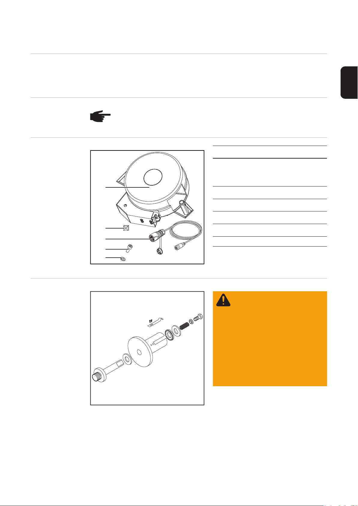
Lieferumfang (1) Drahtspulen-Aufnahme
HINWEIS! OPT/i WF R Drahtspulen-Aufnahme Drahtende kann nur verwendet
werden, wenn OPT/i Ext. Sensorstecker in dem verwendeten Drahtvorschub / der
verwendeten SplitBox eingebaut ist.
(2) Kabelöse
zur Fixierung des Verbindungskabels Kabels mittels Kabelbinder an
(1)
(2)
(3)
(4)
(5)
(3) Verbindungskabel
(4) 4 Innensechskant-Schrauben
(5) 4 Sicherungsringe
(6) 5 Kabelbinder (nicht abgebildet)
(7) dieses Dokument (nicht abgebil-
einer beliebigen Position
M10 x 16 mm
det)
Aufbau der Bremse
WARNUNG! Fehlerhafte Monta-
ge kann schwerwiegende Personen- und Sachschäden
verursachen.
- Bremse nicht zerlegen.
- Wartungs- und Servicearbeiten an der Bremse nur von
geschultem Fachpersonal
durchführen lassen.
Die Bremse ist nur komplett verfügbar.
Nebenstehende Abbildung dient
nur zur Information!
5

Sicherheit
WARNUNG! Fehlbedienung und fehlerhaft durchgeführte Arbeiten können
schwerwiegende Personen- und Sachschäden verursachen.
Alle in diesem Dokument beschriebenen Arbeiten und Funktionen dürfen nur von
geschultem Fachpersonal ausgeführt werden, wenn folgende Dokumente vollständig gelesen und verstanden wurden:
- dieses Dokument
- sämtliche Bedienungsanleitungen der Systemkomponenten, insbesondere
Sicherheitsvorschriften
WARNUNG! Ein elektrischer Schlag kann tödlich sein. Vor Beginn der Arbeiten:
- Netzschalter der Stromquelle in Stellung - O - schalten
- Stromquelle vom Netz trennen
- sicherstellen, dass die Stromquelle bis zum Abschluss aller Arbeiten vom
Netz getrennt bleibt
Nach dem Öffnen des Gerätes mit Hilfe eines geeigneten Messgerätes sicherstellen, dass elektrisch geladene Bauteile (z.B. Kondensatoren) entladen sind.
VORSICHT! Verletzungsgefahr durch austretende Drahtelektrode. Ist ein Abspul-Drahtvorschub im Schweißsystem vorhanden, vor Beginn der Arbeiten:
- Netzschalter des Abspul-Drahtvorschubes in Stellung - O - schalten
- Abspul-Drahtvorschub vom Netz trennen
- sicherstellen, dass der Abspul-Drahtvorschub bis zum Abschluss aller Arbeiten vom Netz getrennt bleibt
VORSICHT! Verletzungsgefahr durch heiße Systemkomponenten. Vor Beginn
der Arbeiten alle heißen Systemkomponenten auf Zimmertemperatur (+25 °C,
+77 °F) abkühlen lassen, beispielsweise:
- Kühlmittel
- wassergekühlte Systemkomponenten
- Antriebsmotor des Drahtvorschubes
6

OPT/i WF R Drahtspulen-Aufnahme Drahtende montieren
OPT/i WF R
Drahtspulen-Aufnahme Drahtende
montieren
Drahtspulen-Aufnahme an einer ebe-
1
nen, sauberen und glatten Montagefläche mittels mitgelieferten Schrauben
und Sicherungsringen festschrauben
Drahtspulen-Abdeckung (1) öffnen
2
DE
(2)
(1)
Haltearm (2) inklusive Sensoreinheit
3
nach außen Drücken und dadurch arretieren
Drahtspule / Korbspule mit Adapter in
4
die Drahtspulen-Aufnahme einsetzen
7

Arretierung des Haltearms (2) durch
5
drücken auf die Entriegelung (3) lösen
und sicherstellen, dass der Gleitschuh
an der Drahtelektrode anliegt
HINWEIS! Der Haltearm (2) darf
die Drahtspule und die Drahtelektrode nicht berühren.
(3)
Drahtförder-Schlauch zwischen Drahtspulen-Aufnahme und Drahtvorschub montie-
6
ren
Drahtelektrode einlaufen lassen
7
Drahtspulen-Abdeckung (1) schließen
8
Sensor anschließen
HINWEIS! Der Drahtvorschub / die SplitBox erkennt den angesteckten Sensor
am Verbindungskabel! Daher für jeden Sensor nur das mitgelieferte Verbindungskabel verwenden - das Verbindungskabel des Sensors ist mit der Artikelnummer und Bezeichnung des Sensors markiert.
(3)(1) (2)
1
(4)
Stecker (4) mit dem Stecker des Sensors der Drahtspulen-Aufnahme Drahtende ver-
2
binden
Falls notwendig, die Kabel mittels Kabelbinder und Kabelöse fixieren
3
HINWEIS! Den Stecker (1) des
Verbindungskabels nur an Sensoranschlüsse (2) mit einer roten
Codierung (3) anschließen.
Stecker (1) vom Verbindungskabel an
einen Anschluss OPT/i Ext. Sensorstecker (2) des Drahtvorschubes / der
SplitBox anschließen
8

Wartung
DE
Korrekte Einstellung des Sensors
überprüfen
HINWEIS! Nachfolgende Einstel-
lung des Sensors bei jedem 25.
Drahtspulen-Wechsel kontrollieren. Gleitschuh und Sensor gegebenenfalls nachjustieren oder
austauschen.
(1)
(2)
0,5 mm (0.02 in.)
Ist der gemessene Abstand kleiner als 0,5 mm (0.02 in.):
Abstand ist zu klein - Gleitschuh und Sensor gemäß nachfolgendem Abschnitt einstel-
3
len
Ist der gemessene Abstand größer als 0,5 mm (0.02 in.):
Abstand ist groß genug - Arretierung des Haltearms lösen und sicherstellen, dass der
3
Gleitschuh an der Drahtelektrode anliegt
Haltearm inklusive Sensoreinheit von
1
der Drahtspule abheben und arretieren
Mittels Messschieber den Abstand zwi-
2
schen der Gleitfläche des Gleitschuhs
(1) und Oberfläche des Sensors (2)
messen
Sensor einstellen
(5)
(5)
HINWEIS! Der Haltearm darf die Drahtspule und die Drahtelektrode nicht berühren.
HINWEIS! Ist ein Einstellen im
(1)(2)(3)(4)
1
2
3
nachfolgend beschriebenen Ausmaß nicht mehr möglich, den
Gleitschuh (1) austauschen.
Haltearm (3) inklusive Sensoreinheit
von der Drahtspule abheben und arretieren
Schrauben (5) lösen und Gleitschuh
(1) mit Sensor (2) vom Haltearm (3) abnehmen
Mutter (4) lösen
HINWEIS! Beim Ab- und Aufschrauben des Gleitschuhes (1)
auf den Sensor (2) darauf achten,
dass das Kabel des Sensors nicht
verdrillt wird.
9
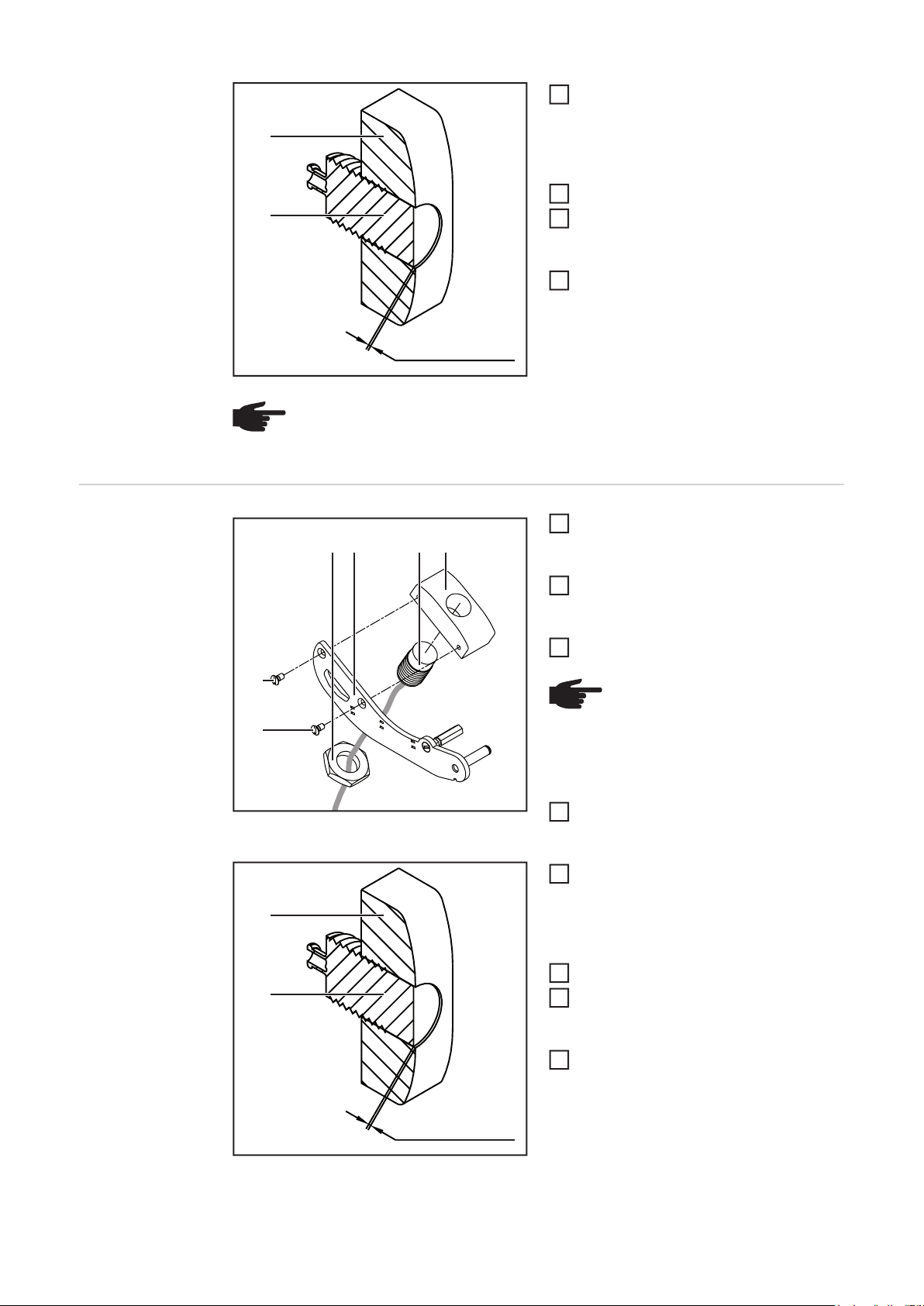
Gleitschuh (1) vom Sensor (2) ab-
4
schrauben, so dass der Abstand zwi-
(1)
(2)
2 mm (0.079 in.)
HINWEIS! Der Haltearm (3) darf die Drahtspule und die Drahtelektrode nicht berühren.
schen Gleitfläche des Gleitschuhs und
Oberfläche des Sensors 2 mm (0.079
in.) beträgt
Mutter (4) festschrauben
5
Gleitschuh (1) mit Sensor (2) auf dem
6
Haltearm (3) positionieren und mittels
2 Schrauben (5) festschrauben
Arretierung des Haltearms (3) lösen
7
und sicherstellen, dass der Gleitschuh
an der Drahtelektrode anliegt
Verschleißteile
wechseln
(5)
(5)
(1)
(2)
Haltearm (3) inklusive Sensoreinheit
1
(1)(2)(3)(4)
von der Drahtspule abheben und arretieren
Schrauben (5) lösen und Gleitschuh
2
(1) mit Sensor (2) vom Haltearm (3) abnehmen
Seckskantmutter (4) lösen
3
HINWEIS! Beim Ab- und Aufschrauben des Gleitschuhes (1)
auf den Sensor (2) darauf achten,
dass das Kabel des Sensors nicht
verdrillt wird.
Gleitschuh (1) vom Sensor (2) ab-
4
schrauben
Neuen Gleitschuh (1) auf den Sensor
5
(2) aufschrauben, so dass der Abstand
zwischen Gleitfläche des Gleitschuhs
und Oberfläche des Sensors 2 mm
(0.079 in.) beträgt
Seckskantmutter (4) festschrauben
6
Gleitschuh (1) mit Sensor (2) auf dem
7
Haltearm positionieren und mittels 2
Schrauben (5) festschrauben
Arretierung des Haltearms (3) lösen
8
und sicherstellen, dass der Gleitschuh
(1) an der Drahtelektrode anliegt
10
2 mm (0.079 in.)

HINWEIS! Der Haltearm (3) darf die Drahtspule und die Drahtelektrode nicht berühren.
DE
11

12

Contents
General ...................................................................................................................................................... 15
Functional principle............................................................................................................................... 15
Prerequisites......................................................................................................................................... 15
Scope of supply .................................................................................................................................... 15
Design of the brake............................................................................................................................... 15
Safety.................................................................................................................................................... 16
Fitting the OPT/i WF R wirespool holder wire end sensor ......................................................................... 17
Fitting the OPT/i WF R wirespool holder wire end sensor .................................................................... 17
Connecting the sensor.......................................................................................................................... 18
Maintenance .............................................................................................................................................. 19
Checking that the sensor has been adjusted correctly ........................................................................ 19
Adjusting the sensor ............................................................................................................................. 19
Replacing wearing parts ....................................................................................................................... 20
Appendix 21
Spare parts list: OPT/i WF R Drahtspulen-Aufnahme Drahtende.............................................................. 22
EN
13

14
General
Functional principle
Prerequisites
Scope of supply (1) Wirespool holder
The OPT/i WF R wirespool holder wire end sensor constantly monitors the wirespool. Its
integrated sensor detects when the final layer of the wire electrode has been wound off and
outputs a wire end alarm. This alarm does not interrupt the welding process.
NOTE! The OPT/i WF R wirespool holder wire end sensor can only be used if an
OPT/i ext. sensor plug has been installed in the respective wirefeeder or SplitBox.
(2) Cable eyelet
For attaching the connecting cable
as required using cable ties
(1)
(2)
(3)
(4)
(5)
(3) Connecting cable
(4) 4x M10 x 16 mm Allen screws
(5) 4x locking rings
(6) 5x cable ties (not shown)
(7) This document (not shown)
EN
Design of the
brake
WARNING! Fitting the equipment
incorrectly can cause serious injury and damage.
- Do not dismantle the brake.
- Maintenance and servicing of
brakes is to be carried out by
trained, qualified personnel
only.
The brake is only available as a
complete unit.
This illustration is for information
purposes only.
15

Safety
WARNING! Incorrect operation or shoddy workmanship can cause serious injury
or damage.
All functions described in this document may only be carried out by trained and
qualified personnel after they have fully read and understood the following documents:
- this document
- all the operating instructions for the system components, especially the safety rules
WARNING! An electric shock can be fatal. Before starting work:
- turn the power source mains switch to the "O" position
- disconnect the power source from the mains
- ensure that the power source remains disconnected from the mains until all
work has been completed
After opening the device, use a suitable measuring instrument to check that electrically charged components (e.g. capacitors) have been discharged.
CAUTION! Risk of injury from wire electrode emerging at speed. If the welding
system contains an unreeling wirefeeder, also carry out the following actions before starting work:
- turn the mains switch of the unreeling wirefeeder to the "O" position
- disconnect the unreeling wirefeeder from the mains
- ensure that the unreeling wirefeeder remains disconnected from the mains
until all work has been completed
CAUTION! Risk of scalding from hot system components. Before starting work,
allow all hot system components to cool down to room temperature (+25°C,
+77°F). For example:
- coolant
- water-cooled system components
- wirefeeder drive motor
16

Fitting the OPT/i WF R wirespool holder wire end
sensor
Fitting the OPT/i
WF R wirespool
holder wire end
sensor
Screw the wirespool holder to a flat,
1
clean and smooth surface using the
supplied screws and locking rings
Open the wirespool cover (1)
2
EN
(2)
(1)
Push out the retaining arm (2) and sen-
3
sor unit to lock in place
Insert the wirespool/basket-type spool
4
and adapter into the wirespool holder
17

Unlock the retaining arm (2) by pres-
5
sing on the catch (3) and ensure that
the shoe is touching the wire electrode
NOTE! The retaining arm (2) must
not touch the wirespool or the wire
electrode.
(3)
Fit the wirefeeding hose between the wirespool holder and the wirefeeder
6
Feed in the wire electrode
7
Close the wirespool cover (1)
8
Connecting the
sensor
NOTE! The wirefeeder/SplitBox recognises that there is a sensor connected to
the connecting cable. Each sensor is supplied with its own connecting cable,
which must be used. The sensor connecting cable will be marked with the item
number and name of sensor.
(3)(1) (2)
1
(4)
Connect plug (4) to the sensor plug of the wirespool holder wire end sensor
2
If necessary, secure the cable with cable ties and cable eyelets
3
NOTE! The plug (1) of the connecting cable may only be connected to the sensor connections
(2) that are colour-coded red (3).
Connect the plug (1) on the connecting
cable to an OPT/i ext. sensor plug (2)
connection of the wirefeeder/SplitBox
18

Maintenance
Checking that the
sensor has been
adjusted correctly
NOTE! Check the following sen-
sor setting after every 25th wirespool change. Adjust or replace
shoe and sensor as required.
Lift the retaining arm and sensor unit
1
(1)
(2)
0,5 mm (0.02 in.)
If the measured distance is less than 0.5 mm (0.02 in):
The gap is too small – adjust the shoe and sensor as described in the following section
3
If the measured distance is greater than 0.5 mm (0.02 in):
The gap is large enough - undo the retaining arm lock and ensure that the shoe is
3
touching the wire electrode
off the wirespool and lock in place
Using a calliper, measure the distance
2
between the sliding surface of the shoe
(1) and the surface of the sensor (2)
EN
Adjusting the
sensor
(5)
(5)
NOTE! The retaining arm must not touch the wirespool or the wire electrode.
NOTE! If adjustment as described
(1)(2)(3)(4)
1
2
3
below is no longer possible, replace the shoe (1).
Lift the retaining arm (3) and sensor
unit off the wirespool and lock in place
Undo screws (5) and take the shoe (1)
and sensor (2) off the retaining arm (3)
Undo nut (4)
NOTE! When screwing or unscrewing the shoe (1) to/from the
sensor (2), ensure that the sensor
cable is not twisted.
19

Unscrew the shoe (1) from the sensor
4
(2), ensuring that the gap between the
(1)
(2)
2 mm (0.079 in.)
NOTE! The retaining arm (3) must not touch the wirespool or the wire electrode.
sliding surface of the shoe and the surface of the sensor is 2 mm (0.079 in.)
Tighten nut (4)
5
Position the shoe (1) and sensor (2) on
6
the retaining arm (3) and tighten using
two screws (5)
Unlock the retaining arm (3) and ensu-
7
re that the shoe is touching the wire
electrode
Replacing wearing parts
(5)
(5)
(1)
(2)
Lift the retaining arm (3) and sensor
1
(1)(2)(3)(4)
unit off the wirespool and lock in place
Undo screws (5) and take the shoe (1)
2
and sensor (2) off the retaining arm (3)
Undo the hexagonal nut (4)
3
NOTE! When screwing or unscrewing the shoe (1) to/from the
sensor (2), ensure that the sensor
cable is not twisted.
Unscrew the shoe (1) from the sensor
4
(2)
Screw a new shoe (1) onto the sensor
5
(2), ensuring that the gap between the
sliding surface of the shoe and the surface of the sensor is 2 mm (0.079 in.)
Tighten the hexagonal nut (4)
6
Position the shoe (1) and sensor (2) on
7
the retaining arm and tighten using two
screws (5)
Unlock the retaining arm (3) and ensu-
8
re that the shoe (1) is touching the wire
electrode
20
2 mm (0.079 in.)
NOTE! The retaining arm (3) must not touch the wirespool or the wire electrode.

Appendix
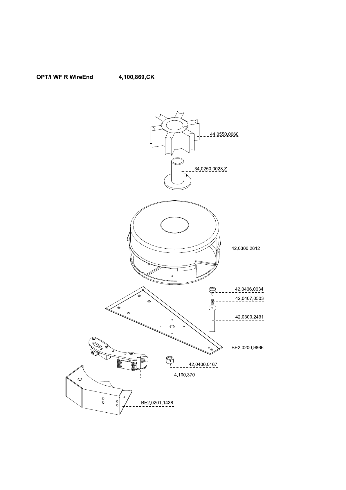
Spare parts list: OPT/i WF R Drahtspulen-Aufnahme
Drahtende
22

23

FRONIUS INTERNATIONAL GMBH
Froniusplatz 1, A-4600 Wels, Austria
Tel: +43 (0)7242 241-0, Fax: +43 (0)7242 241-3940
E-Mail: sales@fronius.com
www.fronius.com
www.fronius.com/addresses
Under http://www.fronius.com/addresses you will find all addresses
of our Sales & service partners and Locations
 Loading...