


Fronius prints on elemental chlorine free paper (ECF) sourced from certified sustainable forests (FSC).
/ Perfect Charging / Perfect Welding / Solar Energy
OPT/i WF R Drahtende-Ringsensor
OPT/i WF R wire end ring sensor
Czujnik pierścieniowy końca drutu
OPT/i WF R
Installationsanleitung
Ersatzteilliste
DEENPL
Systemerweiterung
Installations instructions
Spare parts list
System extension
Instrukcji instalacji
Lista części zamiennych
Rozbudowa systemu
42,0410,2088 004-24092019

2

Inhaltsverzeichnis
Allgemeines ............................................................................................................................................... 5
Lieferumfang......................................................................................................................................... 5
Voraussetzungen.................................................................................................................................. 5
Anschlussbelegungen........................................................................................................................... 5
OPT/i WF R Drahtende-Ringsensor montieren ......................................................................................... 7
Sicherheit.............................................................................................................................................. 7
Sensor auf ein Drahtfass montieren ..................................................................................................... 8
Sensor auf eine Großspule montieren.................................................................................................. 9
Sensor auf die Drahtfass-Aufnahme WF MOUNTING Drum montieren.............................................. 10
Sensor anschließen .............................................................................................................................. 11
OPT/i WF R Drahtende-Ringsensor einstellen .....................................................................................11
Funktionsweise des Schalters "Delay" ................................................................................................. 12
Appendix 33
Spare parts list: OPT/i WF R Drahtende-Ringsensor ................................................................................ 34
DE
3

4

Allgemeines
Lieferumfang (1) Sensor mit Halterung
(2) Verbindungskabel
DE
Voraussetzungen
(1)
(1)
HINWEIS!
OPT/i WF R Drahtende-Ringsensor kann nur verwendet werden, wenn OPT/i Ext.
Sensorstecker in dem verwendeten Drahtvorschub / der verwendeten SplitBox eingebaut ist.
(3) dieses Dokument (nicht abgebil-
det)
Anschlussbelegungen
Anschlussbelegung des Steckers vom Verbindungskabel:
1. BN (braun)
2. nicht verwendet
3. BU (blau)
4. BK (schwarz)
3.
2.
4.
1.
5

Anschlussbelegung des Sensors:
1.
3.
4.
1. BN (braun)
4.. BU (blau)
4. BK (schwarz)
6

OPT/i WF R Drahtende-Ringsensor montieren
DE
Sicherheit
WARNUNG!
Fehlbedienung und fehlerhaft durchgeführte Arbeiten können schwerwiegende Personen- und Sachschäden verursachen.
Alle in diesem Dokument beschriebenen Arbeiten und Funktionen dürfen nur von geschultem Fachpersonal ausgeführt werden, wenn folgende Dokumente vollständig gelesen und
verstanden wurden:
► dieses Dokument
► sämtliche Bedienungsanleitungen der Systemkomponenten, insbesondere Sicher-
heitsvorschriften
WARNUNG!
Ein elektrischer Schlag kann tödlich sein.
Vor Beginn der Arbeiten:
► Netzschalter der Stromquelle in Stellung - O - schalten
► Stromquelle vom Netz trennen
► sicherstellen, dass die Stromquelle bis zum Abschluss aller Arbeiten vom Netz ge-
trennt bleibt
Nach dem Öffnen des Gerätes mit Hilfe eines geeigneten Messgerätes sicherstellen, dass
elektrisch geladene Bauteile (z.B. Kondensatoren) entladen sind.
VORSICHT!
Verletzungsgefahr durch austretende Drahtelektrode.
Ist ein Abspul-Drahtvorschub im Schweißsystem vorhanden, vor Beginn der Arbeiten:
► Netzschalter des Abspul-Drahtvorschubes in Stellung - O - schalten
► Abspul-Drahtvorschub vom Netz trennen
► sicherstellen, dass der Abspul-Drahtvorschub bis zum Abschluss aller Arbeiten vom
Netz getrennt bleibt
VORSICHT!
Verletzungsgefahr durch heiße Systemkomponenten.
Vor Beginn der Arbeiten alle heißen Systemkomponenten auf Zimmertemperatur (+25 °C,
+77 °F) abkühlen lassen, beispielsweise:
► Kühlmittel
► wassergekühlte Systemkomponenten
► Antriebsmotor des Drahtvorschubes
7

Sensor auf ein
Drahtfass montieren
HINWEIS!
Um einen störungsfreien Betrieb zu gewährleisten, dürfen sich in unmittelbarer
Nähe des Sensors außer der zu detektierenden Drahtelektrode keine metallischen
Gegenstände befinden.
Draht-Führungsseele aus Stahl: Draht-Führungsseele aus Kunststoff:
1 1
1
5
1
6
5
6
2
1
4
2
1
4
3
3
8

Sensor auf eine
Großspule montieren
HINWEIS!
Um einen störungsfreien Betrieb zu gewährleisten, dürfen in unmittelbarer Nähe des
Sensors außer der zu detektierenden Drahtelektrode keine metallischen Gegenstände angebracht sein.
Draht-Führungsseele aus Stahl: Draht-Führungsseele aus Kunststoff:
1 1
1
1
7
7
8
8
DE
2
3
1
4
2
4
1
6
3
6
5
5
9

Sensor auf die
Drahtfass-Aufnahme WF
MOUNTING Drum
montieren
1
1
2
2
(1)
5
3
4
Halterung (1) vom Sensor abmontieren
3
1
2
3
1
1
Distanzstück aus dem Lieferumfang der DrahtfassAufnahme an der Unterseite der Drahtfass-Aufnahme
ansetzen
4
2 x TX25
1
2
3
M5 x 12 mm
4
Sensor wie abgebildet auf das Distanzstück aufsetzen4Sensor mit 2 Schrauben TX25 M5 x 12 mm aus dem
Lieferumfang der Drahtfass-Aufnahme fixieren
5
5
6
6
1
1
1
1
Sensor einstellen
„Delay“ einstellen
10

Sensor anschließen
HINWEIS!
Der Drahtvorschub / die SplitBox erkennt den angesteckten Sensor am Verbindungskabel! Daher für jeden Sensor nur das mitgelieferte Verbindungskabel verwenden - das Verbindungskabel des Sensors ist mit der Artikelnummer und
Bezeichnung des Sensors markiert.
(3)(1) (2)
HINWEIS!
Den Stecker (1) des Verbindungskabels
nur an Sensoranschlüsse (2) mit einer
roten Codierung (3) anschließen.
Stecker (1) vom Verbindungskabel an
1
einen Anschluss OPT/i Ext. Sensorstecker (2) des Drahtvorschubes / der
SplitBox anschließen
Stecker (4) an den Sensor anschließen
2
(4)
DE
OPT/i WF R Drahtende-Ringsensor
einstellen
(1)
Verwendete Drahtelektrode in der Öff-
(3)(2)
1
nung (1) des Sensors während des gesamten Einstellvorganges kreisen
- LED (3) leuchtet, wenn der Sensor
die Drahtelektrode erkennt
Einstellschraube (2) zurückdrehen, bis
2
die LED (3) erlischt
- Drahtsensor ist deaktiviert
Einstellschraube (2) nur so weit vor-
3
drehen, bis die LED (3) wieder aufleuchtet
- Der Sensor ist nun mit der geringsten Sensibilität eingestellt
- Ungewolltes Ansprechen des
Sensors wird somit verhindert
11
Funktionsweise
des Schalters
"Delay"
Ist das Drahtende erreicht, gibt der Sensor
ein Signal aus. Wird die Drahtelektrode anschließend wieder erkannt, verbleibt das
Signal noch für kurze Zeit. Die Dauer dieser
Verzögerung ist von der Stellung des
Schalters „Delay“ abhängig:
- Stellung „Off“ = normale Signaldauer
- Stellung „On“ = Signaldauer um 10 ms
verlängert (Werkseinstellung)
DELAY
ON OFF
12

Contents
General ...................................................................................................................................................... 15
Scope of supply .................................................................................................................................... 15
Prerequisites......................................................................................................................................... 15
Pin assignments.................................................................................................................................... 15
Fitting the OPT/i WF R wire end ring sensor ............................................................................................. 17
Safety.................................................................................................................................................... 17
Fitting the sensor to a wire drum........................................................................................................... 18
Fitting the sensor to a large spool......................................................................................................... 19
Fitting the sensor to the WF MOUNTING Drum holder ........................................................................ 20
Connecting the sensor.......................................................................................................................... 21
Adjusting the OPT/i WF R wire end ring sensor ................................................................................... 21
Operation of the "Delay" switch ........................................................................................................... 22
Appendix 33
Spare parts list: OPT/i WF R Drahtende-Ringsensor ................................................................................ 34
EN
13

14

General
Scope of supply (1) Sensor with holder
Prerequisites
(2) Connecting cable
(1)
(1)
NOTE!
The OPT/i WF R wire end ring sensor can only be used if an OPT/i ext. sensor plug
has been installed in the respective wirefeeder or SplitBox.
(3) This document (not shown)
EN
Pin assignments
Pin assignment of connecting cable plug:
3.
2.
4.
1.
1. BN = brown
2. Not used
3. BU = blue
4. BK = black
15

Pin assignment of sensor:
1. BN = brown
4. BU = blue
4. BK = black
1.
3.
4.
16

Fitting the OPT/i WF R wire end ring sensor
Safety
WARNING!
Incorrect operation or shoddy workmanship can cause serious injury or damage.
All functions described in this document may only be carried out by trained and qualified
personnel after they have fully read and understood the following documents:
► this document
► all the operating instructions for the system components, especially the safety rules
WARNING!
An electric shock can be fatal.
Before starting work:
► turn the power source mains switch to the "O" position
► disconnect the power source from the mains
► ensure that the power source remains disconnected from the mains until all work has
been completed
After opening the device, use a suitable measuring instrument to check that electrically
charged components (e.g. capacitors) have been discharged.
CAUTION!
EN
Risk of injury from wire electrode emerging at speed.
If the welding system contains an unreeling wirefeeder, also carry out the following actions
before starting work:
► turn the mains switch of the unreeling wirefeeder to the "O" position
► disconnect the unreeling wirefeeder from the mains
► ensure that the unreeling wirefeeder remains disconnected from the mains until all
work has been completed
CAUTION!
Risk of scalding from hot system components.
Before starting work, allow all hot system components to cool down to room temperature
(+25°C, +77°F). For example:
► coolant
► water-cooled system components
► wirefeeder drive motor
17

Fitting the sensor
to a wire drum
NOTE!
To ensure trouble-free operation, ensure that there are no metal objects, apart from
the wire electrode being monitored, in the immediate vicinity of the sensor.
Steel inner liner: Plastic inner liner:
1 1
1
5
1
6
5
6
2
1
4
2
1
4
3
3
18

Fitting the sensor
to a large spool
NOTE!
To ensure trouble-free operation, no metal objects, apart from the wire electrode being monitored, may be fitted in the immediate vicinity of the sensor.
Steel inner liner: Plastic inner liner:
1 1
1
1
7
7
8
8
EN
2
3
1
4
2
4
1
6
3
6
5
5
19

Fitting the sensor
to the WF
MOUNTING Drum
holder
1
1
2
2
(1)
5
3
4
1
2
Remove the holder (1) from the sensor
3
3
1
1
Attach the spacer supplied with the wire drum holder
to the underside of the wire drum holder
4
4
2 x TX25
1
2
3
M5 x 12 mm
4
Place the sensor on the spacer as shown
5
5
1
1
Adjust the sensor
Secure the sensor with the two M5 x 12 mm TX25
screws supplied with the wire drum holder
6
6
1
1
Set the "Delay"
20

Connecting the
sensor
NOTE!
The wirefeeder/SplitBox recognises that there is a sensor connected to the connecting cable.
Each sensor is supplied with its own connecting cable, which must be used. The sensor
connecting cable will be marked with the item number and name of sensor.
(3)(1) (2)
NOTE!
The plug (1) of the connecting cable may
only be connected to the sensor
connections (2) that are colour-coded
red (3).
Connect the plug (1) on the connecting
1
cable to an OPT/i ext. sensor plug (2)
connection of the wirefeeder/SplitBox
Connect the plug (4) to the sensor
2
(4)
EN
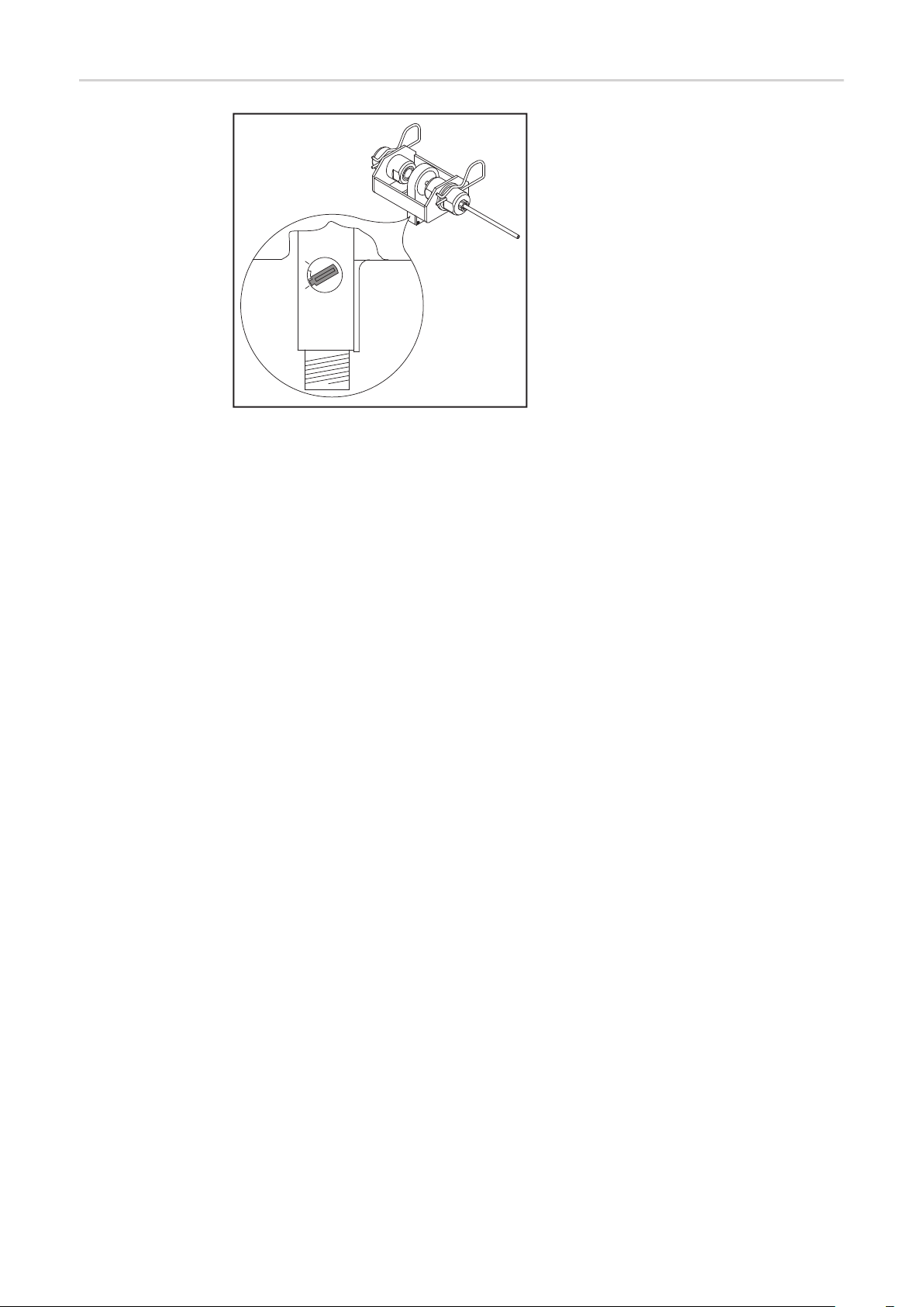
Adjusting the
OPT/i WF R wire
end ring sensor
(1)
Rotate the wire electrode in the
(3)(2)
1
opening (1) of the sensor during the
entire adjustment process
- LED (3) lights up when the sensor
detects the wire electrode
Turn the adjusting screw (2) back until
2
the LED (3) goes out
- Wire sensor is deactivated
Slowly turn the adjusting screw (2) for-
3
wards again until the LED (3) lights up
- stop turning as soon as the LED lights
up
- The sensor is now set at its lowest
sensitivity level
- This prevents the wire sensor from
being triggered accidentally
21

Operation of the
"Delay" switch
The sensor outputs a signal when it detects
the end of the wire. If the sensor then detects the wire electrode again, the signal remains on for a short period. The amount of
time the signal remains on depends on the
setting of the "Delay" switch:
- "Off" = normal signal duration
- "On" = signal duration extended by 10
ms (factory setting)
DELAY
ON OFF
22

Spis treści
Informacje ogólne ...................................................................................................................................... 25
Zakres dostawy..................................................................................................................................... 25
Warunki................................................................................................................................................. 25
Obłożenie przyłączy.............................................................................................................................. 25
Montaż czujnika pierścieniowego końca drutu OPT/i WF R ...................................................................... 27
Bezpieczeństwo.................................................................................................................................... 27
Montaż czujnika na zasobniku drutu..................................................................................................... 28
Montaż czujnika na dużej szpuli ........................................................................................................... 29
Montaż czujnika na mocowaniu zasobnika drutu spawalniczego WF MOUNTING Drum .................... 30
Podłączenie czujnika ............................................................................................................................ 31
Regulacja czujnika pierścieniowego końca drutu OPT/i WF R............................................................. 31
Zasada działania przełącznika „Delay” ................................................................................................ 32
Appendix 33
Spare parts list: OPT/i WF R Drahtende-Ringsensor ................................................................................ 34
PL
23

24

Informacje ogólne
Zakres dostawy (1) Czujnik z uchwytem
(2) Przewód połączeniowy
Warunki
(1)
(1)
WSKAZÓWKA!
Użycie czujnika pierścieniowego końca drutu OPT/i WF R jest dozwolone tylko wtedy, gdy wtyczka czujnika OPT/i Ext. jest zamontowana w stosowanym podajniku
drutu / SplitBox.
(3) Niniejszy dokument (nieprzed-
stawiony)
PL
Obłożenie przyłączy
Obłożenie przyłącza wtyczki przewodu połączeniowego
1. BN (brązowy)
2. nieużywany
3. BU (niebieski)
4. BK (czarny)
3.
2.
4.
1.
25

Obłożenie wtyczki czujnika:
1.
3.
4.
1. BN (brązowy)
4. BU (niebieski)
4. BK (czarny)
26

Montaż czujnika pierścieniowego końca drutu OPT/i
WF R
Bezpieczeństwo
OSTRZEŻENIE!
Błędy obsługi i nieprawidłowo wykonane prace mogą spowodować poważne obrażenia ciała oraz straty materialne.
Wszystkie czynności i funkcje opisane w niniejszym dokumencie mogą być wykonywane
wyłącznie przez przeszkolony personel specjalistyczny po dokładnym zapoznaniu się
z następującymi dokumentami:
► niniejszym dokumentem;
► wszystkimi instrukcjami obsługi komponentów systemu, w szczególności przepisami
dotyczącymi bezpieczeństwa.
OSTRZEŻENIE!
Porażenie prądem elektrycznym może spowodować śmierć.
Przed rozpoczęciem prac:
► Ustawić wyłącznik zasilania źródła spawalniczego w pozycji -O-.
► Odłączyć źródło spawalnicze od sieci zasilającej.
► Źródło spawalnicze musi być odłączone od sieci aż do zakończenia wszystkich prac.
Po otwarciu urządzenia za pomocą odpowiedniego przyrządu pomiarowego sprawdzić,
czy wszystkie elementy ładowane elektrycznie (np. kondensatory) są rozładowane.
PL
OSTROŻNIE!
Niebezpieczeństwo zranienia przez wychodzący drut elektrodowy.
Jeżeli w systemie spawania znajduje się szpulowy podajnik drutu, to przed rozpoczęciem
prac:
► Ustawić wyłącznik zasilania szpulowego podajnika drutu w pozycji -O-.
► Odłączyć szpulowy podajnik drutu od sieci.
► Upewnić się, że szpulowy podajnik drutu, aż do zakończenia wszystkich prac, będzie
odłączony od sieci.
OSTROŻNIE!
Niebezpieczeństwo oparzenia przez gorące komponenty systemu.
Przed rozpoczęciem pracy wszystkie rozgrzane komponenty systemu należy pozostawić
w temperaturze pokojowej (+25°C, +77°F) w celu ostygnięcia, na przykład:
► płyn chłodzący,
► komponenty systemu chłodzone wodą,
► silnik napędowy podajnika drutu.
27

Montaż czujnika
na zasobniku drutu
WSKAZÓWKA!
Aby zapewnić bezusterkową eksploatację, w bezpośrednim pobliżu czujnika poza
wykrywanym drutem elektrodowym nie mogą znajdować się inne metalowe przedmioty.
Prowadnik drutu ze stali: Prowadnik drutu z tworzywa sztuczne-
go:
1 1
1
5
1
6
5
6
2
1
4
2
1
4
3
3
28

Montaż czujnika
na dużej szpuli
WSKAZÓWKA!
Aby zapewnić bezusterkową eksploatację, w bezpośrednim pobliżu czujnika poza
wykrywanym drutem elektrodowym nie mogą znajdować się inne metalowe przedmioty.
Prowadnik drutu ze stali: Prowadnik drutu z tworzywa sztuczne-
go:
1 1
1
1
7
7
8
8
PL
2
3
1
4
2
4
1
6
3
6
5
5
29

Montaż czujnika
na mocowaniu zasobnika drutu
spawalniczego
WF MOUNTING
Drum
1
1
2
2
(1)
5
3
4
1
2
Zdemontować uchwyt (1) z czujnika
3
3
1
1
Element dystansowy zawarty w zakresie dostawy mocowania zasobnika drutu spawalniczego umieścić na
spodzie mocowanie zasobnika.
4
4
2 x TX25
1
2
3
M5 x 12 mm
4
Założyć czujnik na element dystansowy w sposób pokazany na ilustracji.
5
5
1
1
Wyregulować czujnik.
Przymocować czujnik dwiema śrubami TX25
M5 x 12 mm należącymi do zakresu dostawy mocowania zasobnika drutu spawalniczego.
6
6
1
1
Ustawić opóźnienie („Delay”).
30

Podłączenie czujnika
WSKAZÓWKA!
Podajnik drutu / SplitBox rozpoznaje czujnik podłączony do przewodu połączeniowego! Dlatego z każdym czujnikiem należy używać wyłącznie dołączonego przewodu połączeniowego — przewód połączeniowy czujnika jest oznaczony numerem
artykułu i oznaczeniem czujnika.
Regulacja czujnika pierścieniowego końca drutu
OPT/i WF R
(4)
(1)
(3)(1) (2)
(3)(2)
WSKAZÓWKA!
Wtyczkę (1) przewodu połączeniowego
podłączać jedynie do przyłączy
czujnika (2) z czerwonym
kodowaniem (3)
Podłączyć wtyczkę (1) przewodu
1
połączeniowego do przyłącza OPT/i
Ext. wtyczki czujnika (2) podajnika drutu / SplitBox.
Podłączyć wtyczkę (4) do czujnika.
2
Stosowany drut elektrodowy obracać
1
w otworze (1) czujnika w trakcie całego procesu regulacji.
- Dioda (3) świeci, gdy czujnik wy-
kryje drut elektrodowy.
Cofnąć śrubę regulacyjną (2), aż
2
dioda (3) przestanie świecić.
- Czujnik drutu jest dezaktywowa-
ny.
Obrócić śrubę regulacyjną (2) tylko na
3
tyle, aby dioda (3) znów zaczęła świecić.
- Ustawiona jest najmniejsza
czułość czujnika.
- Zapobiegnie to niepożądanemu
wyzwalaniu czujnika.
PL
31

Zasada działania
przełącznika „Delay”
ON OFF
Po osiągnięciu końca drutu czujnik generuje sygnał. Po ponownym wykryciu drutu
elektrodowego sygnał jest jeszcze aktywny
przez krótki czas. Czas trwania tego
opóźnienia jest zależny od położenia przełącznika „Delay”:
- położenie „Off” = normalny czas trwania sygnału;
- położenie „On” = czas trwania sygnału
DELAY
wydłużony o 10 ms (ustawienie fabryczne).
32

Appendix

Spare parts list: OPT/i WF R Drahtende-Ringsensor
34

35

FRONIUS INTERNATIONAL GMBH
Froniusstraße 1, A-4643 Pettenbach, Austria
E-Mail: sales@fronius.com
www.fronius.com
Under www.fronius.com/contact you will find the addresses
of all Fronius Sales & Service Partners and locations
 Loading...