


/ Perfect Charging / Perfect Welding / Solar Energy
42,0410,2088 004-26022018
OPT/i WF R Drahtende-Ringsensor
OPT/i WF R wire end ring sensor
Installationsanleitung
Ersatzteilliste
Systemerweiterung
Installations instructions
Spare parts list
System extension
DEEN

2

3
DE
Inhaltsverzeichnis
Allgemeines ............................................................................................................................................... 5
Lieferumfang......................................................................................................................................... 5
Voraussetzungen.................................................................................................................................. 5
Anschlussbelegungen........................................................................................................................... 5
OPT/i WF R Drahtende-Ringsensor montieren ......................................................................................... 7
Sicherheit.............................................................................................................................................. 7
Sensor auf ein Drahtfass montieren ..................................................................................................... 8
Sensor auf eine Großspule montieren.................................................................................................. 9
Sensor auf die Drahtfass-Aufnahme WF MOUNTING Drum montieren.............................................. 10
Sensor anschließen .............................................................................................................................. 11
OPT/i WF R Drahtende-Ringsensor einstellen ..................................................................................... 11
Funktionsweise des Schalters "Delay" ................................................................................................. 11
Appendix 23
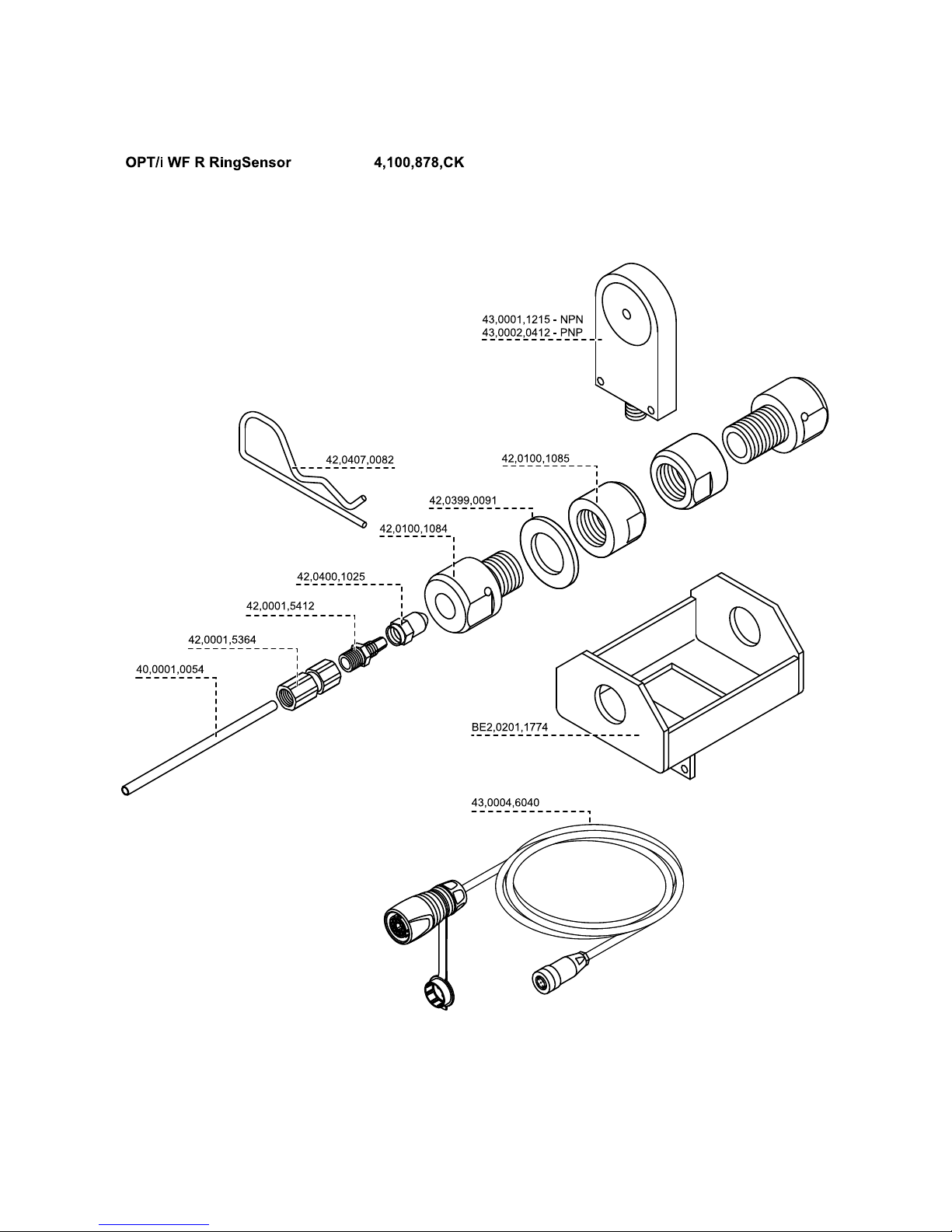
Spare parts list: OPT/i WF R Drahtende-Ringsensor ................................................................................ 24

4

5
DE
Allgemeines
Lieferumfang (1) Sensor mit Halterung
(2) Verbindungskabel
(3) dieses Dokument (nicht abgebil-
det)
Voraussetzungen
Anschlussbelegungen
(1)
(1)
HINWEIS! OPT/i WF R Drahtende-Ringsensor kann nur verwendet werden,
wenn OPT/i Ext. Sensorstecker in dem verwendeten Drahtvorschub / der verwendeten SplitBox eingebaut ist.
Anschlussbelegung des Steckers vom Verbindungskabel:
1. BN (braun)
2. nicht verwendet
3. BU (blau)
4. BK (schwarz)
1.
2.
3.
4.

6
Anschlussbelegung des Sensors:
1. BN (braun)
4.. BU (blau)
4. BK (schwarz)
1.
3.
4.

7
DE
OPT/i WF R Drahtende-Ringsensor montieren
Sicherheit
WARNUNG! Fehlbedienung und fehlerhaft durchgeführte Arbeiten können
schwerwiegende Personen- und Sachschäden verursachen.
Alle in diesem Dokument beschriebenen Arbeiten und Funktionen dürfen nur von
geschultem Fachpersonal ausgeführt werden, wenn folgende Dokumente vollständig gelesen und verstanden wurden:
- dieses Dokument
- sämtliche Bedienungsanleitungen der Systemkomponenten, insbesondere
Sicherheitsvorschriften
WARNUNG! Ein elektrischer Schlag kann tödlich sein. Vor Beginn der Arbeiten:
- Netzschalter der Stromquelle in Stellung - O - schalten
- Stromquelle vom Netz trennen
- sicherstellen, dass die Stromquelle bis zum Abschluss aller Arbeiten vom
Netz getrennt bleibt
Nach dem Öffnen des Gerätes mit Hilfe eines geeigneten Messgerätes sicherstellen, dass elektrisch geladene Bauteile (z.B. Kondensatoren) entladen sind.
VORSICHT! Verletzungsgefahr durch austretende Drahtelektrode. Ist ein Abspul-Drahtvorschub im Schweißsystem vorhanden, vor Beginn der Arbeiten:
- Netzschalter des Abspul-Drahtvorschubes in Stellung - O - schalten
- Abspul-Drahtvorschub vom Netz trennen
- sicherstellen, dass der Abspul-Drahtvorschub bis zum Abschluss aller Arbeiten vom Netz getrennt bleibt
VORSICHT! Verletzungsgefahr durch heiße Systemkomponenten. Vor Beginn
der Arbeiten alle heißen Systemkomponenten auf Zimmertemperatur (+25 °C,
+77 °F) abkühlen lassen, beispielsweise:
- Kühlmittel
- wassergekühlte Systemkomponenten
- Antriebsmotor des Drahtvorschubes

8
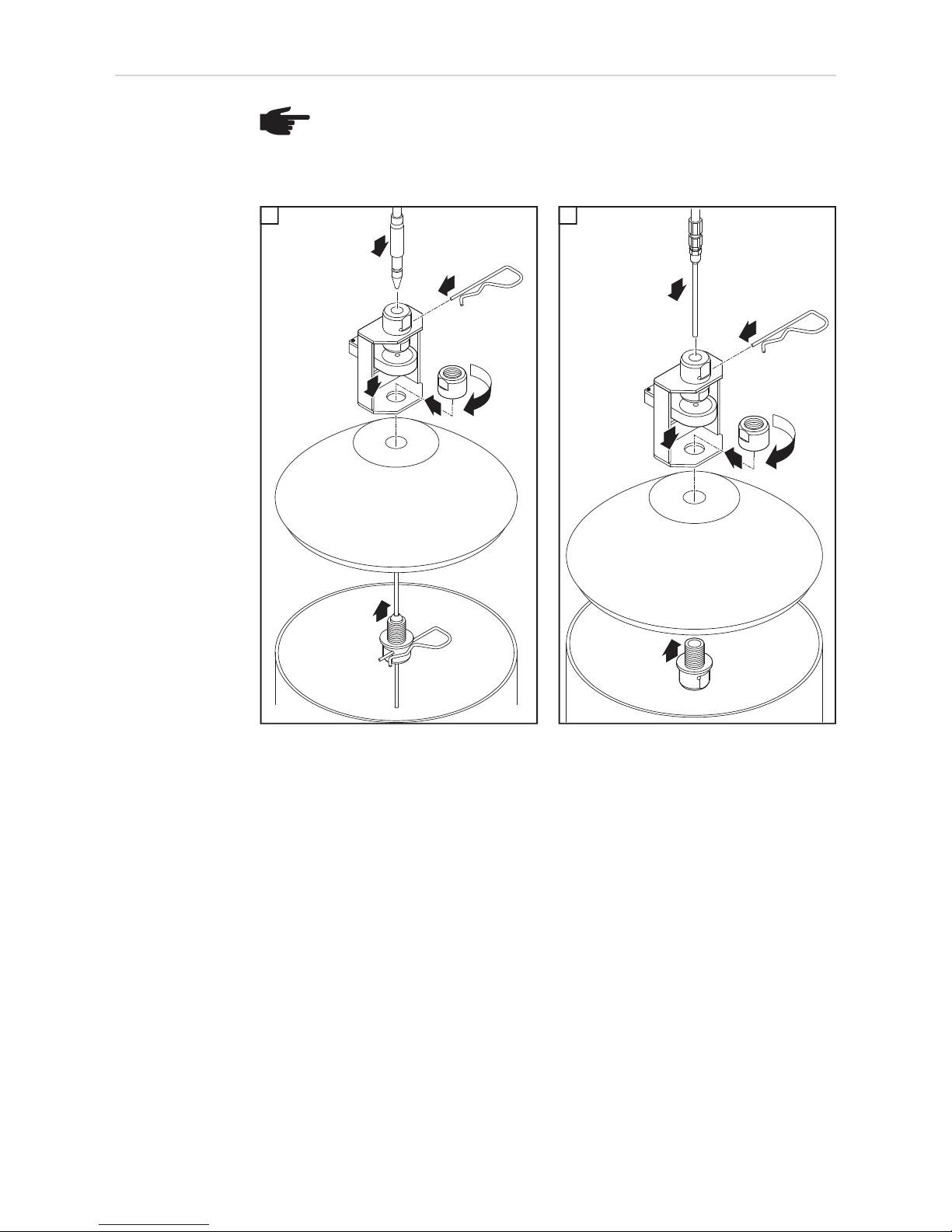
Sensor auf ein
Drahtfass montieren
HINWEIS! Um einen störungsfreien Betrieb zu gewährleisten, dürfen sich in un-
mittelbarer Nähe des Sensors außer der zu detektierenden Drahtelektrode keine
metallischen Gegenstände befinden.
Draht-Führungsseele aus Stahl: Draht-Führungsseele aus Kunststoff:
1 1
6
5
2
4
3
1
1
6
5
2
4
3
1
1

9
DE
Sensor auf eine
Großspule montieren
HINWEIS! Um einen störungsfreien Betrieb zu gewährleisten, dürfen in unmittel-
barer Nähe des Sensors außer der zu detektierenden Drahtelektrode keine metallischen Gegenstände angebracht sein.
Draht-Führungsseele aus Stahl: Draht-Führungsseele aus Kunststoff:
1 1
8
7
2
1
4
3
5
6
1
8
7
2
4
3
5
6
1
1

10
Sensor auf die
Drahtfass-Aufnahme WF
MOUNTING Drum
montieren
1
Halterung (1) vom Sensor abmontieren
2
Distanzstück aus dem Lieferumfang der DrahtfassAufnahme an der Unterseite der Drahtfass-Aufnahme
ansetzen
3
Sensor wie abgebildet auf das Distanzstück aufsetzen4Sensor mit 2 Schrauben TX25 M5 x 12 mm aus dem
Lieferumfang der Drahtfass-Aufnahme fixieren
5
Sensor einstellen
6
„Delay“ einstellen
5
4
1
3
2
(1)
1
1
2
1
3
1
4
2 x TX25
M5 x 12 mm
2
3
4
1
1
5
1
1
6

11
DE
Sensor anschließen
Stecker (1) vom Verbindungskabel an
einen Anschluss OPT/i Ext. Sensorstecker (2) des Drahtvorschubes / der
SplitBox anschließen
Stecker (4) an den Sensor anschließen
OPT/i WF R Drahtende-Ringsensor
einstellen
Verwendete Drahtelektrode in der Öffnung (1) des Sensors während des gesamten Einstellvorganges kreisen
- LED (3) leuchtet, wenn der Sensor
die Drahtelektrode erkennt
Einstellschraube (2) zurückdrehen, bis
die LED (3) erlischt
- Drahtsensor ist deaktiviert
Einstellschraube (2) nur so weit vordrehen, bis die LED (3) wieder aufleuchtet
- Der Sensor ist nun mit der geringsten Sensibilität eingestellt
- Ungewolltes Ansprechen des
Sensors wird somit verhindert
Funktionsweise
des Schalters
"Delay"
Ist das Drahtende erreicht, gibt der Sensor
ein Signal aus. Wird die Drahtelektrode anschließend wieder erkannt, verbleibt das
Signal noch für kurze Zeit. Die Dauer dieser
Verzögerung ist von der Stellung des
Schalters „Delay“ abhängig:
- Stellung „Off“ = normale Signaldauer
- Stellung „On“ = Signaldauer um 10 ms
verlängert (Werkseinstellung)
HINWEIS! Der Drahtvorschub / die SplitBox erkennt den angesteckten Sensor
am Verbindungskabel! Daher für jeden Sensor nur das mitgelieferte Verbindungskabel verwenden - das Verbindungskabel des Sensors ist mit der Artikelnummer und Bezeichnung des Sensors markiert.
(3)(1) (2)
(4)
HINWEIS! Den Stecker (1) des
Verbindungskabels nur an Sensoranschlüsse (2) mit einer roten
Codierung (3) anschließen.
1
2
(1)
(3)(2)
1
2
3
ON OFF
DELAY

12

13
EN
Contents
General ...................................................................................................................................................... 15
Scope of supply .................................................................................................................................... 15
Prerequisites......................................................................................................................................... 15
Pin assignments.................................................................................................................................... 15
Fitting the OPT/i WF R wire end ring sensor ............................................................................................. 17
Safety.................................................................................................................................................... 17
Fitting the sensor to a wire drum........................................................................................................... 18
Fitting the sensor to a large spool......................................................................................................... 19
Fitting the sensor to the WF MOUNTING Drum holder ........................................................................ 20
Connecting the sensor.......................................................................................................................... 21
Adjusting the OPT/i WF R wire end ring sensor ...................................................................................21
Operation of the "Delay" switch ........................................................................................................... 22
Appendix 23
Spare parts list: OPT/i WF R Drahtende-Ringsensor ................................................................................ 24

14

15
EN
General
Scope of supply (1) Sensor with holder
(2) Connecting cable
(3) This document (not shown)
Prerequisites
Pin assignments
(1)
(1)
NOTE! The OPT/i WF R wire end ring sensor can only be used if an OPT/i ext.
sensor plug has been installed in the respective wirefeeder or SplitBox.
Pin assignment of connecting cable plug:
1. BN = brown
2. Not used
3. BU = blue
4. BK = black
1.
2.
3.
4.

16
Pin assignment of sensor:
1. BN = brown
4. BU = blue
4. BK = black
1.
3.
4.

17
EN
Fitting the OPT/i WF R wire end ring sensor
Safety
WARNING! Incorrect operation or shoddy workmanship can cause serious injury
or damage.
All functions described in this document may only be carried out by trained and
qualified personnel after they have fully read and understood the following documents:
- this document
- all the operating instructions for the system components, especially the safety rules
WARNING! An electric shock can be fatal. Before starting work:
- turn the power source mains switch to the "O" position
- disconnect the power source from the mains
- ensure that the power source remains disconnected from the mains until all
work has been completed
After opening the device, use a suitable measuring instrument to check that electrically charged components (e.g. capacitors) have been discharged.
CAUTION! Risk of injury from wire electrode emerging at speed. If the welding
system contains an unreeling wirefeeder, also carry out the following actions before starting work:
- turn the mains switch of the unreeling wirefeeder to the "O" position
- disconnect the unreeling wirefeeder from the mains
- ensure that the unreeling wirefeeder remains disconnected from the mains
until all work has been completed
CAUTION! Risk of scalding from hot system components. Before starting work,
allow all hot system components to cool down to room temperature (+25°C,
+77°F). For example:
- coolant
- water-cooled system components
- wirefeeder drive motor
18
Fitting the sensor
to a wire drum
NOTE! To ensure trouble-free operation, ensure that there are no metal objects,
apart from the wire electrode being monitored, in the immediate vicinity of the sensor.
Steel inner liner: Plastic inner liner:
1 1
6
5
2
4
3
1
1
6
5
2
4
3
1
1

19
EN
Fitting the sensor
to a large spool
NOTE! To ensure trouble-free operation, no metal objects, apart from the wire
electrode being monitored, may be fitted in the immediate vicinity of the sensor.
Steel inner liner: Plastic inner liner:
1 1
8
7
2
1
4
3
5
6
1
8
7
2
4
3
5
6
1
1

20
Fitting the sensor
to the WF
MOUNTING Drum
holder
1
Remove the holder (1) from the sensor
2
Attach the spacer supplied with the wire drum holder
to the underside of the wire drum holder
3
Place the sensor on the spacer as shown
4
Secure the sensor with the two M5 x 12 mm TX25
screws supplied with the wire drum holder
5
Adjust the sensor
6
Set the "Delay"
5
4
1
3
2
(1)
1
1
2
1
3
1
4
2 x TX25
M5 x 12 mm
2
3
4
1
1
5
1
1
6

21
EN
Connecting the
sensor
Connect the plug (1) on the connecting
cable to an OPT/i ext. sensor plug (2)
connection of the wirefeeder/SplitBox
Connect the plug (4) to the sensor
Adjusting the
OPT/i WF R wire
end ring sensor
Rotate the wire electrode in the
opening (1) of the sensor during the
entire adjustment process
- LED (3) lights up when the sensor
detects the wire electrode
Turn the adjusting screw (2) back until
the LED (3) goes out
- Wire sensor is deactivated
Slowly turn the adjusting screw (2) forwards again until the LED (3) lights up
- stop turning as soon as the LED lights
up
- The sensor is now set at its lowest
sensitivity level
- This prevents the wire sensor from
being triggered accidentally
NOTE! The wirefeeder/SplitBox recognises that there is a sensor connected to
the connecting cable. Each sensor is supplied with its own connecting cable,
which must be used. The sensor connecting cable will be marked with the item
number and name of sensor.
(3)(1) (2)
(4)
NOTE! The plug (1) of the connecting cable may only be connected to the sensor connections
(2) that are colour-coded red (3).
1
2
(1)
(3)(2)
1
2
3

22
Operation of the
"Delay" switch
The sensor outputs a signal when it detects
the end of the wire. If the sensor then detects the wire electrode again, the signal remains on for a short period. The amount of
time the signal remains on depends on the
setting of the "Delay" switch:
- "Off" = normal signal duration
- "On" = signal duration extended by 10
ms (factory setting)
ON OFF
DELAY

Appendix
24
Spare parts list: OPT/i WF R Drahtende-Ringsensor

25

26

27

FRONIUS INTERNATIONAL GMBH
Froniusplatz 1, A-4600 Wels, Austria
Tel: +43 (0)7242 241-0, Fax: +43 (0)7242 241-3940
E-Mail: sales@fronius.com
www.fronius.com
www.fronius.com/addresses
Under http://www.fronius.com/addresses you will find all addresses
of our Sales & service partners and Locations
 Loading...