


Fronius prints on elemental chlorine free paper (ECF) sourced from certified sustainable forests (FSC).
/ Perfect Charging / Perfect Welding / Solar Energy
OPT/i WF Gasdurchfluss-Sensor
OPT/i WF gas flow sensor
Installationsanleitung
DE
Systemerweiterung
Installation instructions
System extension
EN-US
42,0410,2413 006-23122020


Inhaltsverzeichnis
Lieferumfang 4
Lieferumfang 4
OPT/i WF Gasdurchfluss-Sensor in WF 15/25/30i einbauen 5
Sicherheit 5
Vorbereitungen 6
OPT/i WF Gasdurchfluss-Sensor in WF 15/25/30i einbauen 6
Abschließende Tätigkeiten 9
OPT/i WF Gasdurchfluss-Sensor in WF15/25/30i R und in SB 500i R einbauen 10
Sicherheit 10
Vorbereitung 11
Einbauübersicht 11
OPT/i WF Gasdurchfluss-Sensor in WF15/25/30i R und in SB 500i R einbauen 12
Abschließende Tätigkeiten 16
OPT/i WF Gasdurchfluss-Sensor in SB 60i R einbauen 17
Sicherheit 17
Vorbereitung 17
Einbaulage 18
OPT/i WF Gasdurchfluss-Sensor in SB 60i R einbauen 19
Abschließende Tätigkeiten 22
OPT/i Gasdurchfluss-Sensor in SB 360i LaserHybrid einbauen 23
Sicherheit 23
Vorbereitung 23
OPT/i Gasdurchfluss-Sensor einbauen 24
Abschließende Tätigkeiten 25
Korrekturfaktoren der gängigsten Schutzgase 26
DE
3

Lieferumfang
(1) (2)
(3)(4)(5)(6)(7)(10) (8)
(9)
(12)
(11)
Lieferumfang
(1) Gasschlauch
(2) Kabel für Gassensor
(3) Halteblech
(4) 4 Steckanschlüsse
(5) Gassensor
(6) 4 Schrauben TX 20
(7) 2 Innensechskant-Schrauben
(8) 2 Kreuzschlitz-Schrauben
(9) 2 Schrauben TX 25
(10) 2 Schrauben TX 10
(11) 2 Sechskantmuttern M3, SW 5,5 mm
(12) 2 Scheiben
4

OPT/i WF Gasdurchfluss-Sensor in WF 15/25/30i
einbauen
Sicherheit
WARNUNG!
Gefahr durch Fehlbedienung und fehlerhaft durchgeführte Arbeiten.
Schwerwiegende Personen- und Sachschäden können die Folge sein.
Alle in diesem Dokument beschriebenen Arbeiten und Funktionen dürfen nur von
▶
geschultem Fachpersonal ausgeführt werden.
Dieses Dokument lesen und verstehen.
▶
Sämtliche Bedienungsanleitungen der Systemkomponenten, insbesondere Sicher-
▶
heitsvorschriften lesen und verstehen.
WARNUNG!
Gefahr durch elektrischen Strom.
Schwere Verletzungen oder Tod können die Folge sein.
Netzschalter der Stromquelle in Stellung - O - schalten und die Stromquelle vom
▶
Netz trennen
Alle beteiligten Geräte und Komponenten gegen Wiedereinschalten sichern.
▶
Nach dem Öffnen des Gerätes mit Hilfe eines geeigneten Messgerätes sicherstel-
▶
len, dass elektrisch geladene Bauteile (beispielsweise Kondensatoren) entladen
sind.
DE
WARNUNG!
Gefahr durch elektrischen Strom wegen unzureichender Schutzleiter-Verbindung.
Schwerwiegende Personen- und Sachschäden können die Folge sein.
Immer die originalen Gehäuse-Schrauben in der ursprünglichen Anzahl verwenden.
▶
VORSICHT!
Verletzungsgefahr durch heiße Systemkomponenten.
Vor Beginn der Arbeiten alle heißen Systemkomponenten auf Zimmertemperatur (+25
°C, +77 °F) abkühlen lassen, beispielsweise:
Kühlmittel
▶
wassergekühlte Systemkomponenten
▶
Antriebsmotor des Drahtvorschubes
▶
5
Vorbereitungen
(1) (2)
(1)
Sämtliche Verbindungen des Draht-
1
vorschubes von allen anderen Systemkomponenten trennen
Draht- oder Korbspule dem Drahtvor-
2
schub entnehmen
Drahtvorschub auf einer geeigneten
3
Unterlage ablegen
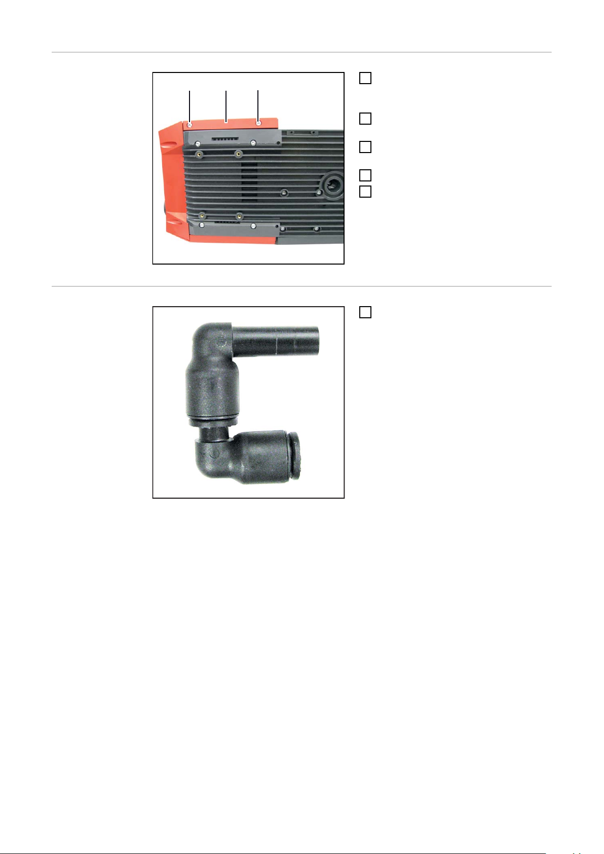
2 Schrauben TX 25 (1) lösen
4
Seitenteil rechts (2) entfernen
5
OPT/i WF Gasdurchfluss-Sensor in WF
15/25/30i einbauen
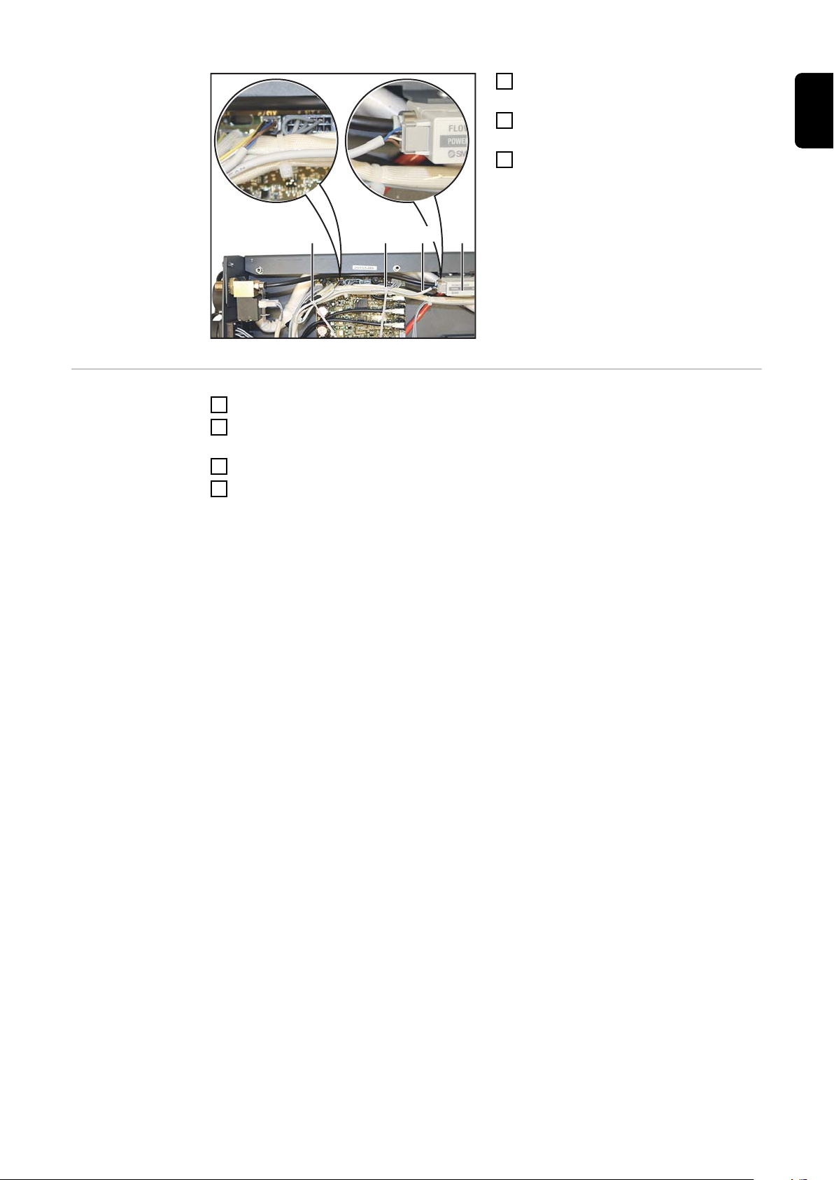
2 Steckanschlüsse wie abgebildet
1
ineinander stecken, Arbeitsschritt 2
Mal ausführen
6

(6) (7)(10) (8)(10) (9)
Vorbereitete Steckanschlüsse (6) und (7) wie abgebildet in den Gassensor (8) ste-
(11)
(4) (7)
2
cken
Gassensor (8) wie abgebildet auf das Halteblech (9) aufsetzen und mittels zwei
3
Innensechskant-Schrauben (10) festschrauben
- SW 2,5 mm
DE
Bestehenden Gasschlauch (4) am Anschluss (7) anstecken
4
Stecker des mitgelieferten Kabels am Anschluss (11) des Gassensors (8) anstecken
5
7
(8) (12)(12)
Gassensor (8) mitsamt Halteblech in den Drahtvorschub einsetzen und mittels zwei
(13) (14)(6)
6
Schrauben TX 25 (12) festschrauben
- Anzugsmoment = 2,5 Nm
Mitgelieferten Gasschlauch (13) in Anschluss (6) und (14) stecken
7
8

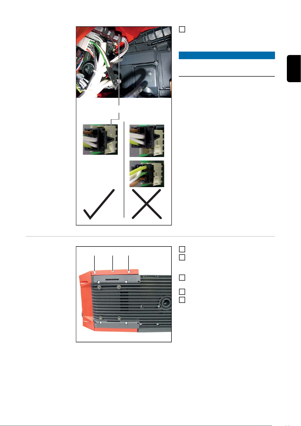
(15)
Stecker (15) des mitgelieferten Kabels
(1) (2)
(1)
8
im Drahtvorschub anstecken
- am Print SR 63, Buchse X15
HINWEIS!
Den Stecker (15) nur wie im Detail dargestellt anstecken.
DE
Abschließende
Tätigkeiten
Seitenteil (2) einsetzen
1
2 Schrauben 5 x 14 mm (1) mittels
2
Schraubendreher TX 25 festschrauben
- Anzugsmoment = 1,9 Nm
Drahtvorschub wieder in seine Aus-
3
gangsposition bringen
Draht- oder Korbspule einsetzen
4
Verbindungen mit anderen System-
5
komponenten wieder herstellen
9

OPT/i WF Gasdurchfluss-Sensor in WF15/25/30i R
und in SB 500i R einbauen
Sicherheit
WARNUNG!
Gefahr durch Fehlbedienung und fehlerhaft durchgeführte Arbeiten.
Schwerwiegende Personen- und Sachschäden können die Folge sein.
Alle in diesem Dokument beschriebenen Arbeiten und Funktionen dürfen nur von
▶
geschultem Fachpersonal ausgeführt werden.
Dieses Dokument lesen und verstehen.
▶
Sämtliche Bedienungsanleitungen der Systemkomponenten, insbesondere Sicher-
▶
heitsvorschriften lesen und verstehen.
WARNUNG!
Gefahr durch elektrischen Strom.
Schwere Verletzungen oder Tod können die Folge sein.
Netzschalter der Stromquelle in Stellung - O - schalten und die Stromquelle vom
▶
Netz trennen
Alle beteiligten Geräte und Komponenten gegen Wiedereinschalten sichern.
▶
Nach dem Öffnen des Gerätes mit Hilfe eines geeigneten Messgerätes sicherstel-
▶
len, dass elektrisch geladene Bauteile (beispielsweise Kondensatoren) entladen
sind.
WARNUNG!
Gefahr durch elektrischen Strom wegen unzureichender Schutzleiter-Verbindung.
Schwerwiegende Personen- und Sachschäden können die Folge sein.
Immer die originalen Gehäuse-Schrauben in der ursprünglichen Anzahl verwenden.
▶
VORSICHT!
Verletzungsgefahr durch heiße Systemkomponenten.
Vor Beginn der Arbeiten alle heißen Systemkomponenten auf Zimmertemperatur (+25
°C, +77 °F) abkühlen lassen, beispielsweise:
Kühlmittel
▶
wassergekühlte Systemkomponenten
▶
Antriebsmotor des Drahtvorschubes
▶
10

Vorbereitung
(1)
(1) (1)
(1)
(3)
(2)
Sämtliche Verbindungen des Gerätes von allen anderen Systemkomponenten tren-
1
nen
Gerät auf einer geeigneten Unterlage ablegen
2
4 Schrauben TX 20 (1) lösen
3
Abdeckung (2) öffnen
4
Gehäuseabdeckung (3) wie abgebildet vom Gerät abziehen
5
DE
Einbauübersicht OPT/i Gasregler kann in die nachfolgenden Geräte eingebaut werden:
- alle Varianten der Roboter-Drahtvorschübe WF 15/25/30i R
- alle Varianten der SplitBox SB 500i R
HINWEIS!
Der Einbau von OPT/i Gasregler wird nachfolgend mit dem WF 25i R dargestellt.
Bei den anderen kompatiblen Geräten funktioniert der Einbau gleich, allerdings befinden
sich die relevanten Komponenten/Anschlüsse in den einzelnen Geräten teilweise an
unterschiedlichen Positionen. Die Kern-Arbeitsschritte sind immer gleich:
im Gerät eingebautes Gas-Magnetventil entfernen
1
neues Gas-Magnetventil einbauen
2
Gassensor einbauen
3
OUT-Anschluss des Gassensors mittels Gasschlauch mit Motorplatte verbinden
4
IN-Anschluss des Gassensors mittels Gasschlauch mit Gas-Magnetventil verbinden
5
Details zum Einbau dem nachfolgenden Abschnitt entnehmen.
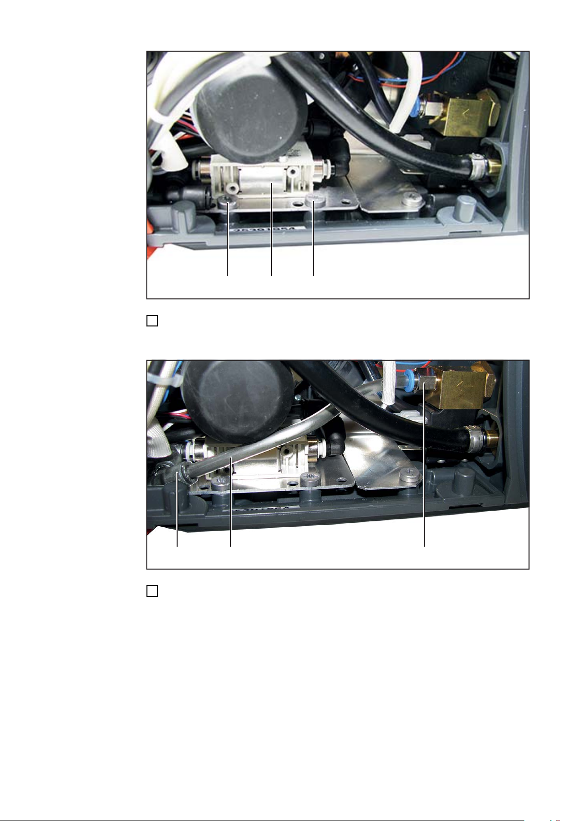
Übersicht, OPT/i Gasregler korrekt eingebaut:
11

Von hinten gesehen, Gas-Magnetventil links (linke
Gerätevariante)
Von hinten gesehen, Gas-Magnetventil rechts (rechte
Gerätevariante)
OPT/i WF Gasdurchfluss-Sensor in
WF15/25/30i R
und in SB 500i R
einbauen
HINWEIS!
Die Steckanschlüsse sind nicht bei
allen Geräten notwendig.
Um zu überprüfen, ob die Steckanschlüsse notwendig sind ist es ratsam,
den Gassensor (8) mitsamt Halteblech
(10) in die spätere Montageposition zu
bringen und die Verlegung der Gasschläuche abzuklären.
2 Steckanschlüsse wie abgebildet
1
ineinander stecken
12

(9)(7)
(11) (11) (10)(8)
Falls notwendig: vorbereitete Steckanschlüsse (7) wie abgebildet in den Gassensor
(12) (8)(12) (12)(12)
2
(8) stecken
Falls notwendig: Steckanschluss (9) in den Gassensor (8) stecken
3
Gassensor (8) wie abgebildet auf das Halteblech (10) aufsetzen und mittels zwei
4
Kreuzschlitz-Schrauben (11) festschrauben
DE
Gassensor (8) mitsamt Halteblech in den Drahtvorschub einsetzen und mittels vier
5
Schrauben TX 20 (12) festschrauben
- Anzugsmoment = 2,5 Nm
13
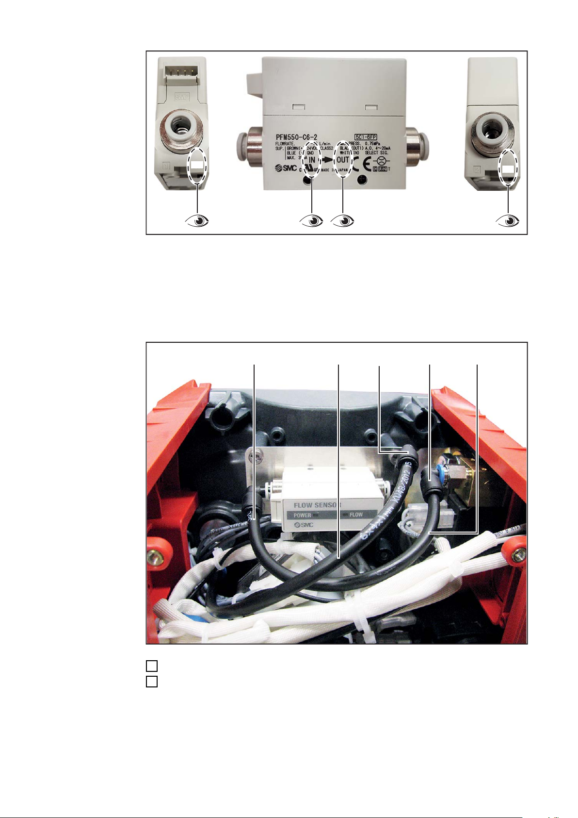
IN
OUT
Der Gassensor (8) muss mit den Gasschläuchen (4) und (13) immer wie folgt mit dem
(15) (4) (13)(14)(7)
Gas-Magnetventil / der Motorplatte verbunden werden
- Gassensor-Anschluss IN -> Gasmagnet-Ventil (5)
- Gassensor-Anschluss OUT -> Motorplatte
- für weitere Informationen siehe auch Abschnitt „Einbauübersicht“ am Anfang des
Kapitels „OPT/i Gasregler einbauen: alle Varianten der Roboter-Drahtvorschübe
WF15/25/30i R, alle Varianten der SplitBox SB 500i R“
14
Vorhandenen Gasschlauch (4) an Anschluss (7) anschließen
6
Mitgelieferten Gasschlauch (13) in Anschluss (14) und (15) stecken
7

(16) (8)
(17)
DE
Stecker (16) des mitgelieferten Kabels am Gassensor (8) anstecken
8
6-poligen Stecker des mitgelieferten Kabels im Gerät anstecken
9
- am Print SR63, Buchse X15 (17)
HINWEIS!
6-poligen Stecker des mitgelieferten Kabels nur wie im Detail dargestellt anstecken.
15

Abschließende
(3)
(2)
(1)
(1) (1)
(1)
Tätigkeiten
HINWEIS!
Beim Montieren der Gehäuseabdeckung sicherstellen, dass Kabel und Schläuche
nicht geknickt, eingeklemmt, abgescheuert oder auf andere Weise beschädigt werden.
Gehäuseabdeckung (3) wie abgebildet bis auf Anschlag auf das Gerät aufschieben
1
4 Schrauben TX 20 (1) festschrauben
2
Abdeckung (2) schließen
3
Gerät in seine Ausgangsposition bringen
4
Verbindungen mit anderen Systemkomponenten herstellen
5
16

OPT/i WF Gasdurchfluss-Sensor in SB 60i R einbauen
Sicherheit
WARNUNG!
Gefahr durch Fehlbedienung und fehlerhaft durchgeführte Arbeiten.
Schwerwiegende Personen- und Sachschäden können die Folge sein.
Alle in diesem Dokument beschriebenen Arbeiten und Funktionen dürfen nur von
▶
geschultem Fachpersonal ausgeführt werden.
Dieses Dokument lesen und verstehen.
▶
Sämtliche Bedienungsanleitungen der Systemkomponenten, insbesondere Sicher-
▶
heitsvorschriften lesen und verstehen.
WARNUNG!
Gefahr durch elektrischen Strom.
Schwere Verletzungen oder Tod können die Folge sein.
Netzschalter der Stromquelle in Stellung - O - schalten und die Stromquelle vom
▶
Netz trennen
Alle beteiligten Geräte und Komponenten gegen Wiedereinschalten sichern.
▶
Nach dem Öffnen des Gerätes mit Hilfe eines geeigneten Messgerätes sicherstel-
▶
len, dass elektrisch geladene Bauteile (beispielsweise Kondensatoren) entladen
sind.
DE
Vorbereitung
WARNUNG!
Gefahr durch elektrischen Strom wegen unzureichender Schutzleiter-Verbindung.
Schwerwiegende Personen- und Sachschäden können die Folge sein.
Immer die originalen Gehäuse-Schrauben in der ursprünglichen Anzahl verwenden.
▶
VORSICHT!
Verletzungsgefahr durch heiße Systemkomponenten.
Vor Beginn der Arbeiten alle heißen Systemkomponenten auf Zimmertemperatur (+25
°C, +77 °F) abkühlen lassen, beispielsweise:
Kühlmittel
▶
wassergekühlte Systemkomponenten
▶
Antriebsmotor des Drahtvorschubes
▶
Sämtliche Verbindungen des Gerätes von allen anderen Systemkomponenten tren-
1
nen
Gerät vom Roboter demontieren
2
Gerät auf einer geeigneten Unterlage mit der durchsichtigen Abdeckung nach unten
3
ablegen
17

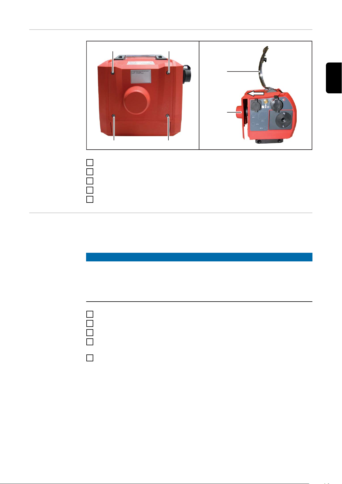
(1)
(2)
(1)
(1)
(1)
(1)
6 Schrauben TX25 (1) lösen
4
Abdeckung (2) abnehmen
5
Einbaulage
HINWEIS!
Der Einbau von OPT/i Gasregler wird nachfolgend mit der rechten SB 60i R
Geräteausführung dargestellt.
Bei der linken SB 60i R Geräteausführung funktioniert der Einbau gleich, allerdings
befinden sich die relevanten Komponenten/Anschlüsse an unterschiedlichen Positionen.
Die Kern-Arbeitsschritte sind immer gleich:
im Gerät eingebautes Gas-Magnetventil entfernen
1
neues Gas-Magnetventil einbauen
2
Gassensor einbauen
3
IN-Anschluss des Gassensors mittels Gasschlauch mit Gas-Magnetventil verbinden
4
OUT-Anschluss des Gassensors mittels Gasschlauch dem Anschluss Schweißbren-
5
ner (FSC) verbinden
Details zum Einbau dem nachfolgenden Abschnitt entnehmen.
18

OPT/i WF Gas-
IN
OUT
durchfluss-Sensor in SB 60i R
einbauen
DE
Der Gassensor (6) muss mittels den Gasschläuchen immer wie folgt mit dem GasMagnetventil / dem Anschluss Schweißbrenner (FSC) verbunden werden
- Gassensor-Anschluss IN -> Gasmagnet-Ventil (11)
- Gassensor-Anschluss OUT -> Anschluss Schweißbrenner (FSC)
- für weitere Informationen siehe auch Abschnitt „Einbauübersicht“ am Anfang des
Kapitels „OPT/i Gasregler einbauen: SB 60i R“
19
(1)(8)(9)(10) (6)(7)
Gassensor (6) wie abgebildet in das Gerät einsetzen und mittels 2 mitgelieferten
1
Schrauben TX 10 (7) festschrauben
Gasschlauch (1) so abschneiden, dass er wie abgebildet am Anschluss OUT (8) des
2
Gassensors (6) angeschlossen werden kann. Den abgeschnittenen Teil des Gasschlauches aufbewahren
Gasschlauch (1) am Anschluss (8) des Gassensors (6) anschließen
3
Mitgeliefertes Kabel (9) an der Buchse (10) des Gassensors (6) anschließen
4
20

(9) (6)
(11)
DE
6-poligen Stecker des mitgelieferten Kabels (9) im Gerät anstecken
5
- am Print SR63, Buchse X15 (11)
HINWEIS!
6-poligen Stecker des mitgelieferten Kabels nur wie im Detail dargestellt anstecken.
21

(1) (14) (6)
Gasschlauch (1) am Anschluss IN (14) des Gassensors (6) anschließen
(1)
(2)
(1)
(1)
(1)
(1)
6
Abschließende
Tätigkeiten
Abdeckung (2) einsetzen
1
Abdeckung mit 6 Schrauben TX25 (1)
2
festschrauben
Anzugsmoment = 3 Nm
Gerät am Roboter festschrauben (4 x Innensechskant-Schraube M6 x 60 mm)
3
Verbindungen mit den anderen Systemkomponenten herstellen
4
22

OPT/i Gasdurchfluss-Sensor in SB 360i LaserHybrid einbauen
Sicherheit
Gefahr durch Fehlbedienung und fehlerhaft durchgeführte Arbeiten.
Schwerwiegende Personen- und Sachschäden können die Folge sein.
Alle in diesem Dokument beschriebenen Arbeiten und Funktionen dürfen nur von
▶
geschultem Fachpersonal ausgeführt werden.
Dieses Dokument lesen und verstehen.
▶
Sämtliche Bedienungsanleitungen der Systemkomponenten, insbesondere Sicher-
▶
heitsvorschriften lesen und verstehen.
Gefahr durch elektrischen Strom.
Schwere Verletzungen oder Tod können die Folge sein.
Netzschalter der Stromquelle in Stellung - O - schalten und die Stromquelle vom
▶
Netz trennen
Alle beteiligten Geräte und Komponenten gegen Wiedereinschalten sichern.
▶
Nach dem Öffnen des Gerätes mit Hilfe eines geeigneten Messgerätes sicherstel-
▶
len, dass elektrisch geladene Bauteile (beispielsweise Kondensatoren) entladen
sind.
DE
WARNUNG!
WARNUNG!
Vorbereitung
WARNUNG!
Gefahr durch elektrischen Strom wegen unzureichender Schutzleiter-Verbindung.
Schwerwiegende Personen- und Sachschäden können die Folge sein.
Immer die originalen Gehäuse-Schrauben in der ursprünglichen Anzahl verwenden.
▶
VORSICHT!
Verletzungsgefahr durch heiße Systemkomponenten.
Vor Beginn der Arbeiten alle heißen Systemkomponenten auf Zimmertemperatur (+25
°C, +77 °F) abkühlen lassen, beispielsweise:
Kühlmittel
▶
wassergekühlte Systemkomponenten
▶
Antriebsmotor des Drahtvorschubes
▶
Sämtliche Verbindungen des Gerätes von allen anderen Systemkomponenten tren-
1
nen
Gerät vom Roboter demontieren
2
7 Schrauben TX25 entfernen
3
Abdeckung abnehmen
4
23

OPT/i Gasdurch-
(7)
(7)
(8)
(9) (10)
(9)
(10)
(8)
(5)
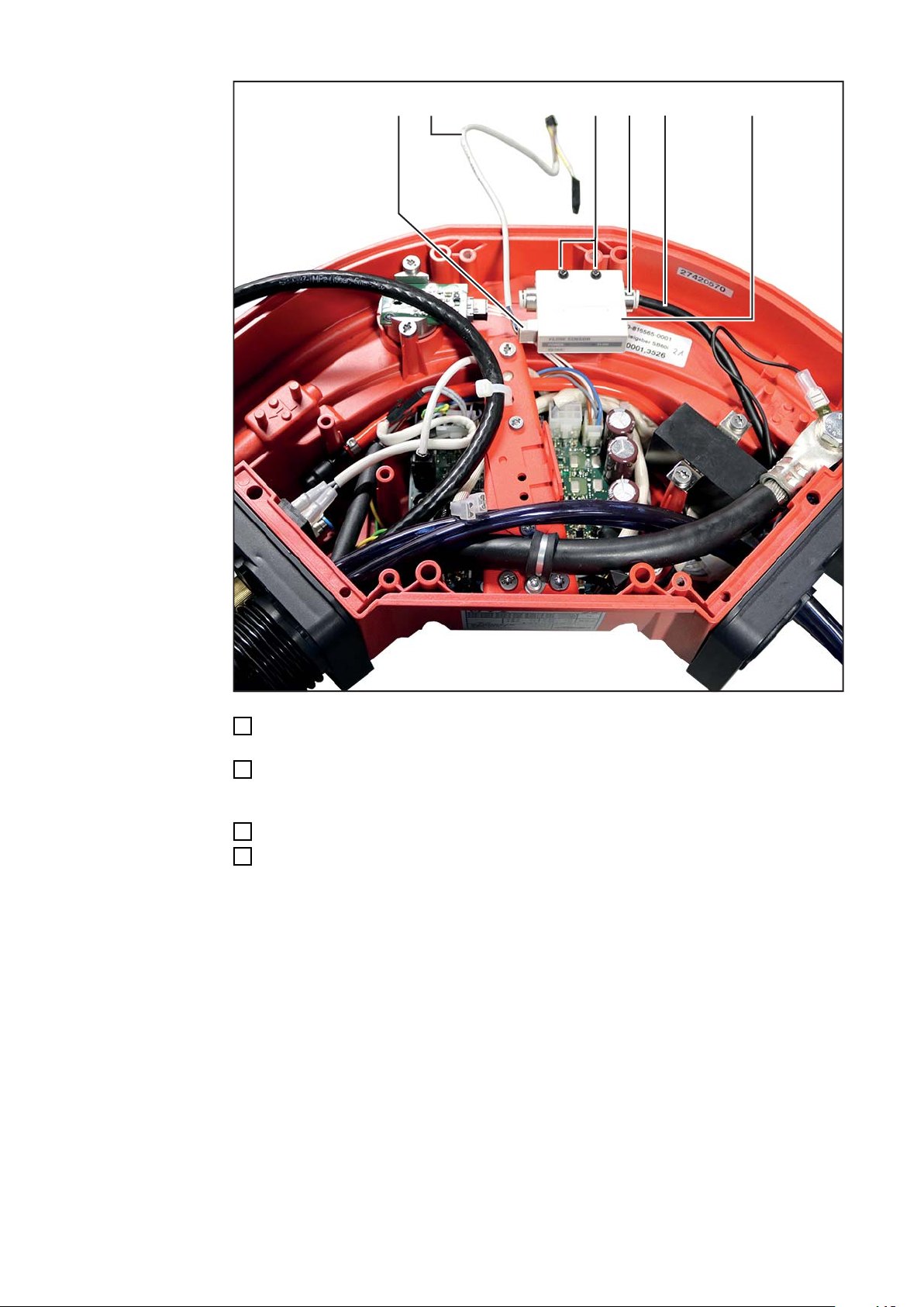
(14)(13)(12)(11) (8)
fluss-Sensor einbauen
WICHTIG! Beim Einsetzen des Sensors
darauf achten, dass der Pfeil zwischen IN
und OUT zum Zentralanschluss weist.
Sensor (8) mit 2 Schrauben M3 x 25
1
mm (7), 2 Scheiben (9) und 2 M3Sechskantmuttern (10) am Gehäuse
fixieren
SW 5,5, mm
Gasschlauch (5) beim Sensor (8) auf
2
Höhe der Sechskantmuttern ablängen,
Mittelstück entsorgen
Gasschlauch (11) vom Magnetventil
3
am Anschluss IN (12) am Sensor (8)
anstecken
Gasschlauch (14) vom Zentralan-
4
schluss am Anschluss OUT (13)
anstecken
24
(8)
(16)
(15)
(17)
X13
Kabel (17) am Sensor (8) und am
5
Print auf X13 anstecken
Kabel (17) mit 2 Kabelbindern (15)
6
und (16) fixieren
Kabelbinder ablängen
7
DE
Abschließende
Tätigkeiten
Abdeckung aufsetzen
1
Abdeckung mit 7 Schrauben TX25 festschrauben
2
Anzugsmoment = 3 Nm
Gerät am Roboter festschrauben
3
Verbindungen mit den anderen Systemkomponenten herstellen
4
25

Korrekturfaktoren der gängigsten Schutzgase
Gas Bezeich-
nung laut
He Ar CO
2
Luft O
H
2
Korrekturfak-
2
tor
DIN EN
439
Helium (He) M13 100% 11,821
Argon (Ar) I1 100% 1,720
Kohlendioxid (CO2) C1 100% 1,000
Luft 100% 1,525
Corgon 18 M21 82% 18% 1,523
Corgon 5 95% 5% 1,660
Corgon 8 92% 8% 1,626
Corgon 15 85% 15% 1,552
Corgon 20 80% 20% 1,503
Corgon 25 M21 75% 25% 1,458
Corgon He 25 C M21(1) 25% 50% 25% 1,780
M12 Ar+2%CO
2
M12 98% 2% 1,695
Cornigon 2 97,5% 2,5% 1,689
Varigon He 50 50% 50% 3,003
M13(1) Ar+He M13(1) 30% 70% 2,313
Cornigon He 20 M12(1) 20% 78% 2% 2,039
Arcal 121 Ar68He30CO222 M12(1) 30% 68% 2% 2,269
I3 Ar+15%He I3 15% 85% 1,973
I3 Ar+25%He I3 25% 75% 2,187
I3 Ar+30%He R2 30% 70% 2,313
Mixture M12(1) 20% 80% 2,074
Varigon He I3 90% 10% 7,447
C1 100% CO
2
100% 1,000
I1 100% Ar 100% 1,720
I3 Ar+30%He 30% 70% 2,313
I3 Ar+50%He 50% 50% 3,003
M12 Ar+20‑30%He+
2%CO
2
M12 Ar+2,5%CO
2
M12 Ar+30%He+0,5%CO
2
27,5
%
70,5% 2%
2,207
97,5% 2,5% 1,689
30% 69,5% 0,5% 2,302
M12 Ar+30%He+2%CO
M12 Ar+30%He+2,5%CO
M12 Ar+33%He+1%CO
26
2
2
2
30% 68% 2% 2,269
30% 67,5% 2,5% 2,258
33% 66% 1% 2,372

Gas Bezeich-
nung laut
DIN EN
439
He Ar CO
2
Luft O
H
2
Korrekturfak-
2
tor
DE
M12 Ar+90%He+2,5%CO
M13 Ar+2%O
M13 Ar+3%O
M13 Ar+2-5%O
M22 Ar+5%O
M12 Ar+2-5%O
M20Ar+10%CO
2
2
2
2
2
2
M20 Ar+26,5%He+7,5%CO
M20 Ar+5-10%CO
M20 Ar+8%CO
M20 Ar+8‑10%CO
M21 Ar+15-20%CO
M21 Ar+18%CO
M21 Ar+25%CO
2
2
2
2
2
2
2
90% 7,5% 2,5% 6,909
98% 2% 1,717
97% 3% 1,716
96,5%
3,5
%
1,715
(mit 3,5%O2)
95% 5% 1,713
96,5% 3,5%
1,678
(mit 3,5%O2)
90% 10% 1,604
2
26,5 66% 7,5% 2,078
92,5% 7,5% 1,632
92% 8% 1,626
91% 9%
1,615
(mit 9%CO2)
82% 18% 1,523
82% 18% 1,523
75% 25% 1,458
M31 Ar+50%CO
2
Z Ar+30%He+2%H2+
0,05%CO
2
Z Ar+50%He+
1 CO
2
50% 50% 1,265
30%
49% 50% 1%
67,95%0,05
%
2% 2,366
2,923
27

28

Table of contents
Scope of Supply 30
Scope of supply 30
Installing the OPT/i WF gas flow sensor into WF 15/25/30i 31
Safety 31
Preparatory work 32
Installing the OPT/i WF gas flow sensor into WF 15/25/30i 32
And finally... 35
Installing the OPT/i WF gas flow sensor into WF15/25/30i R and into SB 500i R 36
Safety 36
Preparation 37
Installation overview 37
Installing the OPT/i WF gas flow sensor into WF15/25/30i R and into SB 500i R 38
Final tasks 42
Installing the OPT/i WF gas flow sensor into SB 60i R 43
Safety 43
Preparations 43
Installation position 44
Installing the OPT/i WF gas flow sensor into SB 60i R 45
And finally... 48
Installing the OPT/i WF gas flow sensor into SB 360i LaserHybrid 49
Safety 49
Preparatory work 49
Installing the OPT/i gas flow sensor 50
And finally... 51
Correction factors for common shielding gases 52
EN-US
29

Scope of Supply
(1) (2)
(3)(4)(5)(6)(7)(10) (8)
(9)
(12)
(11)
Scope of supply
(1) Gas hose
(2) Cable for gas sensor
(3) Holding plate
(4) 4 x connection pieces
(5) Gas sensor
(6) 4 x TX 20 screws
(7) 2 x Allen screws
(8) 2 x Phillips-head screws
(9) 2 x TX 25 screws
(10) 2 x TX 10 screws
(11) 2 x hexagon nuts M3, 5.5 mm
(12) 2 x washers
30

Installing the OPT/i WF gas flow sensor into WF
15/25/30i
Safety
WARNING!
Danger from incorrect operation and work that is not carried out properly.
This can result in severe personal injury and damage to property.
All the work and functions described in this document must only be carried out by
▶
trained and qualified personnel.
Read and understand this document.
▶
Read and understand all the Operating Instructions for the system components,
▶
especially the safety rules.
WARNING!
Danger from electrical current.
Serious injuries or death may result.
Turn the mains switch of the power source to - O - and disconnect the power source
▶
from the mains
Secure all devices and components involved so they cannot be switched back on.
▶
After opening the device, use a suitable measuring instrument to check that electri-
▶
cally charged components (such as capacitors) have been discharged.
WARNING!
EN-US
Electrical current hazard caused by an inadequate ground conductor connection.
This can result in severe personal injury and damage to property.
Always use the original housing screws in the original quantity.
▶
CAUTION!
Risk of scalding from hot system components.
Before starting work allow all hot system components to cool down to room temperature
(+25°C, +77°F), for example:
coolant
▶
water-cooled system components
▶
wirefeeder drive motor
▶
31

Preparatory work
(1) (2)
(1)
Disconnect all connections on the
1
wire-feed unit from all other system
components
Take wirespool or basket-type spool
2
off the wire-feed unit
Place the wire-feed unit on a suitable
3
base
Undo two TX 25 screws (1)
4
Remove the right side panel (2)
5
Installing the
OPT/i WF gas
flow sensor into
WF 15/25/30i
Plug two connection pieces into each
1
other as shown (repeat for each set of
two pieces)
32

(6) (7)(10) (8)(10) (9)
Connect the prepared connection pieces (6) and (7) to the gas sensor (8) as shown
(11)
(4) (7)
2
Place the gas sensor (8) onto the holding plate (9) as shown and secure using the
3
two Allen screws (10)
- 2.5 mm
EN-US
Connect the existing gas hose (4) to the connection socket (7)
4
Plug the connector of the cable supplied into the connection socket (11) on the gas
5
sensor (8)
33

(8) (12)(12)
Insert the gas sensor (8) plus holding plate into the wirefeeder and secure using the
(13) (14)(6)
6
two TX25 screws (12)
- Tightening torque = 2.5 Nm
Connect the gas hose supplied (13) to connection sockets (6) and (14)
7
34
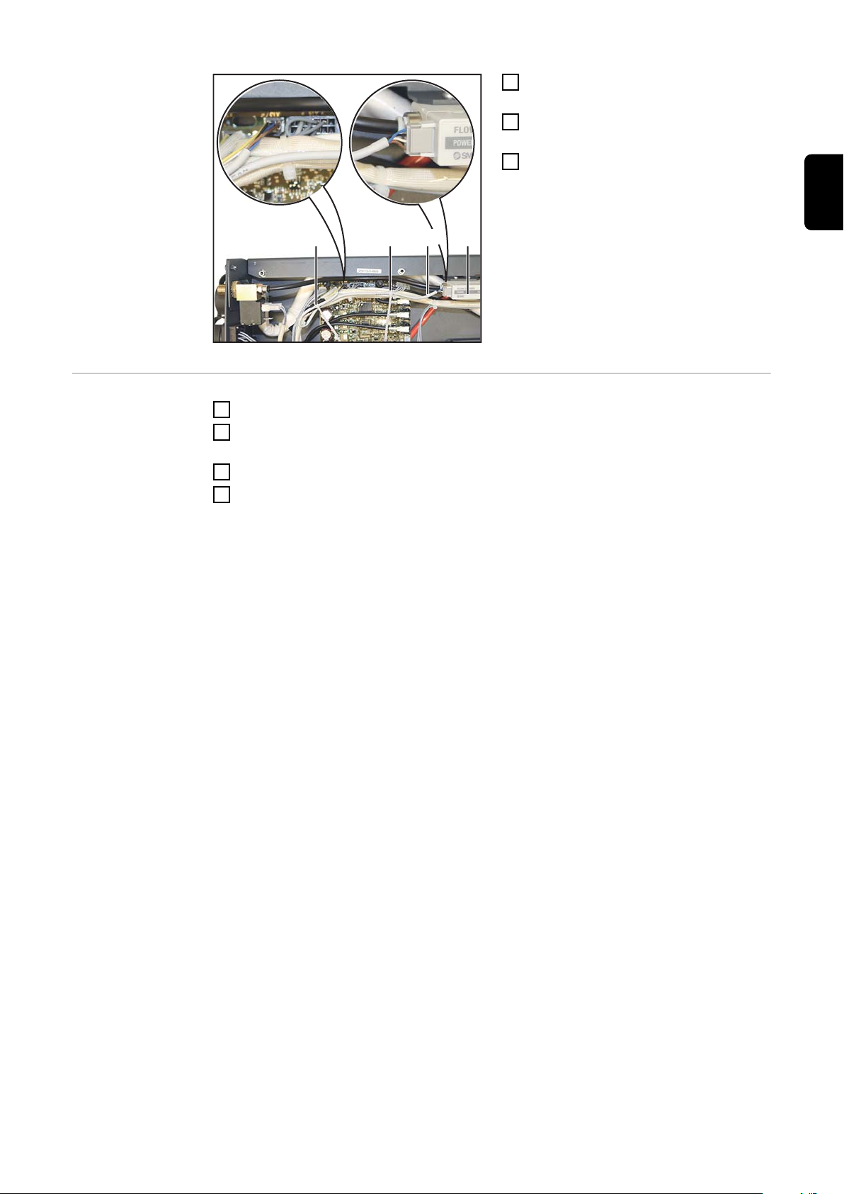
(15)
Plug the connector of the cable sup-
(1) (2)
(1)
8
plied (15) into the wirefeeder
- on PC board SR 63, socket X15
NOTE!
Plug in the connector (15) only as
shown in the enlarged view.
EN-US
And finally...
Fit the side panel (2)
1
Tighten two 5 x 14 mm screws (1)
2
using TX 25 screwdriver
- Tightening torque = 1.9 Nm
Return wire-feed unit to its original
3
position
Insert wirespool or basket-type spool
4
Restore connections to other system
5
components
35

Installing the OPT/i WF gas flow sensor into
WF15/25/30i R and into SB 500i R
Safety
WARNING!
Danger from incorrect operation and work that is not carried out properly.
This can result in severe personal injury and damage to property.
All the work and functions described in this document must only be carried out by
▶
trained and qualified personnel.
Read and understand this document.
▶
Read and understand all the Operating Instructions for the system components,
▶
especially the safety rules.
WARNING!
Danger from electrical current.
Serious injuries or death may result.
Turn the mains switch of the power source to - O - and disconnect the power source
▶
from the mains
Secure all devices and components involved so they cannot be switched back on.
▶
After opening the device, use a suitable measuring instrument to check that electri-
▶
cally charged components (such as capacitors) have been discharged.
WARNING!
Electrical current hazard caused by an inadequate ground conductor connection.
This can result in severe personal injury and damage to property.
Always use the original housing screws in the original quantity.
▶
CAUTION!
Risk of scalding from hot system components.
Before starting work allow all hot system components to cool down to room temperature
(+25°C, +77°F), for example:
coolant
▶
water-cooled system components
▶
wirefeeder drive motor
▶
36
Preparation
(1)
(1) (1)
(1)
(3)
(2)
Disconnect the device from all other system components
1
Place the device on a temporary backing
2
Remove 4 TX 20 screws (1)
3
Open the wirefeeder cover (2)
4
Remove the wirefeeder housing cover (3) from the unit as shown
5
EN-US
Installation overview
The OPT/i gas controller can be installed in the following devices:
- all variants of the WF 15/25/30i R robot wirefeeders
- all variants of the SB 500i R SplitBox
NOTE!
The procedure below describes the installation of an OPT/i gas controller on a WF
25i R.
The installation process is the same on all other compatible devices, however the locations of the relevant components and/or connection sockets may differ from model to
model. The main process steps are always the same:
Remove the gas solenoid valve installed in the device
1
Install the new gas solenoid valve
2
Install the gas sensor
3
Connect the OUT connection socket of the gas sensor to the motor plate using a gas
4
hose
Connect the IN connection socket of the gas sensor to the gas solenoid valve using
5
a gas hose
For more details on installation, see the following section.
Overview of correctly installed OPT/i gas controller:
37

Viewed from behind, gas solenoid valve on left (left
device variant)
Viewed from behind, gas solenoid valve on right
(right device variant)
Installing the
OPT/i WF gas
flow sensor into
WF15/25/30i R
and into SB 500i
R
NOTE!
The connection pieces are not always
necessary on every device.
To check whether the connection pieces
are necessary, it is advised to place the
gas sensor (8) plus holding plate (10) in
the later installation position and clarify the
routing of the gas hoses.
Plug the two connection pieces into
1
each other as shown
38

(9)(7)
(11) (11) (10)(8)
If necessary: connect the prepared connection pieces (7) to the gas sensor (8) as
(12) (8)(12) (12)(12)
2
shown
If necessary: connect the connection piece (9) to the gas sensor (8)
3
Place the gas sensor (8) onto the holding plate (10) as shown and secure using the
4
two Phillips-head screws (11)
EN-US
Insert the gas sensor (8) plus holding plate into the wirefeeder and secure using the
5
four TX20 screws (12)
- Tightening torque = 2.5 Nm
39

IN
OUT
The gas sensor (8) must always be connected to the gas solenoid valve / motor plate
(15) (4) (13)(14)(7)
using gas hoses (4) and (13) as described below
- Gas sensor connection socket IN -> Gas solenoid valve (5)
- Gas sensor connection socket OUT -> Motor plate
- For more information, see "Installation overview" at the start of the section "Installing
the OPT/i gas controller: all variants of the WF15/25/30i R robot wirefeeders, all variants of the SB 500i R SplitBox"
40
Connect the existing gas hose (4) to connection socket (7)
6
Connect the gas hose supplied (13) to connection sockets (14) and (15)
7

(16) (8)
Plug the connector (16) of the cable supplied into the wirefeeder (8)
(17)
8
EN-US
Plug the six-pin connector of the cable supplied into the device
9
- on PC board SR63, socket X15 (17)
NOTE!
Plug in the six-pin connector of the cable supplied only as shown in the enlarged
view.
41

Final tasks
(3)
(2)
(1)
(1) (1)
(1)
NOTE!
When installing the wirefeeder housing cover, make sure that the cables and
hoses are not kinked, pinched, abraded or otherwise damaged.
Push the wirefeeder housing cover (3) onto the device as far as it will go
1
Tighten 4 TX 20 screws (1)
2
Close the wirefeeder cover (2)
3
Move the device to its home position
4
Connect to other system components
5
42

Installing the OPT/i WF gas flow sensor into SB 60i
R
Safety
WARNING!
Danger from incorrect operation and work that is not carried out properly.
This can result in severe personal injury and damage to property.
All the work and functions described in this document must only be carried out by
▶
trained and qualified personnel.
Read and understand this document.
▶
Read and understand all the Operating Instructions for the system components,
▶
especially the safety rules.
WARNING!
Danger from electrical current.
Serious injuries or death may result.
Turn the mains switch of the power source to - O - and disconnect the power source
▶
from the mains
Secure all devices and components involved so they cannot be switched back on.
▶
After opening the device, use a suitable measuring instrument to check that electri-
▶
cally charged components (such as capacitors) have been discharged.
WARNING!
EN-US
Preparations
Electrical current hazard caused by an inadequate ground conductor connection.
This can result in severe personal injury and damage to property.
Always use the original housing screws in the original quantity.
▶
CAUTION!
Risk of scalding from hot system components.
Before starting work allow all hot system components to cool down to room temperature
(+25°C, +77°F), for example:
coolant
▶
water-cooled system components
▶
wirefeeder drive motor
▶
Disconnect all connections on the device from all other system components
1
Remove the device from the robot
2
Place the device on a suitable base with the transparent cover facing down
3
43
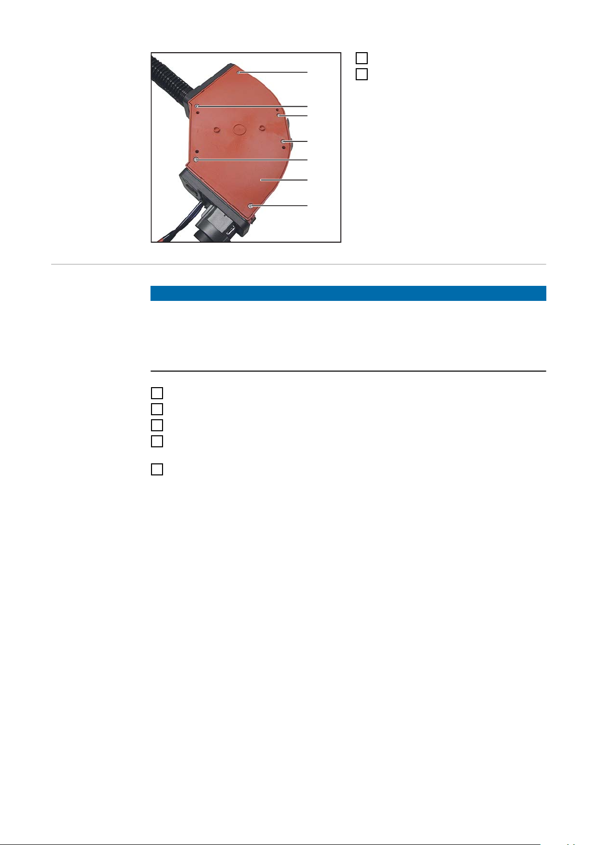
(1)
(2)
(1)
(1)
(1)
(1)
Undo the six TX 25 screws (1)
4
Remove cover (2)
5
Installation position
NOTE!
The installation below is illustrated based on the right-hand version of the SB 60i
R.
The installation process for the left-hand version of the SB 60i R is the same, however
the relevant components/connections are in different positions. The main process steps
are always the same:
Remove the gas solenoid valve installed in the device
1
Install the new gas solenoid valve
2
Install the gas sensor
3
Connect the IN connection socket of the gas sensor to the gas solenoid valve using
4
a gas hose
Connect the OUT connection socket of the gas sensor to the welding torch connec-
5
tion (FSC) using a gas hose
For more details on installation, see the following section.
44

Installing the
IN
OUT
OPT/i WF gas
flow sensor into
SB 60i R
EN-US
The gas sensor (6) must always be connected to the gas solenoid valve / welding torch
connection (FSC) using gas hoses as described below
- Gas sensor connection socket IN -> Gas solenoid valve (11)
- Gas sensor connection socket OUT -> Welding torch connection (FSC)
- For more information see "Installation overview" at the start of the section "Installing
the OPT/i gas controller: SB 60i R"
45

(1)(8)(9)(10) (6)(7)
Insert the gas sensor (6) into the device as shown and secure using the two TX 10
1
screws (7) supplied
Cut the gas hose (1) so that it can be connected to the OUT connection socket (8) of
2
the gas sensor (6) as shown. Retain the cut-off part of the gas hose
Connect the gas hose (1) to the connection socket (8) on the gas sensor (6)
3
Connect the cable supplied (9) to the socket (10) on the gas sensor (6)
4
46

(9) (6)
(11)
Plug the six-pin connector of the cable (9) supplied into the device
5
- on PC board SR63, socket X15 (11)
EN-US
NOTE!
Plug in the six-pin connector of the cable supplied only as shown in the enlarged
view.
47

(1) (14) (6)
Connect the gas hose (1) to the IN connection socket (14) of the gas sensor (6)
(1)
(2)
(1)
(1)
(1)
(1)
6
And finally...
Fit the cover (2)
1
Secure the cover with six TX25
2
screws (1)
Tightening torque = 3 Nm
Screw the device to the robot (4 x Allen screws M6 x 60 mm)
3
Establish connections to the other system components
4
48

Installing the OPT/i WF gas flow sensor into SB
360i LaserHybrid
Safety
WARNING!
Danger from incorrect operation and work that is not carried out properly.
This can result in severe personal injury and damage to property.
All the work and functions described in this document must only be carried out by
▶
trained and qualified personnel.
Read and understand this document.
▶
Read and understand all the Operating Instructions for the system components,
▶
especially the safety rules.
WARNING!
Danger from electrical current.
Serious injuries or death may result.
Turn the mains switch of the power source to - O - and disconnect the power source
▶
from the mains
Secure all devices and components involved so they cannot be switched back on.
▶
After opening the device, use a suitable measuring instrument to check that electri-
▶
cally charged components (such as capacitors) have been discharged.
WARNING!
EN-US
Preparatory work
Electrical current hazard caused by an inadequate ground conductor connection.
This can result in severe personal injury and damage to property.
Always use the original housing screws in the original quantity.
▶
CAUTION!
Risk of scalding from hot system components.
Before starting work allow all hot system components to cool down to room temperature
(+25°C, +77°F), for example:
coolant
▶
water-cooled system components
▶
wirefeeder drive motor
▶
Disconnect all connections on the device from all other system components
1
Remove the device from the robot
2
Remove seven TX25 screws
3
Remove the cover
4
49

Installing the
(7)
(7)
(8)
(9) (10)
(9)
(10)
(8)
(5)
(14)(13)(12)(11) (8)
OPT/i gas flow
sensor
IMPORTANT! When inserting the sensor,
ensure that the arrow between IN and
OUT is pointing towards the central connector.
Secure the sensor (8) to the housing
1
using two M3 x 25 mm screws (7), two
washers (9) and two M3 hexagon nuts
(10)
Size 5.5 mm
Cut the gas hose (5) at the hexagon
2
nuts on the sensor (8), dispose of the
middle piece
Connect the gas hose (11) from the
3
solenoid valve to the IN connection
socket (12) on the sensor (8)
Connect the gas hose (14) from the
4
central connector to the OUT connection socket (13)
50
(8)
(16)
(15)
(17)
X13
Connect the cable (17) to the sensor
5
(8) and X13 on the PC board
Fix cable (17) in place with two cable
6
ties (15) and (16)
Trim the cable ties as required
7
EN-US
And finally...
Replace the cover
1
Secure the cover with seven TX25 screws
2
Tightening torque = 3 Nm
Secure the device to the robot
3
Establish connections to the other system components
4
51

Correction factors for common shielding gases
Gas Designa-
tion as per
He Ar CO
2
Air O
H2Correction fac-
2
tor
DIN EN
439
Helium (He) M13 100% 11.821
Argon (Ar) I1 100% 1.720
Carbon dioxide (CO2) C1 100% 1.000
Air 100% 1.525
Corgon 18 M21 82% 18% 1.523
Corgon 5 95% 5% 1.660
Corgon 8 92% 8% 1.626
Corgon 15 85% 15% 1.552
Corgon 20 80% 20% 1.503
Corgon 25 M21 75% 25% 1.458
Corgon He 25 C M21(1) 25% 50% 25% 1.780
M12 Ar+2%CO
2
M12 98% 2% 1.695
Cornigon 2 97.5% 2.5% 1.689
Varigon He 50 50% 50% 3.003
M13(1) Ar+He M13(1) 30% 70% 2.313
Cornigon He 20 M12(1) 20% 78% 2% 2.039
Arcal 121 Ar68He30CO222 M12(1) 30% 68% 2% 2.269
I3 Ar+15%He I3 15% 85% 1.973
I3 Ar+25%He I3 25% 75% 2.187
I3 Ar+30%He R2 30% 70% 2.313
Mixture M12(1) 20% 80% 2.074
Varigon He I3 90% 10% 7.447
C1 100% CO
2
100% 1.000
I1 100% Ar 100% 1.720
I3 Ar+30%He 30% 70% 2.313
I3 Ar+50%He 50% 50% 3.003
M12 Ar+20‑30%He+
2%CO
2
M12 Ar+2.5%CO
2
M12 Ar+30%He+0.5%CO
2
27.5
%
70.5% 2%
2.207
97.5% 2.5% 1.689
30% 69.5% 0.5% 2.302
M12 Ar+30%He+2%CO
M12 Ar+30%He+2.5%CO
M12 Ar+33%He+1%CO
52
2
2
2
30% 68% 2% 2.269
30% 67.5% 2.5% 2.258
33% 66% 1% 2.372

Gas Designa-
tion as per
DIN EN
439
He Ar CO
2
Air O
H2Correction fac-
2
tor
M12 Ar+90%He+2.5%CO
M13 Ar+2%O
M13 Ar+3%O
M13 Ar+2-5%O
M22 Ar+5%O
M12 Ar+2-5%O
M20Ar+10%CO
2
2
2
2
2
2
M20 Ar+26.5%He+7.5%CO
M20 Ar+5-10%CO
M20 Ar+8%CO
M20 Ar+8‑10%CO
M21 Ar+15-20%CO
M21 Ar+18%CO
M21 Ar+25%CO
2
2
2
2
2
2
2
90% 7.5% 2.5% 6.909
98% 2% 1.717
97% 3% 1.716
96.5%
3.5
%
1.715
(with 3.5%O2)
EN-US
95% 5% 1.713
96.5% 3.5%
1.678
(with 3.5%O2)
90% 10% 1.604
2
26.5 66% 7.5% 2.078
92.5% 7.5% 1.632
92% 8% 1.626
91% 9%
1.615
(with 9%CO2)
82% 18% 1.523
82% 18% 1.523
75% 25% 1.458
M31 Ar+50%CO
2
Z Ar+30%He+2%H2+
0.05%CO
2
Z Ar+50%He+
1 CO
2
50% 50% 1.265
30%
49% 50% 1%
67.95%0.05
%
2% 2.366
2.923
53

54

EN-US
55

FRONIUS INTERNATIONAL GMBH
Froniusstraße 1
A-4643 Pettenbach
AUSTRIA
contact@fronius.com
www.fronius.com
Under www.fronius.com/contact you will find the addresses
of all Fronius Sales & Service Partners and locations
 Loading...