


Fronius prints on elemental chlorine free paper (ECF) sourced from certified sustainable forests (FSC).
/ Perfect Charging / Perfect Welding / Solar Energy
OPT/i WF ext. Startsignal
OPT/i WF ext. start signal
Signal de démarrage ext. OPT/i WF
Installationsanleitung
DE
Systemerweiterung
Installation instructions
EN
System upgrade
Instructions d'installation
FR
Extension de système
42,0410,1964 010-10092021


Inhaltsverzeichnis
Allgemeines 4
Lieferumfang 4
Vorgaben für den Roboter-Ausgang 4
WF 15/25/30i: OPT/i WF ext. Startsignal einbauen 5
Sicherheit 5
Vorbereitungen 6
OPT/i WF ext. Startsignal einbauen 6
Abschließende Tätigkeiten 10
WF 25i Case (D300): OPT/i WF ext. Startsignal einbauen 11
Sicherheit 11
Vorbereitungen 11
OPT/i WF ext. Startsignal einbauen 12
Abschließende Tätigkeiten 15
DE
3
Allgemeines
(2)
(3)
(4)
(5)
(6)
(7)
(1)
Lieferumfang
Vorgaben für den
Roboter-Ausgang
(1) Anschluss-Stecker
(2) Steckereinfassung mit Blindstecker
(3) 2 x Mutter M4
(4) 2 x Scheibe M4
(5) 2 x Fächerscheibe M4
(6) 2 x Schrauben (2,9 mm x 16 mm)
(7) Kabelbaum mit Sockel
nicht abgebildet:
- dieses Dokument
VORSICHT!
Gefahr durch fehlerhaft durchgeführte Arbeiten.
Sachschäden am Drahtvorschub durch Überspannung können die Folge sein.
Der Roboter-Ausgang für die Option „OPT/i ext. Startsignal“ muss ein potentialfreier
▶
Ausgang sein.
4

WF 15/25/30i: OPT/i WF ext. Startsignal einbauen
DE
Sicherheit
WARNUNG!
Gefahr durch Fehlbedienung und fehlerhaft durchgeführte Arbeiten.
Schwerwiegende Personen- und Sachschäden können die Folge sein.
Alle in diesem Dokument beschriebenen Arbeiten und Funktionen dürfen nur von
▶
geschultem Fachpersonal ausgeführt werden.
Dieses Dokument lesen und verstehen.
▶
Sämtliche Bedienungsanleitungen der Systemkomponenten, insbesondere Sicher-
▶
heitsvorschriften lesen und verstehen.
WARNUNG!
Gefahr durch elektrischen Strom.
Schwerwiegende Personen- und Sachschäden können die Folge sein.
Netzschalter der Stromquelle in Stellung - O - schalten und die Stromquelle vom
▶
Netz trennen
Alle beteiligten Geräte und Komponenten gegen Wiedereinschalten sichern.
▶
Nach dem Öffnen des Gerätes mit Hilfe eines geeigneten Messgerätes sicherstel-
▶
len, dass elektrisch geladene Bauteile (beispielsweise Kondensatoren) entladen
sind.
WARNUNG!
Gefahr durch elektrischen Strom wegen unzureichender Schutzleiter-Verbindung.
Schwerwiegende Personen- und Sachschäden können die Folge sein.
Immer die originalen Gehäuse-Schrauben in der ursprünglichen Anzahl verwenden.
▶
VORSICHT!
Verletzungsgefahr durch heiße Systemkomponenten.
Schwere Verbrühungen können die Folge sein.
Vor Beginn der Arbeiten alle heißen Systemkomponenten auf Zimmertemperatur
▶
(+25 °C, +77 °F) abkühlen lassen, beispielsweise: Kühlmittel, wassergekühlte Systemkomponenten, Antriebsmotor des Drahtvorschubes
5
Vorbereitungen
(1) (2)
(1)
(1)
(2)
Sämtliche Verbindungen des Draht-
1
vorschubes von allen anderen Systemkomponenten trennen
Draht- oder Korbspule dem Drahtvor-
2
schub entnehmen
Drahtvorschub auf einer geeigneten
3
Unterlage ablegen
2 Schrauben TX 25 (1) lösen
4
Seitenteil rechts (2) entfernen
5
OPT/i WF ext.
Startsignal einbauen
Blindabdeckung (1) entfernen
1
Steckereinfassung (2) wie abgebildet
2
einsetzen
6
(7)
(6)
(5)
(7)
(6)
(5)
(3)
(4)
Den Bereich (3) links und rechts im
(9)
(9)
(8)
(10)
(11)
3
Gehäuse des Drahtvorschubes so
weit ausfeilen, bis die Bohrungen (4)
der Steckereinfassung (2) nicht mehr
vom Gehäuse des Drahtvorschubes
verdeckt werden
Steckereinfassung (2) wie abgebildet
4
mit den mitgelieferten Scheiben (5),
Fächerscheiben (6) und Muttern (7)
festschrauben
Kabelbaum des Sockels (8) durch die
5
Steckereinfassung (2) in den
Geräteinnenraum führen
Den Sockel (8) so einsetzen, dass
6
sich die beiden Kontakte (10) links
befinden - von der Rückseite des
Drahtvorschubes aus betrachtet
Sockel (8) mit den mitgelieferten
7
Schrauben 2,9 mm x 16 mm (9) festschrauben
DE
Stecker X14 (11) vom Print SR63 im
8
Drahtvorschub abstecken
7

(11)
(12)(13)
1 2 3 4 5 6
12
Kabel (12) und (13) vom Sockel (8)
(14)
(11)
(16)(18) (17) (16)
(18)
(19)
9
gemäß deren Beschriftung am Stecker
X14 (11) anschließen
- X14:6 Signal ‘Gun Trigger‘
- X14:12 Signal ‘GND‘
Stecker X14 (11) an der ursprüngli-
10
chen Position am Print SR63 anstecken
Kabelbaum (14) vom Sockel (8) wie
11
abgebildet verlegen
Schrauben (16) des mitgelieferten
12
Anschluss-Steckers lösen und Steckereinsatz (17) dem Steckergehäuse
entnehmen
Schraube (18) lösen und Zugentlas-
13
tung (19) dem Steckergehäuse entnehmen
8

7
8
9
5
4
3
2
1
6
(20)
(17)
Kabel (20) der kundenseitigen Steue-
(16)
(17)
(16)
(18)
(19)
(18)
(8)
(15)
14
rung durch das Steckergehäuse
durchführen
Die Drähte des Kabels (20) am Pin 9
15
und 5 des Steckereinsatzes (17)
anlöten (siehe auch Schaltplan des
Drahtvorschubes)
Steckereinsatz (17) in das Stecker-
16
gehäuse einsetzen und mit zwei
Schrauben (16) festschrauben
Zugentlastung (19) in das Stecker-
17
gehäuse einsetzen und mittels
Schraube (18) festschrauben
Den Anschluss-Stecker an Sockel (8)
18
anschließen
DE
VORSICHT!
Gefahr durch fehlerhaft durchgeführte
Arbeiten.
Sachschäden am Drahtvorschub durch
Überspannung können die Folge sein.
Der Roboter-Ausgang für die Option
▶
„OPT/i ext. Startsignal“ muss ein
potentialfreier Ausgang sein.
HINWEIS!
Falls der mitgelieferte Anschluss-Stecker nicht an den Sockel (8) angeschlossen wird, den Blindstecker (15)
auf den Sockel (8) stecken - nur
dadurch wird der IP-Schutzgrad des
Gerätes erreicht.
9
Abschließende
(1) (2)
(1)
Tätigkeiten
Seitenteil (2) einsetzen
1
2 Schrauben 5 x 14 mm (1) mittels
2
Schraubendreher TX 25 festschrauben
- Anzugsmoment = 1,9 Nm
Drahtvorschub wieder in seine Aus-
3
gangsposition bringen
Draht- oder Korbspule einsetzen
4
Verbindungen mit anderen System-
5
komponenten wieder herstellen
10

WF 25i Case (D300): OPT/i WF ext. Startsignal einbauen
Sicherheit
WARNUNG!
Gefahr durch Fehlbedienung und fehlerhaft durchgeführte Arbeiten.
Schwerwiegende Personen- und Sachschäden können die Folge sein.
Alle in diesem Dokument beschriebenen Arbeiten und Funktionen dürfen nur von
▶
geschultem Fachpersonal ausgeführt werden.
Dieses Dokument lesen und verstehen.
▶
Sämtliche Bedienungsanleitungen der Systemkomponenten, insbesondere Sicher-
▶
heitsvorschriften lesen und verstehen.
WARNUNG!
Gefahr durch elektrischen Strom.
Schwerwiegende Personen- und Sachschäden können die Folge sein.
Netzschalter der Stromquelle in Stellung - O - schalten und die Stromquelle vom
▶
Netz trennen
Alle beteiligten Geräte und Komponenten gegen Wiedereinschalten sichern.
▶
Nach dem Öffnen des Gerätes mit Hilfe eines geeigneten Messgerätes sicherstel-
▶
len, dass elektrisch geladene Bauteile (beispielsweise Kondensatoren) entladen
sind.
DE
Vorbereitungen
WARNUNG!
Gefahr durch elektrischen Strom wegen unzureichender Schutzleiter-Verbindung.
Schwerwiegende Personen- und Sachschäden können die Folge sein.
Immer die originalen Gehäuse-Schrauben in der ursprünglichen Anzahl verwenden.
▶
VORSICHT!
Verletzungsgefahr durch heiße Systemkomponenten.
Schwere Verbrühungen können die Folge sein.
Vor Beginn der Arbeiten alle heißen Systemkomponenten auf Zimmertemperatur
▶
(+25 °C, +77 °F) abkühlen lassen, beispielsweise: Kühlmittel, wassergekühlte Systemkomponenten, Antriebsmotor des Drahtvorschubes
Sämtliche Verbindungen des Drahtvorschubes von allen anderen Systemkomponen-
1
ten trennen
Draht- oder Korbspule dem Drahtvorschub entnehmen
2
Drahtvorschub auf einer geeigneten Unterlage ablegen
3
11
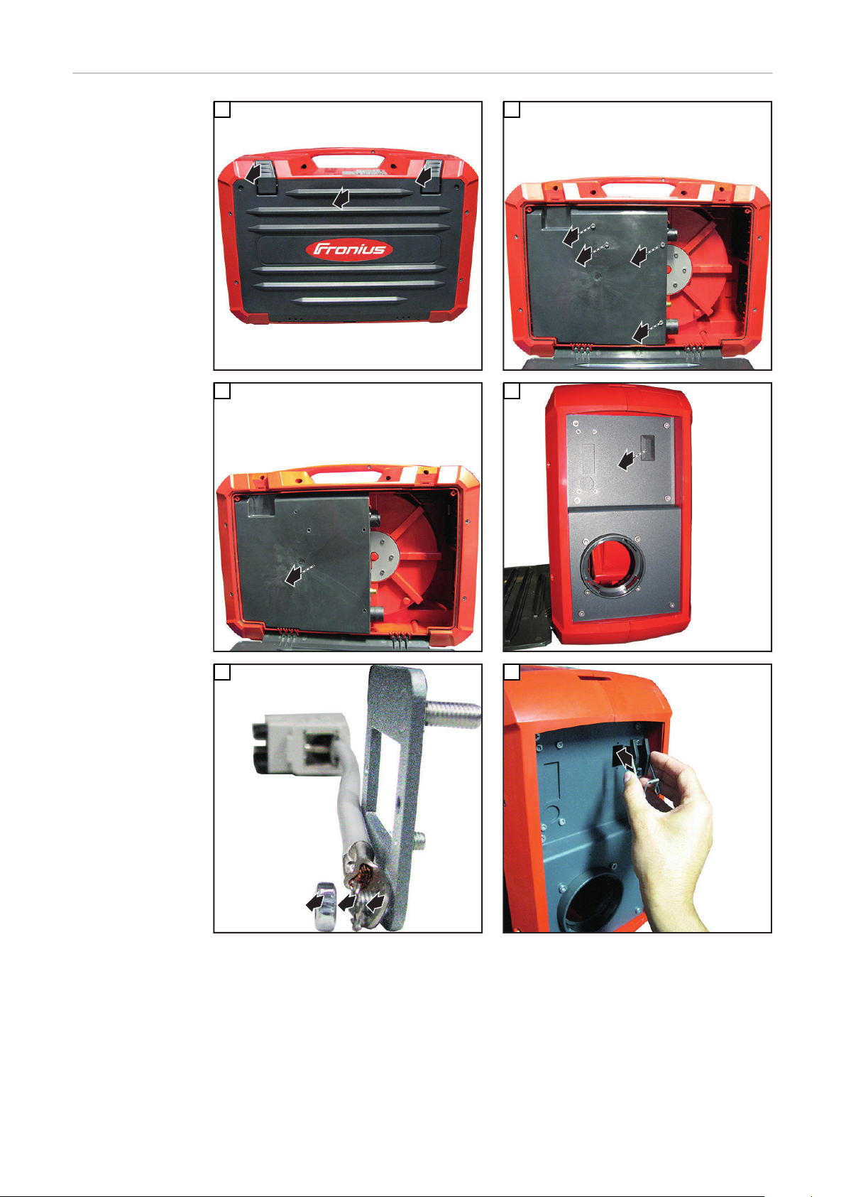
OPT/i WF ext.
2
1
3
1
2
3
4
1
1
1
2
3
1
Startsignal einbauen
1
2
3
5
4
6
12
1
7
1
2
1
X14
1
(1) (2)
1 2 3 4 5 6
12
(3)
(4)
8
DE
9
10
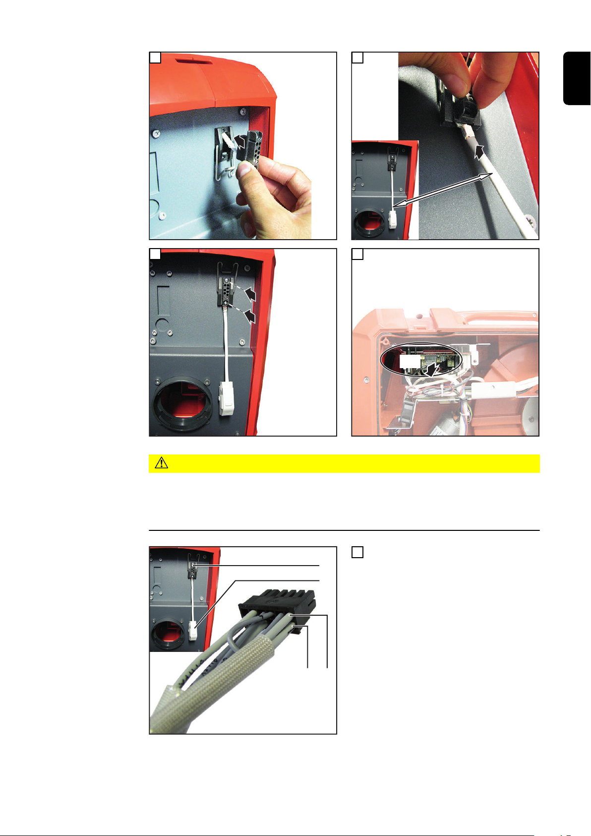
VORSICHT!
Gefahr durch fehlerhaft durchgeführte Arbeiten.
Sachschäden am Drahtvorschub durch Überspannung können die Folge sein.
Der Roboter-Ausgang für die Option „OPT/i ext. Startsignal“ muss ein potentialfreier
▶
Ausgang sein.
Kabel (1) und (2) vom Sockel (3)
11
gemäß deren Beschriftung am Stecker
X14 (11) anschließen
- X14:6 Signal ‘Gun Trigger‘
- X14:12 Signal ‘GND‘
13

X14
1
12
1
2
1
2
3
4
5
1
2
3
(5)(7) (6) (5)
(7)
(8)
13
14
15
Schrauben (5) des mitgelieferten
16
Anschluss-Steckers lösen und Steckereinsatz (6) dem Steckergehäuse
entnehmen
Schraube (7) lösen und Zugentlastung
17
(8) dem Steckergehäuse entnehmen
14

7
8
9
5
4
3
2
1
6
(9)
(6)
Kabel (9) der kundenseitigen Steue-
(8)
(7)
(5)
(6)
(5)
(7)
18
rung durch das Steckergehäuse
durchführen
Die Drähte des Kabels (9) am Pin 9
19
und 5 des Steckereinsatzes (6)
anlöten (siehe auch Schaltplan des
Drahtvorschubes)
Steckereinsatz (6) in das Stecker-
20
gehäuse einsetzen und mit zwei
Schrauben (5) festschrauben
Zugentlastung (8) in das Stecker-
21
gehäuse einsetzen und mittels
Schraube (7) festschrauben
Den Anschluss-Stecker an Sockel (3)
22
anschließen
DE
Abschließende
Tätigkeiten
HINWEIS!
Falls der mitgelieferte Anschluss-Stecker nicht an den Sockel (3) angeschlossen wird, den Blindstecker (4)
auf den Sockel (3) stecken - nur
dadurch wird der IP-Schutzgrad des
Gerätes erreicht.
Drahtvorschub wieder in seine Ausgangsposition bringen
1
Draht- oder Korbspule einsetzen
2
Verbindungen mit anderen Systemkomponenten wieder herstellen
3
15

16

Contents
General 18
Scope of supply 18
Specifications for the robot output 18
WF 15/25/30i: Installing the OPT/i WF ext. start signal 19
Safety 19
Preparatory work 20
Installing the OPT/i WF ext. start signal 20
And finally... 24
WF 25i Case (D300): Installing the OPT/i WF ext. start signal 25
Safety 25
Preparations 25
Installing the OPT/i WF ext. start signal 26
And finally... 29
EN
17

General
(2)
(3)
(4)
(5)
(6)
(7)
(1)
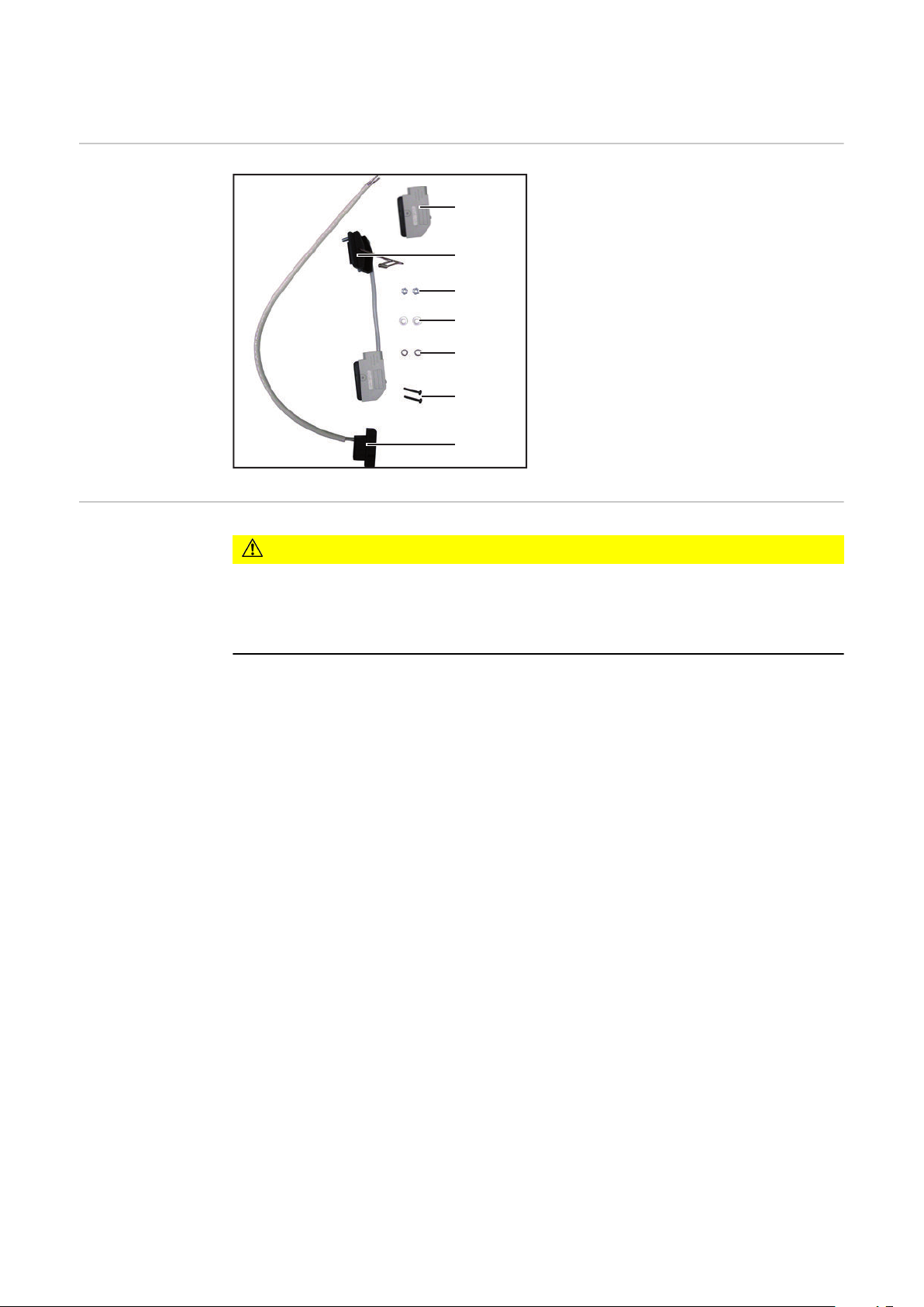
Scope of supply
Specifications for
the robot output
(1) Connecting plug
(2) Connector receptacle with dummy
connector
(3) 2 x M4 nuts
(4) 2 x M4 washers
(5) 2 x M4 serrated washers
(6) 2 x screws (2.9 mm x 16 mm)
(7) Cable harness with socket
Not shown:
- this document
CAUTION!
Danger due to work that has been carried out incorrectly.
This can result in damage to the wire-feed unit through overvoltage.
The robot output for the "OPT/i ext. start signal" option must be a floating output.
▶
18

WF 15/25/30i: Installing the OPT/i WF ext. start
signal
Safety
WARNING!
Danger due to incorrect operation and incorrectly performed work.
This can result in serious injury and damage to property.
All the work and functions described in this document must only be carried out by
▶
trained and qualified personnel.
Read and understand this document.
▶
Read and understand all the Operating Instructions for the system components,
▶
especially the safety rules.
WARNING!
Electrical current hazard.
This can result in serious injury and damage to property.
Turn the mains switch of the power source to the "O" position and disconnect the
▶
power source from the mains supply.
Secure all the devices and components involved to prevent unintentional restarting.
▶
After opening the device, use a suitable measuring instrument to check that electri-
▶
cally charged components (such as capacitors) have been discharged.
WARNING!
EN
Electrical current hazard caused by an inadequate ground conductor connection.
This can result in serious injury and damage to property.
Always use the original housing screws in the original quantity.
▶
CAUTION!
Risk of scalding from hot system components.
This can result in severe scalds.
Before starting work, allow all hot system components to cool down to room tempe-
▶
rature (+25 °C, +77 °F). For example: Coolant, water-cooled system components,
wirefeeder drive motor.
19

Preparatory work
(1) (2)
(1)
(1)
(2)
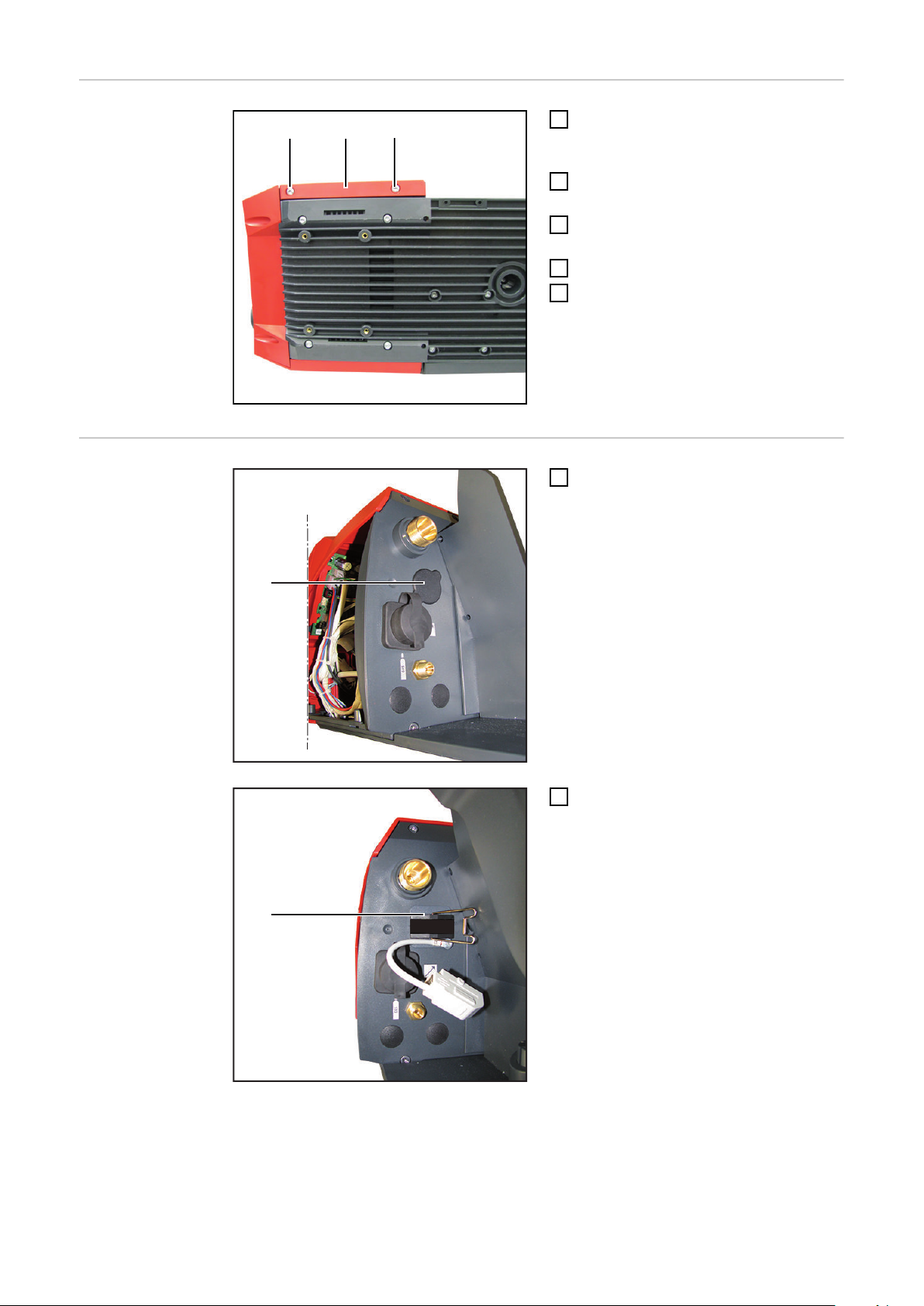
Disconnect all connections on the
1
wire-feed unit from all other system
components
Take wirespool or basket-type spool
2
off the wire-feed unit
Place the wire-feed unit on a suitable
3
base
Undo two TX 25 screws (1)
4
Remove the right side panel (2)
5
Installing the
OPT/i WF ext.
start signal
Remove the blanking cover (1)
1
Fit the connector receptacle (2) as
2
shown
20

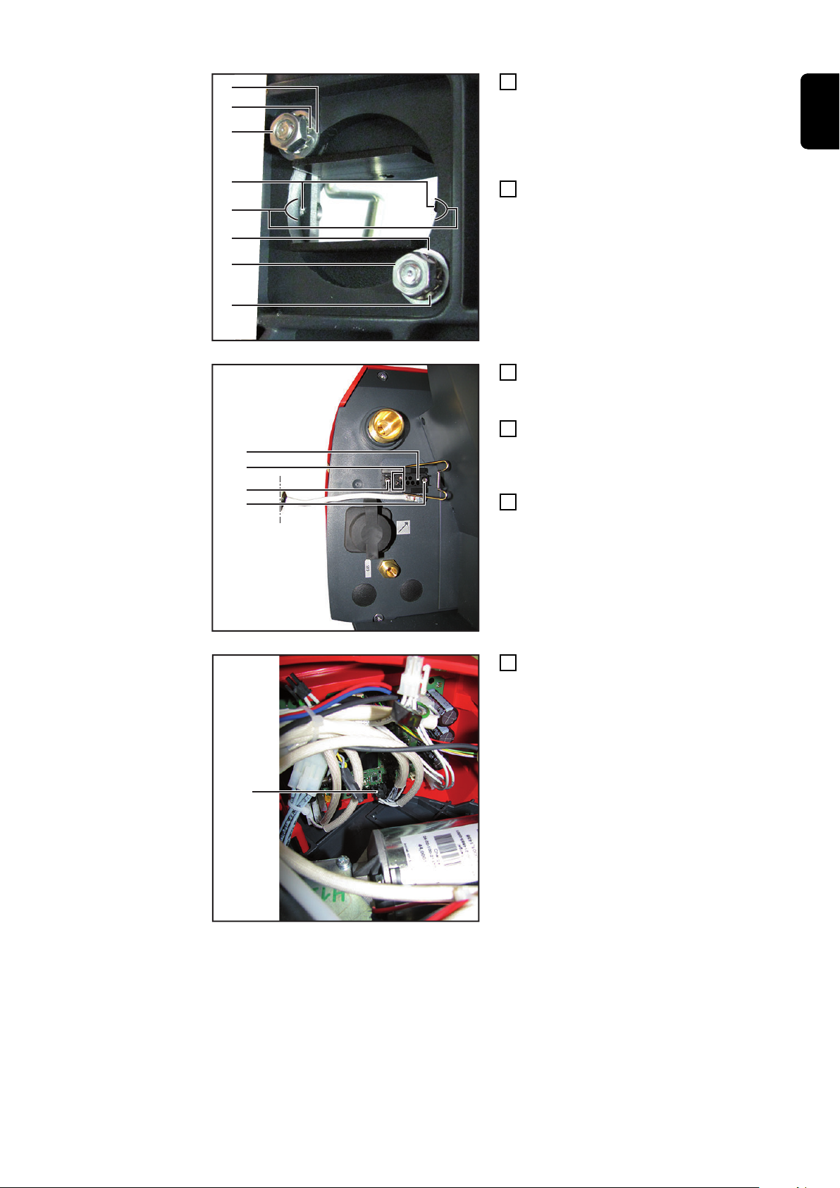
(7)
(6)
(5)
(7)
(6)
(5)
(3)
(4)
File the area (3) to the left and right in
(9)
(9)
(8)
(10)
(11)
3
the wire-feed unit housing until the
holes (4) of the connector receptacle
(2) are no longer concealed by the
wire feed unit housing
Fasten the connector receptacle (2)
4
using the washers (5), serrated washers (6) and nuts (7) supplied as
shown
Feed the cable harness of the socket
5
(8) through the connector receptacle
(2) into the device
Position the socket (8) so that both
6
contacts (10) are on the left when
viewed from the rear of the wire-feed
unit
Fasten the socket (8) using the 2.9 x
7
16 mm screws (9) provided
EN
Unplug the X14 plug (11) from the
8
SR63 PC board in the wire-feed unit
21

(11)
(12)(13)
1 2 3 4 5 6
12
Connect the cables (12) and (13) from
(14)
(11)
(16)(18) (17) (16)
(18)
(19)
9
the socket (8) to the X14 plug (11) as
indicated
- X14:6 'Gun Trigger' signal
- X14:12 'GND' signal
Connect the X14 plug (11) into the ori-
10
ginal position on the SR63 PC board
Route the cable harness (14) from the
11
socket (8) as shown
Undo the screws (16) of the connec-
12
ting plug provided and remove the
plug insert (17) from the plug housing
Undo the screw (18) and remove the
13
strain-relief device (19) from the plug
housing
22

7
8
9
5
4
3
2
1
6
(20)
(17)
Guide the cable (20) of the customer-
(16)
(17)
(16)
(18)
(19)
(18)
(8)
(15)
14
provided controller through the plug
housing
Solder the wires of the cable (20) on
15
pin 9 and 5 of the plug insert (17) (see
wire-feed unit circuit diagram)
Insert the plug insert (17) into the plug
16
housing and secure with two screws
(16)
Insert the strain-relief device (19) into
17
the plug housing and secure with a
screw (18)
Connect the connecting plug to the
18
socket (8)
EN
CAUTION!
Danger due to work that has been carried out incorrectly.
This can result in damage to the wire-feed
unit through overvoltage.
The robot output for the "OPT/i ext.
▶
start signal" option must be a floating
output.
NOTE!
If the connecting plug provided is not
connected to the socket (8), insert the
dummy connector (15) into the socket
(8) - otherwise the device will not have
the IP protection.
23

And finally...
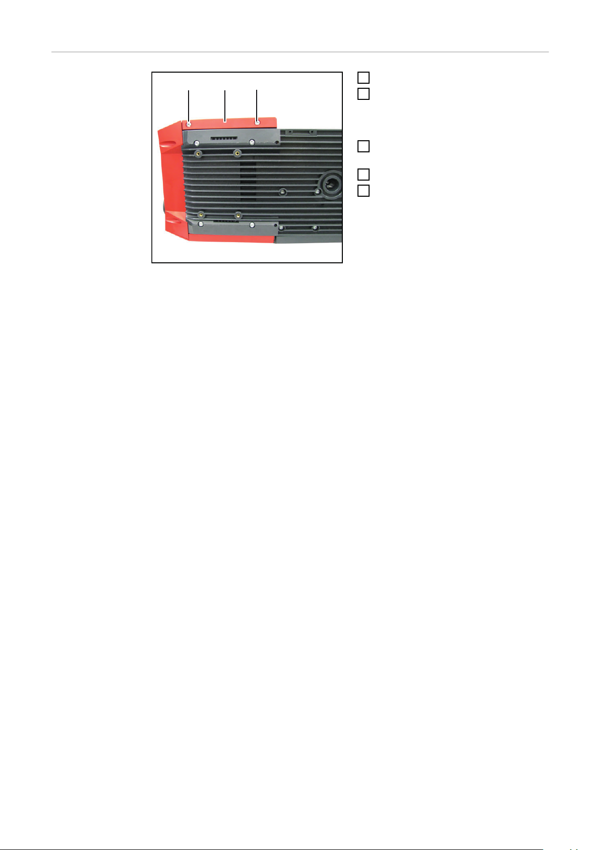
(1) (2)
(1)
Fit the side panel (2)
1
Tighten two 5 x 14 mm screws (1)
2
using TX 25 screwdriver
- Tightening torque = 1.9 Nm
Return wire-feed unit to its original
3
position
Insert wirespool or basket-type spool
4
Restore connections to other system
5
components
24

WF 25i Case (D300): Installing the OPT/i WF ext.
start signal
Safety
WARNING!
Danger due to incorrect operation and incorrectly performed work.
This can result in serious injury and damage to property.
All the work and functions described in this document must only be carried out by
▶
trained and qualified personnel.
Read and understand this document.
▶
Read and understand all the Operating Instructions for the system components,
▶
especially the safety rules.
WARNING!
Electrical current hazard.
This can result in serious injury and damage to property.
Turn the mains switch of the power source to the "O" position and disconnect the
▶
power source from the mains supply.
Secure all the devices and components involved to prevent unintentional restarting.
▶
After opening the device, use a suitable measuring instrument to check that electri-
▶
cally charged components (such as capacitors) have been discharged.
WARNING!
EN
Preparations
Electrical current hazard caused by an inadequate ground conductor connection.
This can result in serious injury and damage to property.
Always use the original housing screws in the original quantity.
▶
CAUTION!
Risk of scalding from hot system components.
This can result in severe scalds.
Before starting work, allow all hot system components to cool down to room tempe-
▶
rature (+25 °C, +77 °F). For example: Coolant, water-cooled system components,
wirefeeder drive motor.
Disconnect all connections on the wire-feed unit from all other system components
1
Take wirespool or basket-type spool off the wire-feed unit
2
Place wire-feed unit on a suitable base
3
25

Installing the
2
1
3
1
2
3
4
1
1
1
2
3
1
OPT/i WF ext.
start signal
1
2
3
5
4
6
26

1
7
1
2
1
X14
1
(1) (2)
1 2 3 4 5 6
12
(3)
(4)
8
EN
9
10
CAUTION!
Danger due to work that has been carried out incorrectly.
This can result in damage to the wire-feed unit through overvoltage.
The robot output for the "OPT/i ext. start signal" option must be a floating output.
▶
Connect the cables (1) and (2) from
11
the socket (3) to the X14 plug (11) as
indicated
- X14:6 'Gun Trigger' signal
- X14:12 'GND' signal
27

X14
1
12
1
2
1
2
3
4
5
1
2
3
(5)(7) (6) (5)
(7)
(8)
13
14
15
Undo the screws (5) of the connecting
16
plug provided and remove the plug
insert (6) from the plug housing
Undo the screw (7) and remove the
17
strain-relief device (8) from the plug
housing
28

7
8
9
5
4
3
2
1
6
(9)
(6)
Guide the cable (9) of the customer-
(8)
(7)
(5)
(6)
(5)
(7)
18
provided controller through the plug
housing
Solder the wires of the cable (9) on pin
19
9 and 5 of the plug insert (6) (see
wire-feed unit circuit diagram)
Insert the plug insert (6) into the plug
20
housing and secure with two screws
(5)
Insert the strain-relief device (8) into
21
the plug housing and secure with a
screw (7)
Connect the connecting plug to the
22
socket (3)
EN
And finally...
Return wire-feed unit to its original position
1
Insert wirespool or basket-type spool
2
Restore connections to other system components
3
NOTE!
If the connecting plug provided is not
connected to the socket (3), insert the
dummy connector (4) into the socket
(3) - otherwise the device will not have
the IP protection.
29

30

Sommaire
Généralités 32
Contenu de la livraison 32
Objectifs pour la sortie du robot 32
WF 15/25/30i: Signal de démarrage ext. OPT/i WF 33
Sécurité 33
Travaux de préparation 34
Installer le signal de démarrage ext. OPT/i WF 34
Étapes finales 38
WF 25i Case (D300): Signal de démarrage ext. OPT/i WF 39
Sécurité 39
Préparations 39
Installer le signal de démarrage ext. OPT/i WF 40
Opérations finales 43
FR
31

Généralités
(2)
(3)
(4)
(5)
(6)
(7)
(1)
Contenu de la livraison
Objectifs pour la
sortie du robot
(1) Connecteur
(2) Connexion avec prise borgne
(3) 2 x écrous M4
(4) 2 x rondelles M4
(5) 2 x rondelles en éventail M4
(6) 2 x vis (2,9 mm x 16 mm)
(7) Faisceau de câbles avec socle
Non représenté :
- le présent document
ATTENTION!
Danger en cas d'erreurs en cours d'opération.
Cela peut entraîner des dommages matériels au niveau du dévidoir en cas de surtension.
La sortie du robot pour l'option « signal de démarrage ext. OPT/i WF » doit être sans
▶
potentiel.
32

WF 15/25/30i: Signal de démarrage ext. OPT/i WF
Sécurité
AVERTISSEMENT!
Risque en cas d'erreur de manipulation et d'erreur en cours d'opération.
Cela peut entraîner des dommages corporels et matériels graves.
Toutes les fonctions et tous les travaux décrits dans le présent document doivent
▶
uniquement être exécutés par du personnel qualifié.
Le présent document doit être lu et compris.
▶
Toutes les instructions de service des composants périphériques, en particulier les
▶
consignes de sécurité, doivent être lues et comprises.
AVERTISSEMENT!
Risque d'électrocution.
Cela peut entraîner la mort ou des blessures graves.
Placer l'interrupteur secteur de la source de courant en position - O - et débrancher
▶
la source de courant du réseau.
S'assurer que tous les appareils et composants concernés ne peuvent pas être
▶
remis en marche.
Après ouverture de l'appareil, s'assurer, à l'aide d'un appareil de mesure approprié,
▶
que les composants à charge électrique (condensateurs, par ex.) sont déchargés.
AVERTISSEMENT!
FR
Risque d'électrocution en cas de connexion de conducteur de terre insuffisante.
Cela peut entraîner des dommages corporels et matériels graves.
Toujours utiliser le nombre initial de vis originales du boîtier.
▶
ATTENTION!
Risque de blessure dû aux composants périphériques chauds.
Cela peut entraîner de graves brûlures.
Avant de débuter les travaux, laisser les composants périphériques refroidir à
▶
température ambiante (+25 °C, +77 °F) notamment : le réfrigérant ; les composants
périphériques refroidis à l'eau ; le moteur entraînant le dévidoir.
33

Travaux de
(1) (2)
(1)
(1)
(2)
préparation
Débrancher toutes les connexions du
1
dévidoir vers les autres composants
périphériques
Retirer la bobine de fil ou la bobine
2
type panier du dévidoir
Placer le dévidoir sur un support
3
adapté
Desserrer les 2 vis TX 25 (1)
4
Retirer la partie latérale droite (2)
5
Installer le signal
de démarrage
ext. OPT/i WF
Retirer la fausse prise (1)
1
Mettre la connexion (2) en place
2
comme indiqué sur l'illustration
34

(7)
(6)
(5)
(7)
(6)
(5)
(3)
(4)
Limer les zones (3) à droite et à gau-
(9)
(9)
(8)
(10)
(11)
3
che du boîtier du dévidoir jusqu'à ce
que les perçages (4) de la connexion
(2) ne soient plus couverts par le
boîtier du dévidoir
Visser la connexion (2) comme
4
indiqué sur l'illustration à l'aide des
rondelles (5), des rondelles en éventail (6) et des écrous (7) fournis
Faire passer le faisceau de câbles du
5
socle (8) par la connexion (2) jusqu'à
l'intérieur de l'appareil
Mettre le socle (8) en place de
6
manière à ce que les deux contacts
(10) se trouvent à gauche - depuis la
vue arrière du dévidoir
Visser le socle (8) à l'aide des vis four-
7
nies 2,9 mm x 16 mm (9)
FR
Débrancher le connecteur X14 (11) du
8
circuit imprimé SR63 dans le dévidoir
35

(11)
(12)(13)
1 2 3 4 5 6
12
Raccorder les câbles (12) et (13) du
(14)
(11)
(16)(18) (17) (16)
(18)
(19)
9
socle (8) conformément à ce qui est
inscrit sur le connecteur X14 (11).
- Signal X14:6 « Gun Trigger »
- Signal X14:12 « GND »
Brancher le connecteur X14 (11) à sa
10
position d'origine sur le circuit imprimé
SR63
Placer le faisceau de câbles (14) du
11
socle (8) comme illustré
Desserrer les vis (16) du connecteur
12
fourni et retirer l'insert de connecteur
(17) du boîtier connecteur
Desserrer la vis (18) et retirer l'anti-
13
traction (19) du boîtier connecteur
36

7
8
9
5
4
3
2
1
6
(20)
(17)
Faire passer le câble (20) de la com-
(16)
(17)
(16)
(18)
(19)
(18)
(8)
(15)
14
mande fournie par le client à travers le
boîtier connecteur
Souder par brasage les fils du câble
15
(20) aux broches 9 et 5 de l'insert de
connecteur (17) (voir également le
schéma de connexions du dévidoir)
Mettre l'insert de connecteur (17) en
16
place dans le boîtier connecteur et le
visser avec deux vis (16)
Mettre l'anti-traction (19) en place
17
dans le boîtier connecteur et le visser
à l'aide d'une vis (18)
Raccorder le connecteur au socle (8)
18
FR
ATTENTION!
Danger en cas d'erreurs en cours
d'opération.
Cela peut entraîner des dommages
matériels au niveau du dévidoir en cas de
surtension.
La sortie du robot pour
▶
l'option « Signal de démarrage ext.
OPT/i WF » doit être sans potentiel.
REMARQUE!
Si le connecteur fourni n'est pas raccordé au socle (8), brancher la prise
borgne (15) sur le socle (8).
C'est la seule manière de garantir que
l'indice de protection IP de l'appareil soit
atteint.
37

Étapes finales
(1) (2)
(1)
Mettre en place la partie latérale (2)
1
Visser les 2 vis 5 x 14 mm (1) à l'aide
2
du tournevis TX 25
- Couple de serrage = 1,9 Nm
Replacer le dévidoir dans sa position
3
initiale
Mettre en place la bobine de fil ou la
4
bobine type panier
Rétablir la connexion avec les autres
5
composants périphériques
38

WF 25i Case (D300): Signal de démarrage ext. OPT/i
WF
Sécurité
AVERTISSEMENT!
Risque en cas d'erreur de manipulation et d'erreur en cours d'opération.
Cela peut entraîner des dommages corporels et matériels graves.
Toutes les fonctions et tous les travaux décrits dans le présent document doivent
▶
uniquement être exécutés par du personnel qualifié.
Le présent document doit être lu et compris.
▶
Toutes les instructions de service des composants périphériques, en particulier les
▶
consignes de sécurité, doivent être lues et comprises.
AVERTISSEMENT!
Risque d'électrocution.
Cela peut entraîner la mort ou des blessures graves.
Placer l'interrupteur secteur de la source de courant en position - O - et débrancher
▶
la source de courant du réseau.
S'assurer que tous les appareils et composants concernés ne peuvent pas être
▶
remis en marche.
Après ouverture de l'appareil, s'assurer, à l'aide d'un appareil de mesure approprié,
▶
que les composants à charge électrique (condensateurs, par ex.) sont déchargés.
AVERTISSEMENT!
FR
Préparations
Risque d'électrocution en cas de connexion de conducteur de terre insuffisante.
Cela peut entraîner des dommages corporels et matériels graves.
Toujours utiliser le nombre initial de vis originales du boîtier.
▶
ATTENTION!
Risque de blessure dû aux composants périphériques chauds.
Cela peut entraîner de graves brûlures.
Avant de débuter les travaux, laisser les composants périphériques refroidir à
▶
température ambiante (+25 °C, +77 °F) notamment : le réfrigérant ; les composants
périphériques refroidis à l'eau ; le moteur entraînant le dévidoir.
Débrancher toutes les connexions du dévidoir vers les autres composants du
1
système
Retirer la bobine de fil ou la bobine type panier du dévidoir
2
Placer le dévidoir sur un support adapté
3
39

Installer le signal
2
1
3
1
2
3
4
1
1
1
2
3
1
de démarrage
ext. OPT/i WF
1
2
3
5
4
6
40

1
7
1
2
1
X14
1
(1) (2)
1 2 3 4 5 6
12
(3)
(4)
8
FR
9
10
ATTENTION!
Danger en cas d'erreurs en cours d'opération.
Cela peut entraîner des dommages matériels au niveau du dévidoir en cas de surtension.
La sortie du robot pour l'option « Signal de démarrage ext. OPT/i WF » doit être
▶
sans potentiel.
Raccorder les câbles (1) et (2) du
11
socle (3) conformément à ce qui est
inscrit sur le connecteur X14 (11)
- Signal X14:6 « Gun Trigger »
- Signal X14:12 « GND »
41

X14
1
12
1
2
1
2
3
4
5
1
2
3
(5)(7) (6) (5)
(7)
(8)
13
14
15
Desserrer les vis (5) du connecteur
16
fourni et retirer l'insert de connecteur
(6) du boîtier connecteur
Desserrer la vis (7) et retirer l'anti-trac-
17
tion (8) du boîtier connecteur
42

7
8
9
5
4
3
2
1
6
(9)
(6)
Faire passer le câble (9) de la com-
(8)
(7)
(5)
(6)
(5)
(7)
18
mande fournie par le client à travers le
boîtier connecteur
Souder par brasage les fils du câble
19
(9) aux broches 9 et 5 de l'insert de
connecteur (6) (voir également le
schéma de connexions du dévidoir)
Mettre l'insert de connecteur (6) en
20
place dans le boîtier connecteur et le
visser avec deux vis (5)
Mettre l'anti-traction (8) en place dans
21
le boîtier connecteur et le visser à
l'aide d'une vis (7)
Raccorder le connecteur au socle (3)
22
FR
Opérations finales
REMARQUE!
Si le connecteur fourni n'est pas raccordé au socle (3), brancher la prise
borgne (4) sur le socle (3).
C'est la seule manière de garantir que
l'indice de protection IP de l'appareil soit
atteint.
Replacer le dévidoir dans sa position initiale.
1
Mettre en place la bobine de fil ou la bobine type panier du dévidoir.
2
Rétablir la connexion avec les autres composants périphériques.
3
43

FRONIUS INTERNATIONAL GMBH
Froniusstraße 1
A-4643 Pettenbach
AUSTRIA
contact@fronius.com
www.fronius.com
Under www.fronius.com/contact you will find the addresses
of all Fronius Sales & Service Partners and locations
 Loading...