


/ Perfect Charging / Perfect Welding / Solar Energy
OPT/i WF Ausblasen extern
OPT/i WF external gas purging
Installationsanleitung
DEEN-US
Systemerweiterung
Installation Instructions
System extension
42,0410,2387 001-23102017

2

Inhaltsverzeichnis
Allgemeines ............................................................................................................................................... 5
Allgemeines .......................................................................................................................................... 5
Voraussetzung...................................................................................................................................... 5
Lieferumfang......................................................................................................................................... 5
Erforderliche Werkzeuge ...................................................................................................................... 5
OPT/i WF Ausblasen extern einbauen....................................................................................................... 6
Sicherheit.............................................................................................................................................. 6
Vorbereitung ......................................................................................................................................... 6
OPT/i WF Ausblasen extern einbauen.................................................................................................. 7
Abschließende Tätigkeiten.................................................................................................................... 9
DE
3

4

Allgemeines
Allgemeines Die Option kann in die Drahtvorschübe WF 15i / 25i / 30i R und R PAP eingebaut werden,
sofern die Drahtvorschübe mit einem der folgenden Schweißbrenner-Anschlüsse ausgestattet sind:
- Euro
- Fronius F++
- Tewco
Voraussetzung Die Option OPT/i WF Ausblasen extern funktioniert nur in Verbindung mit
- der OPT/i WF Brenner Steuerung
+
- einer Ausblas-Option
(OPT/i WF Ausblasen 7 bar oder OPT/i WF Ausblasen 16 bar)
DE
Lieferumfang
Erforderliche
Werkzeuge
ohne Abbildung:
- diese Installationsanleitung
- Torx-Schraubendreher TX 20
- Gabelschlüssel SW 15 mm
- Seitenschneider
- Hammer
- Schlitz-Schraubendreher
- Messer
- Feile
5

OPT/i WF Ausblasen extern einbauen
Sicherheit
WARNUNG! Fehlbedienung und fehlerhaft durchgeführte Arbeiten können
schwerwiegende Personen- und Sachschäden verursachen.
Alle in diesem Dokument beschriebenen Arbeiten und Funktionen dürfen nur von
geschultem Fachpersonal ausgeführt werden, wenn folgende Dokumente vollständig gelesen und verstanden wurden:
- dieses Dokument
- sämtliche Bedienungsanleitungen der Systemkomponenten, insbesondere
Sicherheitsvorschriften
WARNUNG! Ein elektrischer Schlag kann tödlich sein. Vor Beginn der Arbeiten:
- Netzschalter der Stromquelle in Stellung - O - schalten
- Stromquelle vom Netz trennen
- sicherstellen, dass die Stromquelle bis zum Abschluss aller Arbeiten vom
Netz getrennt bleibt
Nach dem Öffnen des Gerätes mit Hilfe eines geeigneten Messgerätes sicherstellen, dass elektrisch geladene Bauteile (z.B. Kondensatoren) entladen sind.
VORSICHT! Verletzungsgefahr durch heiße Systemkomponenten. Vor Beginn
der Arbeiten alle heißen Systemkomponenten auf Zimmertemperatur (+25 °C,
+77 °F) abkühlen lassen, beispielsweise:
- Kühlmittel
- wassergekühlte Systemkomponenten
- Antriebsmotor des Drahtvorschubes
Vorbereitung
Sämtliche Verbindungen des Gerätes von allen anderen Systemkomponenten tren-
1
nen
Gerät auf einer geeigneten Unterlage ablegen
2
4 Schrauben TX 20 (1) lösen
3
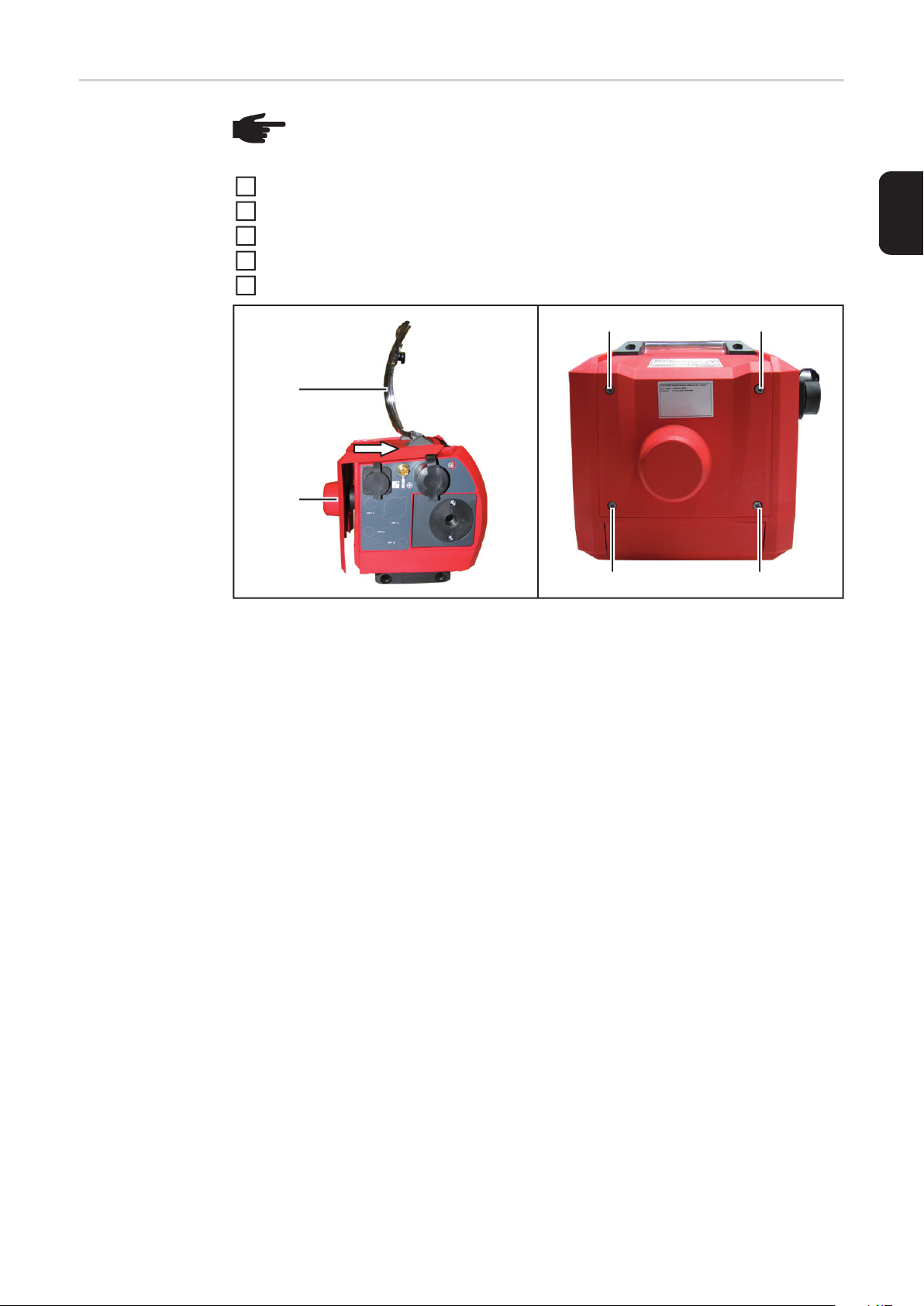
Abdeckung (2) öffnen
4
Gehäuseabdeckung (3) wie abgebildet vom Gerät abziehen
5
(1)
(1) (1)
(1)
(2)
(3)
6

OPT/i WF Ausblasen extern einbauen
Die Folie über der Markierung
1
OPT 4
DE
mit einem Messer gemäß Abbildung
ausschneiden und entfernen
(1)
VORSICHT! Gefahr von Verletzungen durch herumfliegende
2
Kunststoff-Teile. Beim Herausbrechen des Kunststoff-Platzhalters
(1) eine Schutzbrille tragen und sicherstellen, dass sich keine weiteren Personen im Arbeitsbereich
befinden.
Den Kunststoff-Platzhalter (1) mittels
2
Hammer und Schlitz-Schraubendreher
ausbrechen
Überstehende Ausbruchkanten mit ei-
3
ner Feile entfernen
Kunststoffmutter (3) vom Anschluss
4
Ausblasen extern (2) abschrauben
5
Anschluss Ausblasen extern (2) von in-
5
nen nach außen in die Öffnung einsetzen
Anschluss Ausblasen extern (2) mittels
6
Kunststoffmutter (3) fixieren
SW 15 mm
(2)
(5)
(4)
(3)
Der gelbe Schlauch (4) ist im Lieferumfang
der Ausblas-Option enthalten.
Gelben Schlauch (4) am Anschluss
8
7
7
Ausblasen extern anstecken
Sechskantmutter (5) festziehen
8
SW 13 mm
7

(4) 15-20 mm
10
Gelben Schlauch (4) gemäß Abbildung
9
ablängen
Gelben Schlauch (4) am Ausblasen-
10
Ventil (6) anstecken
(4) (6)
8

Abschließende
Tätigkeiten
HINWEIS! Beim Montieren der Gehäuseabdeckung sicherstellen, dass Kabel
und Schläuche nicht geknickt, eingeklemmt, abgescheuert oder auf andere Weise beschädigt werden.
Gehäuseabdeckung (3) wie abgebildet bis auf Anschlag auf das Gerät aufschieben
1
4 Schrauben TX 20 (1) festschrauben
2
Abdeckung (2) schließen
3
Gerät in seine Ausgangsposition bringen
4
Verbindungen mit anderen Systemkomponenten herstellen
5
DE
(2)
(3)
(1)
(1) (1)
(1)
9

10

Contents
General ...................................................................................................................................................... 13
General ................................................................................................................................................. 13
Requirements........................................................................................................................................ 13
Scope of supply .................................................................................................................................... 13
Tools required....................................................................................................................................... 13
Install OPT/i WF external gas purging ....................................................................................................... 14
Safety.................................................................................................................................................... 14
Preparation ........................................................................................................................................... 14
Install OPT/i WF external gas purging .................................................................................................. 15
Final tasks............................................................................................................................................. 17
EN-US
11

12

General
General The option can be installed in the wirefeeder WF 15i / 25i / 30i R and R PAP if the wire-
feeders are equipped with one of the following welding torch connectors:
- Euro
- Fronius F++
- Tewco
Requirements The OPT/i WF external gas purging option is only available in conjunction with
- the OPT/i WF torch control socket
+
- a gas purging option
(OPT/i WF gas purging 7 bar or OPT/i WF gas purging 16 bar)
EN-US
Scope of supply
Tools required - Torx screwdriver TX 20
- Size 15 mm wrench
- Diagonal cutting pliers
- Hammer
- Slotted screwdriver
- Knife
- File
not shown:
- this set of Installation Instructions
13

Install OPT/i WF external gas purging
Safety
WARNING! Incorrect operation and faulty work can cause serious personal injury
and material damage.
All work and functions described in this document must be performed only by
trained specialist personnel who have read and understood the following documents in full:
- this document
- all OIs for system components, especially the safety rules
WARNING! An electric shock can be fatal. Before beginning work:
- Switch the power source to - O -
- Disconnect the power source from the grid
- Ensure that the power source remains disconnected from the grid until all
work is complete
After opening the device, use a suitable measuring tool to ensure that electrically
charged components (e.g. capacitors) are discharged.
CAUTION! Risk of injury from hot system components. Before starting work, allow all hot system components to cool to room temperature (+25 °C, +77 °F), for
example:
- Coolant
- Water-cooled system components
- Wirefeeder drive motor
Preparation
Disconnect the device from all other system components
1
Place the device on a temporary backing
2
Remove 4 TX 20 screws (1)
3
Open the wirefeeder cover (2)
4
Remove the wirefeeder housing cover (3) from the unit as shown
5
(1)
(1) (1)
(1)
(2)
(3)
14

Install OPT/i WF
external gas
purging
Cut and remove the film above the
1
OPT 4
mark with a knife as shown
(1)
2
CAUTION! DANGER! Injuries can
be caused by flying debris from
plastic parts. Wear protective goggles when breaking the plastic
EN-US
spacer (1) and make sure there
are no other persons in the working area.
Break the plastic spacer (1) with a
2
hammer and a slotted screwdriver
Remove any breakout edges with a file
3
Unscrew the plastic nut (3) from the ex-
4
ternal gas purging connection(2)
5
Insert the external gas purging connec-
5
tion (2) from the inside to the outside
into the opening
Fix the connection for external gas pur-
6
ging (2) with a plastic nut (3)
SW 15 mm
(2)
(3)
(5)
(4)
The yellow hose (4) is included in the scope
of delivery of the gas purging option.
Connect the yellow hose (4) to the
8
7
7
connection for external gas purging
Tighten the hexagon nut (5)
8
SW 13 mm
15

(4) 15-20 mm
10
Trim the yellow hose (4) as shown
9
Connect the yellow hose (4) to the gas
10
purging valve (6)
(4) (6)
16
Final tasks
NOTE! When installing the wirefeeder housing cover, make sure that the cables
and hoses are not kinked, pinched, abraded or otherwise damaged.
Push the wirefeeder housing cover (3) onto the device as far as it will go
1
Tighten 4 TX 20 screws (1)
2
Close the wirefeeder cover (2)
3
Move the device to its home position
4
Connect to other system components
5
EN-US
(2)
(3)
(1)
(1) (1)
(1)
17

18

EN-US
19

FRONIUS INTERNATIONAL GMBH
Froniusplatz 1, A-4600 Wels, Austria
Tel: +43 (0)7242 241-0, Fax: +43 (0)7242 241-3940
E-Mail: sales@fronius.com
www.fronius.com
www.fronius.com/addresses
Under http://www.fronius.com/addresses you will find all addresses
of our Sales & service partners and Locations
 Loading...