


Installation
Instructions
OPT/i WF Ausblasen 16 bar
OPT/i WF 16 bar gas purging
Installationsanleitung
DE
Installation instructions
EN
42,0410,1972 006-11102022


Inhaltsverzeichnis
Allgemeines 4
Sicherheit 4
Allgemeines 4
Lieferumfang 5
Erforderliche Werkzeuge 5
Vorgaben für die Druckluft-Versorgung 5
OPT/i WF Ausblasen 16 bar einbauen 6
Vorbereitung 6
OPT/i WF Ausblasen 16 bar einbauen 6
Abschließende Tätigkeiten 9
DE
3

Allgemeines
Sicherheit
WARNUNG!
Gefahr durch Fehlbedienung und fehlerhaft durchgeführte Arbeiten.
Schwerwiegende Personen- und Sachschäden können die Folge sein.
Alle in diesem Dokument beschriebenen Arbeiten und Funktionen dürfen
▶
nur von geschultem Fachpersonal ausgeführt werden.
Dieses Dokument lesen und verstehen.
▶
Sämtliche Bedienungsanleitungen der Systemkomponenten, insbesondere
▶
Sicherheitsvorschriften lesen und verstehen.
WARNUNG!
Gefahr durch elektrischen Strom.
Schwerwiegende Personen- und Sachschäden können die Folge sein.
Alle beteiligten Geräte und Komponenten ausschalten und von Stromnetz
▶
trennen.
Alle beteiligten Geräte und Komponenten gegen Wiedereinschalten sichern.
▶
Nach dem Öffnen des Gerätes mit Hilfe eines geeigneten Messgerätes si-
▶
cherstellen, dass elektrisch geladene Bauteile (beispielsweise Kondensatoren) entladen sind.
WARNUNG!
Gefahr durch elektrischen Strom wegen unzureichender Schutzleiter-Verbindung.
Schwerwiegende Personen- und Sachschäden können die Folge sein.
Immer die originalen Gehäuse-Schrauben in der ursprünglichen Anzahl ver-
▶
wenden.
VORSICHT!
Gefahr durch heiße Schweißbrenner-Komponenten und heißes Kühlmittel.
Schwere Verbrühungen können die Folge sein.
Vor Beginn aller in diesem Dokument beschriebenen Arbeiten, sämtliche
▶
Schweißbrenner-Komponenten und das Kühlmittel auf Zimmertemperatur
(+25 °C / +77 °F) abkühlen lassen.
Allgemeines Die Option kann bei folgenden Geräten eingebaut werden
alle Varianten der Geräte WF 15i/25i/30i R und R PAP
-
alle Varianten der Geräte SB 500i R und R PAP
-
Der Einbau der Option wird anhand des Roboter-Drahtvorschubes WF 15i R dargestellt. Bei den anderen Geräten erfolgt der Einbau auf die gleiche Weise.
4

Lieferumfang
(1)
(2) (3) (4) (5) (7) (8)
(6)
(1) Schlauch PA 100 mm
(2) 2 Wege Magnetventil
(3) Kupplung Druckluft Teil 1
(4) Kupplung Druckluft Teil 2
(5) Druckluft-Anschluss
(6)
Pass-Scheibe Æ
13 x 0,3 mm
(7) Winkel-Steckanschluss
(8) Einsatz 16 bar
(9) Kabelbaum Option Ausblasen
16 bar (nicht abgebildet)
(10) Diese Einbauanleitung (nicht
abgebildet)
DE
Erforderliche
Werkzeuge
Vorgaben für die
Druckluft-Versorgung
Torx-Schraubendreher TX 20
-
Torx-Schraubendreher TX 25
-
Gabelschlüssel SW 17 mm
-
Messer
-
Gewindedichtung (z.B. Teflonband, Loctite, etc.)
-
Um die ordnungsgemäße Funktion sicherzustellen, folgende Vorgaben für die
Druckluft-Versorgung erfüllen:
Druckluft-Versorgung mit mindestens 5 bar konstant
-
Druckluft frei von Öl
-
Druckluft frei von Wasser
-
Druckluft frei von Staub - keine Verunreinigungen größer als 5 µm
-
5
OPT/i WF Ausblasen 16 bar einbauen
(1)
(1) (1)
(1)
(3)
(2)
2
1
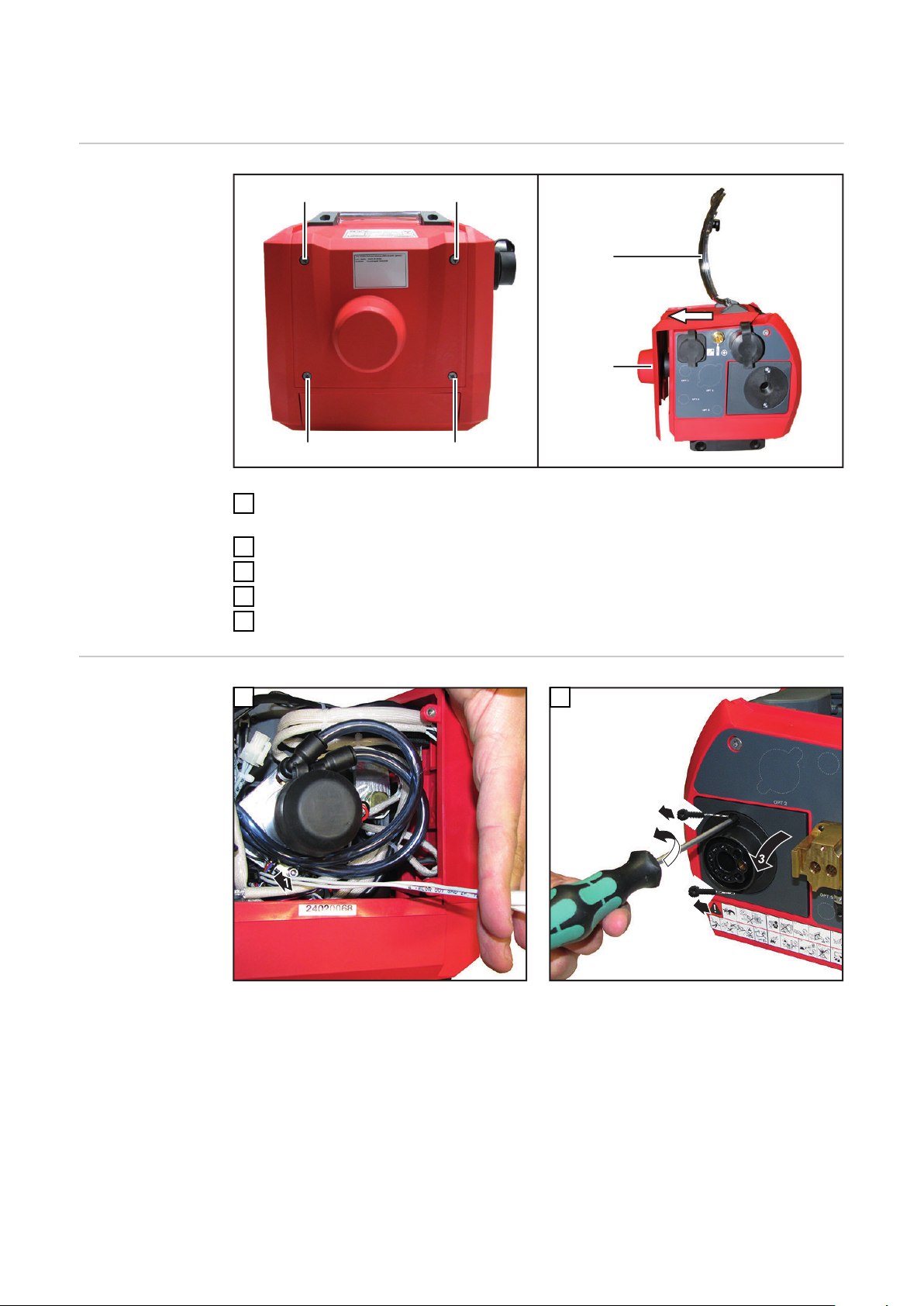
Vorbereitung
Sämtliche Verbindungen des Gerätes von allen anderen Systemkomponenten
1
trennen
Gerät auf einer geeigneten Unterlage ablegen
2
4 Schrauben TX 20 (1) lösen
3
Abdeckung (2) öffnen
4
Gehäuseabdeckung (3) wie abgebildet vom Gerät abziehen
5
OPT/i WF Ausblasen 16 bar
einbauen
1
Kabelbaum Option Ausblasen 16 bar am Kabelbaum Magnetventil anstecken
2
6

3 4
1
3
2 x 3 Nm
(1)
DE
5
Achtung - keine Kabel einklemmen!
6
Durchführung bei OPT 4 (1) aus-
7
brechen oder mit Messer entfernen
Überstehenden Grat mit Messer
8
wegschneiden
7

9
SW 17 mm
10
Kabelbaum Option Ausblasen 16 bar am Magnetventil anstecken
11
Zum Einbau der Option müssen die Kabel und
Leitungen im Gerät beiseite geschoben werden
WICHTIG! Vor dem Einsetzen des Druckluft-Anschlusses das Gewinde eindichten (z.B. mittels
Teflonband oder Loctite)
12
WF 15i mit eingebauter Option Ausblasen 16
bar
8

Abschließende
(3)
(2)
(1)
(1) (1)
(1)
Tätigkeiten
HINWEIS!
Beim Montieren der Gehäuseabdeckung sicherstellen, dass Kabel und
Schläuche nicht geknickt, eingeklemmt, abgescheuert oder auf andere Weise
beschädigt werden.
Gehäuseabdeckung (3) wie abgebildet bis auf Anschlag auf das Gerät auf-
1
schieben
4 Schrauben TX 20 (1) festschrauben
2
Abdeckung (2) schließen
3
Gerät in seine Ausgangsposition bringen
4
Verbindungen mit anderen Systemkomponenten herstellen
5
DE
9

10

Contents
General 12
Safety 12
General 12
Scope of supply 13
Tools required 13
Compressed air supply specifications 13
Installing the OPT/i WF 16 bar gas purging 14
Preparations 14
Installing OPT/i WF 16 bar gas purging 14
And finally... 17
EN
11

General
Safety
WARNING!
Danger due to incorrect operation and incorrectly performed work.
This can result in serious injury and damage to property.
All the work and functions described in this document must only be carried
▶
out by trained and qualified personnel.
Read and understand this document.
▶
Read and understand all the Operating Instructions for the system compon-
▶
ents, especially the safety rules.
WARNING!
Danger from electric current.
This can result in serious injury and damage to property.
Switch off all the devices and components involved and disconnect them
▶
from the grid.
Secure all the devices and components involved to prevent unintentional re-
▶
starting.
After opening the device, use a suitable measuring instrument to check that
▶
electrically charged components (such as capacitors) have been discharged.
WARNING!
Danger from electrical current due to inadequate ground conductor connection.
This can result in serious injury and damage to property.
Always use the original housing screws in the original quantity.
▶
CAUTION!
Danger of burns from hot welding torch components and hot coolant.
This can result in severe scalds.
Before commencing any of the work described in this document, allow all
▶
welding torch components and the coolant to cool to room temperature
(+25°C, +77°F).
General The option can be installed in the following devices:
all variants of the WF 15i/25i/30i R and R PAP
-
all variants of the SB 500i R and R PAP
-
The installation of this option is illustrated using the WF 15i R robot wire-feed
unit as an example. Installation on other devices is carried out in the same way.
12

Scope of supply
(1)
(2) (3) (4) (5) (7) (8)
(6)
(1) PA 100 mm hose
(2) 2-way solenoid valve
(3) Compressed air coupling, part 1
(4) Compressed air coupling, part 2
(5) Compressed air connection
(6)
Shim ring Æ
13 x 0.3 mm
(7) Elbow connector
(8) 16 bar insert
(9) 16 bar cable harness, gas pur-
ging option (not shown)
(10) These Installation Instructions
(not shown)
EN
Tools required
Compressed air
supply specifications
TX 20 TORX® screwdriver
-
TX 25 TORX® screwdriver
-
17 mm flat spanner
-
Knife
-
Thread sealant (e.g. Teflon tape, Loctite, etc.)
-
To ensure that it functions correctly, the following compressed air supply specifications must be met:
Constant compressed air supply of at least 5 bar
-
Compressed air is free of oil
-
Compressed air is free of water
-
Compressed air is free of dust – no dirt particles larger than 5 µm
-
13

Installing the OPT/i WF 16 bar gas purging
(1)
(1) (1)
(1)
(3)
(2)
2
1
Preparations
Disconnect all connections on the device from all other system components
1
Place the device on a suitable base
2
Undo four TX 20 screws (1)
3
Open cover (2)
4
Pull the housing cover (3) off the device as shown
5
Installing OPT/i
WF 16 bar gas
purging
1
Connecting the 16 bar gas purging option cable
harness to the solenoid valve cable harness
2
14

3 4
1
3
2 x 3 Nm
(1)
EN
5
Caution – be careful not to trap any cables.
6
Break off the OPT 4 bushing (1) or
7
remove it using the knife
Cut away any protruding flash with
8
the knife
15

9
SW 17 mm
10
Connecting the 16 bar gas purging option cable
harness to the solenoid valve
11
The cables and lines inside the device must be
moved aside in order to install this option
IMPORTANT! Before inserting the compressed
air connection, seal the thread (e.g. by means of
Teflon tape or Loctite)
12
WF 15i with 16 bar gas purging option installed
16

And finally...
(3)
(2)
(1)
(1) (1)
(1)
NOTE!
When fitting the housing cover, ensure that the cables and hoses are not kinked,
trapped, sheared or damaged in any way.
Push housing cover (3) as far as it will go onto the device as shown
1
Tighten the four TX 20 screws (1)
2
Close the cover (2)
3
Return the device to its original position
4
Establish connections to other system components
5
EN
17

18

EN
19

 Loading...