


/ Perfect Charging / Perfect Welding / Solar Energy
OPT/i TXi i/O
Installationsanleitung
DEEN-US
Systemerweiterung
Installation Instructions
System extension
42,0410,0964 001-17052018

2
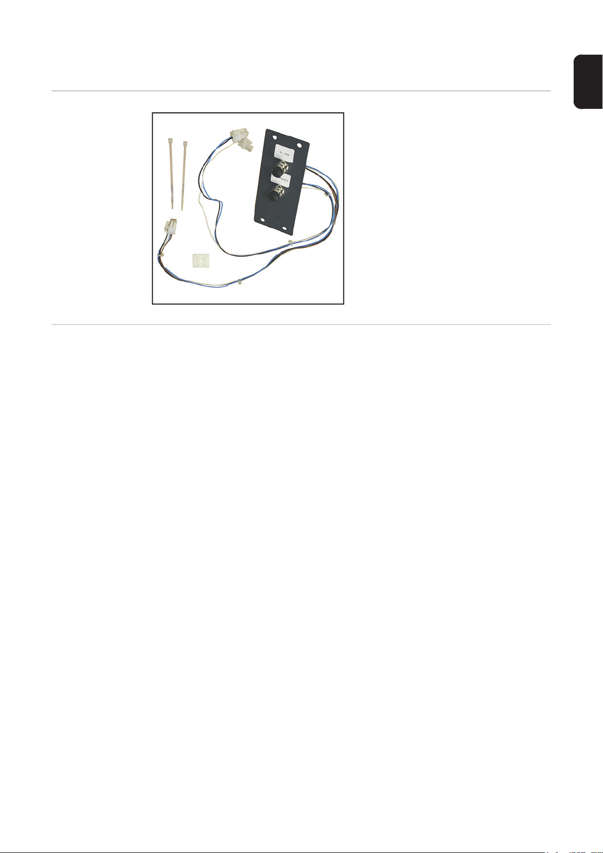
Lieferumfang und erforderliches Werkzeug
DE
Lieferumfang
Erforderliches
Werkzeug
ohne Abbildung:
- diese Anleitung
- Innensechskant-Schlüssel SW 5 mm
- Innensechskant-Schlüssel SW 4 mm
- Sechskant-Schlüssel SW 8 mm
- Seitenschneider
3
OPT/i TX/i I/O einbauen
Sicherheit
WARNUNG! Fehlbedienung und fehlerhaft durchgeführte Arbeiten können
schwerwiegende Personen- und Sachschäden verursachen.
Alle in diesem Dokument beschriebenen Arbeiten und Funktionen dürfen nur von
geschultem Fachpersonal ausgeführt werden, wenn folgende Dokumente vollständig gelesen und verstanden wurden:
- dieses Dokument
- sämtliche Bedienungsanleitungen der Systemkomponenten, insbesondere
Sicherheitsvorschriften
WARNUNG! Ein elektrischer Schlag kann tödlich sein. Vor Beginn der Arbeiten
alle beteiligten Geräte und Komponenten
- ausschalten
- vom Stromnetz trennen
- gegen Wiedereinschalten sichern.
Nach dem Öffnen des Gerätes mit Hilfe eines geeigneten Messgerätes sicherstellen, dass elektrisch geladene Bauteile (z.B. Kondensatoren) entladen sind.
WARNUNG! Unzureichende Schutzleiter-Verbindung kann schwerwiegende
Personen- und Sachschäden verursachen. Die Gehäuse-Schrauben stellen eine
geeignete Schutzleiter-Verbindung für die Erdung des Gehäuses dar und dürfen
keinesfalls durch andere Schrauben ohne zuverlässige Schutzleiter-Verbindung
ersetzt werden.
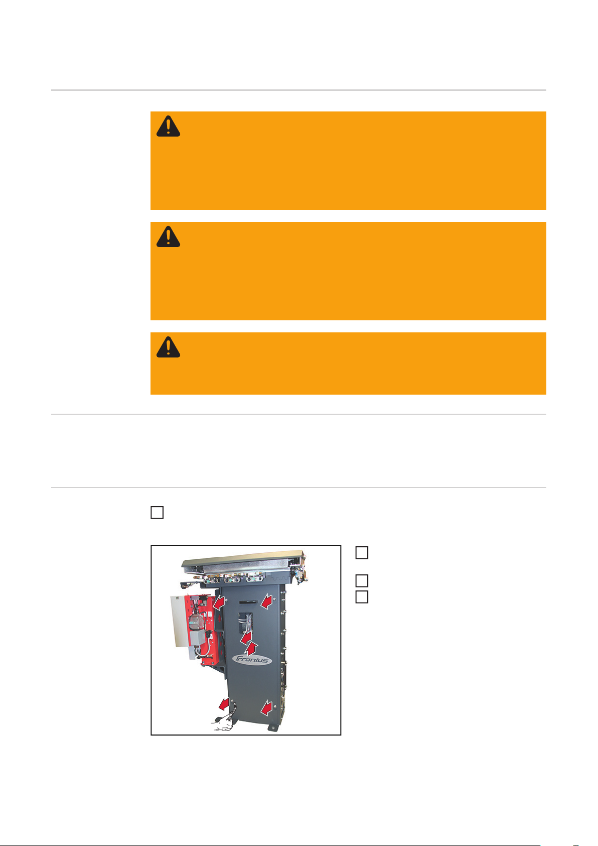
Allgemeines Der Einbau der Option OPT/i TXi I/O wird an einer Geräteausführung mit Feldbus-Anbin-
dung beschrieben.
Der Einbau in eine Geräteausführung mit Standard I/O Anbindung erfolgt analog dazu.
Vorbereitung Sämtliche Verbindungen der Brennerkörper-Wechselstation zu den anderen System-
1
komponenten und zur Roboter-Steuerung trennen
4 Innensechskant-Schrauben SW 5
2
mm lösen
Seitenteil anheben und ...
3
... entnehmen
2
2
2
4
3
2
4
4

4 Innensechskant-Schrauben SW 4
*
5
mm an der Vorderseite entfernen
DE
*
5
5
an der Innenseite mit Gabelschlüssel
SW 8 mm gegenhalten
Die 4 Innensechskant-Schrauben SW
6
4 mm und die dazugehörenden Sechskant-Muttern werden noch für weitere
Montageschritte benötigt.
Abdeckung entfernen
5
5
6
OPT/i TXi I/O einbauen
*
Anschlussplatte von innen nach außen
1
gemäß Abbildung in die Öffnung einsetzen
2
2
Anschlussplatte mit 4 Innensechskant-
2
Schrauben SW 4 mm und 4 Sechskant-Muttern SW 8 mm * montieren
1
2
2
4-poliges Kabel
3
(schwarz / blau / weiß / braun)
von der Anschlussplatte am Verteiler-
3
Print auf X28 anstecken
3
3
3
5

2-poliges Kabel
4
5
5
4
(schwarz / blau)
von der Anschlussplatte am VerteilerPrint auf X18 anstecken
Anschluss-Übersicht:
X1 X2 X3 X4 X5 X6 X7
X23
X22X21
4
Bei Geräteausführung mit Feldbus-Anbindung das 1-polige weiße Kabel hinter den vorhandenen Kabeln des
4
Feldbusses verlegen.
1-poliges Kabel
5
(weiß)
4
von der Anschlussplatte am VerteilerPrint auf X23 anstecken
4
X10X8
X9
X20X19X18X17X16X15X14X13X12X11
X26X25X24
4
X27 X28 X29
5
1p
white
3
2p
black
blue
Klebesockel anbringen
6
Kabel mittels Kabelbinder am Klebeso-
7
4p
black
blue
white
brown
ckel fixieren
Kabelbinder ablängen
8
7
6
Abschließende
Tätigkeiten
6
Seitenteil einsetzen und mit 4 Innensechskant-Schrauben SW 5 mm fixieren
1
Sämtliche Verbindungen der Brennerkörper-Wechselstation zu den anderen System-
2
komponenten und zur Roboter-Steuerung wieder herstellen

Scope of Supply and Tools Required
Scope of Supply
Required Tools - 5 mm Allen key
- 4 mm Allen key
- 8 mm Allen key
- Diagonal cutting pliers
Not shown:
- These instructions
EN-US
7

Installing OPT/i TXi I/O
Safety
WARNING! Incorrect operation and incorrectly performed work can cause seri-
ous injury and damage to property.
All tasks and functions described in this document must only be carried out by
trained specialist personnel once they have read and understood the following
documents in full:
- this document
- all Operating Instructions for system components, especially the safety rules.
WARNING! An electric shock can be fatal. Before beginning the work, all devices
and components must be:
- switched off
- disconnected from the grid
- prevented from being switched back on.
After opening the device, use a suitable measuring tool to ensure that electrically
charged components (e.g. capacitors) are discharged.
WARNING! An inadequate grounding conductor connection can cause serious
injuries to persons and damage to (or loss of) property. The housing screws provide a suitable grounding conductor connection for the housing ground and
should not be replaced under any circumstances by other screws that do not provide a proper grounding conductor connection.
General The installation of the option OPT/i TXi I/O is described using a version of the appliance
with fieldbus connection.
Installation in a version of the appliance with standard I/O connection is performed in the
same way.
Preparation Disconnect all connections between the torch body change station and the other sys-
1
tem components and the robot controls
Loosen four 5 mm Allen screws
2
Lift the side panel and ...
3
... remove it
4
2
2
2
4
3
2
8

Remove four 4 mm Allen screws on
*
5
the front
*
5
5
press against the inside with 8 mm
wrench
Installing OPT/i
TXi I/O
The four 4 mm Allen screws and the
6
hexagon nuts that go with them are still
EN-US
required for further installation steps.
Remove cover
6
5
5
*
Insert connection plate into the
1
opening from inside out as shown
Mount connection plate using four
2
2
2
4 mm Allen screws and four 8 mm hexagon nuts *
1
2
2
Connect the 4-pin cable
3
(black/blue/white/brown)
from the connection plate on the distri-
3
3
3
3
bution panel PC board to X28
9

Connect the 2-pin cable
4
5
5
4
(black/blue)
from the connection plate on the distribution panel PC board to X18
Connection overview:
X1 X2 X3 X4 X5 X6 X7
X23
X22X21
4
For the version of the appliance with
fieldbus connection, lay the 1-pin white
cable behind the existing fieldbus cab-
4
les.
Connect the 1-pin cable
5
(white)
4
from the connection plate on the distribution panel PC board to X23
4
X10X8
X9
X20X19X18X17X16X15X14X13X12X11
X26X25X24
4
X27 X28 X29
5
1p
white
3
2p
black
blue
Attach adhesive base
6
Fix the cable to the adhesive base
7
4p
black
blue
white
brown
using a cable tie
Trim cable tie
8
7
6
Final Tasks Insert the side panel and fix it with four 5 mm Allen screws
1
Restore all connections between the torch body change station and the other system
2
components and the robot controls
10

EN-US
11

FRONIUS INTERNATIONAL GMBH
Froniusplatz 1, A-4600 Wels, Austria
Tel: +43 (0)7242 241-0, Fax: +43 (0)7242 241-3940
E-Mail: sales@fronius.com
www.fronius.com
www.fronius.com/addresses
Under http://www.fronius.com/addresses you will find all addresses
of our Sales & service partners and Locations
 Loading...