


Fronius prints on elemental chlorine free paper (ECF) sourced from certified sustainable forests (FSC).
/ Perfect Charging / Perfect Welding / Solar Energy
OPT/i TPS Sense Lead
OPT/i WF Sense Lead
Installationsanleitung
DE
Installation instructions
EN-US
42,0410,2660 002-10032022


Inhaltsverzeichnis
Vorbereitende Informationen 5
Sicherheit und Lieferumfang 7
Sicherheit 7
Lieferumfang OPT/i TPS Sense Lead (für Stromquellen) 8
Lieferumfang OPT/i WF Sense Lead (für Drahtvorschübe und Splitboxen) 8
Lieferumfang OPT/i TPS Conversion Sense Lead (für Stromquellen) 8
Stromquelle, Drahtvorschub, SB 500i nach 01.01.2022 produziert 11
OPT/i TPS Sense Lead in Stromquelle einbauen 13
OPT/i TPS Sense Lead einbauen 13
OPT/i WF Sense Lead in Drahtvorschub / SB 500i einbauen 20
OPT/i WF Sense Lead einbauen 20
Stromquelle, Drahtvorschub, SB 500i vor 01.01.2022 produziert 25
OPT/i TPS Sense Lead in Stromquelle einbauen 27
OPT/i TPS Sense Lead einbauen 27
OPT/i WF Sense Lead in Drahtvorschub / SB 500i einbauen 37
OPT/i WF Sense Lead einbauen 37
DE
3

4

Vorbereitende Informationen
5

6

Sicherheit und Lieferumfang
DE
Sicherheit
WARNUNG!
Gefahr durch Fehlbedienung und fehlerhaft durchgeführte Arbeiten.
Schwere Personen- und Sachschäden können die Folge sein.
Alle in diesem Dokument beschriebenen Arbeiten und Funktionen dürfen nur von
▶
technisch geschultem Fachpersonal ausgeführt werden.
Dieses Dokument vollständig lesen und verstehen.
▶
Sämtliche Sicherheitsvorschriften und Benutzerdokumentationen dieses Gerätes
▶
und aller Systemkomponenten lesen und verstehen.
WARNUNG!
Gefahr durch elektrischen Strom.
Schwere Personen- und Sachschäden können die Folge sein.
Vor Beginn der Arbeiten alle beteiligten Geräte und Komponenten ausschalten und
▶
von Stromnetz trennen.
Alle beteiligten Geräte und Komponenten gegen Wiedereinschalten sichern.
▶
Nach dem Öffnen des Gerätes mit Hilfe eines geeigneten Messgerätes sicherstel-
▶
len, dass elektrisch geladene Bauteile (beispielsweise Kondensatoren) entladen
sind.
WARNUNG!
Gefahr durch heiße Systemkomponenten und / oder Betriebsmittel.
Schwere Verbrennungen und Verbrühungen können die Folge sein.
Vor Beginn der Arbeiten alle heißen Systemkomponenten und / oder Betriebsmittel
▶
auf +25 °C / +77 °F abkühlen lassen (beispielsweise Kühlmittel, wassergekühlte
Systemkomponenten, Antriebsmotor des Drahtvorschubes, ...).
Geeignete Schutzausrüstung tragen (beispielsweise hitzebeständige Schutzhand-
▶
schuhe, Schutzbrille, ...), wenn ein Abkühlen nicht möglich ist.
7

Lieferumfang
(5)
(3)
(2)
(1)
(4)
(2)
(3)
(1)
OPT/i TPS Sense
Lead (für Stromquellen)
(1) Kabelbaum 01
(2) Kabelbaum 02
(3) Device-ID-Kabelbaum
(4) Sense Lead Print
(5) 3 Kunststoff-Distanzen
(6) Dieses Dokument (nicht abgebildet)
Lieferumfang
OPT/i WF Sense
Lead (für Drahtvorschübe und
Splitboxen)
Bei Stromquellen, welche vor dem 01.01.2022 produziert wurden, muss zusätzlich OPT/i
TPS Conversion Sense Lead eingebaut werden.
OPT/i TPS Conversion Sense Lead muss separat bestellt werden.
(1) 2 Schrauben TX20
(2) Sense Lead Stecker
(3) Schutzabdeckung
(4) Dieses Dokument (nicht abgebil-
det)
Lieferumfang
OPT/i TPS Conversion Sense
Lead (für Stromquellen)
8
OPT/i TPS Conversion Sense Lead wird nur bei Stromquellen benötigt, welche vor dem
01.01.2022 produziert wurden.

(1)
(2)
(3)
(4)
(5)
(1) Kabelbaum 03 (mit Buchsen an den Kabeln - für Stromquelle)
(2) Kabelbaum 04 (mit Stiften an den Kabel - Drahtvorschub und SB 500i)
(3) Montageblech für Sense Lead Print (für alle Stromquellen außer Multivoltage-
Stromquellen)
(4) Montageblech für Sense Lead Print (für Multivoltage-Stromquellen)
(5) 3 Kunststoff-Distanzen
DE
9

10

Stromquelle, Drahtvorschub, SB
500i nach 01.01.2022 produziert
11

12

OPT/i TPS Sense Lead in Stromquelle einbauen
(1)
(2)
(1)
(1) (1) (1)
Multivoltage Powersource
(3) (4) (3)
DE
OPT/i TPS Sense
Lead einbauen
5 Schrauben TX25 (1) lösen
1
Das Seitenteil (2) entfernen
2
2 Schrauben TX25 (3) vom Strom-Messshunt (4) lösen
3
13

(5) (6) (5)
2 Schrauben TX25 (5) vom Montageblech (6) lösen
(8)(6)
(8) (8)(7)
(9)
(7)
(7)
(7)
4
3 Kunststoff-Distanzen (7) auf die Positionen (8) am Montageblech (6) schrauben
5
- Anzugsmoment: 0,5 Nm (0.36 ft·lb)
14
Den Sense Lead Print (9) auf Kunststoff-Distanzen (7) stecken
6
- Der Sense Lead Print (9) muss auf den Kunststoff-Distanzen (7) einrasten

(9)
(10)
(11)
(11)
Den 4-poligen Stecker vom Kabelbaum 01 (10) am Sense Lead Print (9) anstecken
(5) (6) (5)
7
Die beiden 2-poligen Stecker vom Kabelbaum 02 (11) am Sense Lead Print (9) an-
8
stecken
DE
Das Montageblech (6) inklusive des zuvor montierten Sense Lead Print mit den 2
9
Schrauben TX25 (5) festschrauben
- Anzugsmoment 3,5 Nm (2.58 ft·lb)
15

Multivoltage Powersource
(3) (4) (3)
Den Strom-Messshunt (4) mit den 2 Schrauben TX25 (3) festschrauben
(A)
(B)
(A)
(B)
10
- Anzugsmoment 3,5 Nm (2.58 ft·lb)
Den bestehenden 24-poligen Stecker abstecken
11
Den mitgelieferten Device-ID-Kabelbaum wie folgt am 24-poligen Stecker anstecken:
12
- Kabel A5 - X14: 22 CFM auf X14 Pin 22 (A)
- Kabel A5 - X14: 10 CFM GND auf X14 Pin 10 (B)
Den 24-poligen Stecker an seiner ursprünglichen Position anstecken
13
16

(12)
Den 3-poligen Stecker (12) vom Kabelbaum 01 an der Buchse X16 in der Strom-
(13)
14
quelle anstecken
DE
Den 8-poligen Stecker (13) vom Print in der Stromquelle abstecken (von Buchse
15
X12)
Den 8-poligen Stecker vom Kabelbaum 02 an der ursprünglichen Position des 8-poli-
16
gen Steckers (13) in der Stromquelle anstecken (an Buchse X12)
17

(11)
(13)
Die 8-polige Buchse vom Kabelbaum 02 (11) am 8-poligen Stecker (13) anstecken
(10)
(14)
17
Den 2-poligen Stecker vom Kabelbaum 01 (10) an den bereits im Gerät vorhande-
18
nen Kabelbaum (14) anstecken
18

(15) (15)
Die eingebauten Kabel mit den Kabelbindern (15) an den bereits vorhandenen Ka-
(1)
(2)
(1)
(1) (1) (1)
19
beln fixieren
DE
Das Seitenteil (2) an ursprünglicher
20
Position einsetzen
Das Seitenteil (2) mit 5 Schrauben
21
TX25 (1) festschrauben
Anzugsmoment 3,5 Nm (2.58
ft·lb)
19

OPT/i WF Sense Lead in Drahtvorschub / SB 500i
(1)
(1)
(2)
(1) (1)
(3)
TOP
einbauen
OPT/i WF Sense
Lead einbauen
Sämtliche Verbindungen des Gerätes
1
von allen anderen Systemkomponenten trennen
4 Schrauben TX20 (1) lösen
2
Die Abdeckung (2) entfernen
3
Die Durchführung (3) für den nächsten
4
Arbeitsschritt auswählen
Befindet sich bereits ein KühlmittelAnschluss an der Position der
Durchführung (3), eine der
Durchführungen an der gegenüberliegenden Seite des Gerätes wählen
Mit einem Messer die Folie entlang
5
der eingezeichneten Umrandung der
Durchführung (3) wegschneiden
Mit einem Werkzeug Druck auf die
6
Mitte der Durchführung (3) ausüben,
bis die Abdeckscheibe hinter der Folie
durchbricht und abfällt
20
Beim nachfolgenden Arbeitsschritt si-
7
cherstellen, dass die Markierung
„TOP“ am Sense Lead Stecker nach
dem Einbau nach oben zeigt

(4)(5) (5)
Den Sense Lead Stecker (4) in das
(6)
(6)(4)
(7)
8
Gerät einsetzen
- die Markierung „TOP“ muss nach
oben zeigen
Den Sense Lead Stecker mit den 2
9
Schrauben TX20 (5) festschrauben
- Anzugsmoment 2 Nm (1.48 ft·lb)
DE
Die Schutzabdeckung (6) über den Sense Lead Stecker (4) schieben und schließen
10
Das 4-polige Kabel vom Sense Lead Stecker an den Kabelbaum (7) anstecken
11
- Bei PAP-Geräten befindet sich der Kabelbaum (7) auf der gegenüberliegenden
Geräteseite
21

(8)
Das zweite Kabel vom Sense Lead Stecker an die Flachsteckzunge (8) anstecken
(9)
12
- Bei PAP-Geräten befindet sich die Flachsteckzunge (8) auf der rechten Geräteseite
22
Die eingebauten Kabel mit dem Kabelbinder (9) fixieren
13
- Die werksseitige Verlegung der Kabel in den Geräten kann variieren
- In jedem Fall die neu hinzugefügten Kabel mit einem oder mehreren Kabelbindern so fixieren, dass diese Kabel nicht aus dem Gerät ragen und nirgends
scheuern

(1)
(1)
(2)
(1) (1)
Die Abdeckung (2) in ihre Originalpo-
14
sition bringen
Die Abdeckung (2) mit 4 Schrauben
15
TX20 (1) festschrauben
- Anzugsmoment 2 Nm (1.48 ft·lb)
DE
23

24

Stromquelle, Drahtvorschub, SB
500i vor 01.01.2022 produziert
25

26

OPT/i TPS Sense Lead in Stromquelle einbauen
(1)
(2)
(1)
(1) (1) (1)
Multivoltage Powersource
(3) (4) (3)
DE
OPT/i TPS Sense
Lead einbauen
5 Schrauben TX25 (1) lösen
1
Das Seitenteil (2) entfernen
2
2 Schrauben TX25 (3) vom Strom-Messshunt (4) lösen
3
27

(5) (6) (5)
2 Schrauben TX25 (5) vom Montageblech (6) lösen
(7) (8)
4
- das Montageblech wird nicht mehr benötigt
Aus dem Lieferumfang von OPT/i TPS Conversion Sense Lead das passende Mon-
5
tageblech auswählen:
- Montageblech (7) für Multivoltage-Stromquellen
- Montageblech (8) für alle weiteren Stromquellen
28

(10)(7)
(10) (10)(9)
3 Kunststoff-Distanzen (9) auf die Positionen (10) am ausgewählten Montageblech
(11)
(9)
(9)
(9)
(11)
(12)
(13)
(13)
6
(7) / (8) schrauben
- Anzugsmoment: 0,5 Nm (0.36 ft·lb)
DE
Den Sense Lead Print (11) auf die Kunststoff-Distanzen (9) stecken
7
- Der Sense Lead Print (11) muss auf den Kunststoff-Distanzen (9) einrasten
Den 4-poligen Stecker vom Kabelbaum 01 (12) am Sense Lead Print (11) anstecken
8
Die beiden 2-poligen Stecker vom Kabelbaum 02 (13) am Sense Lead Print (11) an-
9
stecken
29

(5) (7) (5)
Das Montageblech (7) / (8) inklusive des zuvor montierten Sense Lead Print mit 2
Multivoltage Powersource
(3) (4) (3)
10
Schrauben TX25 (5) festschrauben
- Anzugsmoment 3,5 Nm (2.58 ft·lb)
30
Den Strom-Messshunt (4) mit den 2 Schrauben TX25 (3) festschrauben
11
- Anzugsmoment 3,5 Nm (2.58 ft·lb)

(A)
(B)
(A)
(B)
Den bestehenden 24-poligen Stecker abstecken
(14)
12
Den mitgelieferten Device-ID-Kabelbaum wie folgt am 24-poligen Stecker anstecken:
13
- Kabel A5 - X14: 22 CFM auf X14 Pin 22 (A)
- Kabel A5 - X14: 10 CFM GND auf X14 Pin 10 (B)
Den 24-poligen Stecker an der ursprünglichen Position anstecken
14
DE
Den 3-poligen Stecker (14) vom Kabelbaum 01 an der Buchse X16 in der Strom-
15
quelle anstecken
31

(15)
Den 8-poligen Stecker (15) vom Print in der Stromquelle abstecken (von Buchse
(13)
(15)
16
X12)
Den 8-poligen Stecker vom Kabelbaum 02 an der ursprünglichen Position des 8-poli-
17
gen Steckers (15) in der Stromquelle anstecken (an Buchse X12)
Die 8-polige Buchse von Kabelbaum 02 (13) am 8-poligen Stecker (15) anstecken
18
32

(16)
(17)
(18)
(17)
Die Abdeckung (16) entfernen
(19)
19
2 Schrauben TX20 (17) lösen
20
Den Stecker (18) nach hinten aus der Geräterückseite ziehen
21
DE
Aus dem Lieferumfang von OPT/i TPS Conversion Sense Lead [siehe Abschnitt Lie-
22
ferumfang OPT/i TPS Conversion Sense Lead (für Stromquellen) auf Seite 8]
den Kabelbaum 03 (19) auswählen
33

(23)
(22) (18)
(20)
(21)
(16)
(17)
(18)
(17)
Die Buchsen (20) und (21) des Kabelbaumes 03 in die Bohrungen 2 (22) und 4 (23)
23
des Steckers (18) stecken
- Die Kabel der Buchsen (20) und (21) sind mit 2 und 4 beschriftet
- Buchse 2 in Bohrung 2 stecken
- Buchse 4 in Bohrung 4 stecken
Den Stecker (18) in die Geräterückseite einsetzen
24
2 Schrauben TX20 (17) festschrauben
25
Anzugsmoment 2 Nm (1.48 ft·lb)
Die Abdeckung (16) über den Anschluss (18) schieben und schließen
26
34

(12)
(19)
Den 2-poligen Stecker vom Kabelbaum 01 (12) an den zuvor montierten Kabelbaum
(24) (24)
27
03 (19) anstecken
DE
Die eingebauten Kabel mit den Kabelbindern (24) an den bereits vorhandenen Ka-
28
beln fixieren
35

(1)
(2)
(1)
(1) (1) (1)
Das Seitenteil (2) an ursprünglicher
29
Position einsetzen
Das Seitenteil (2) mit 5 Schrauben
30
TX25 (1) festschrauben
Anzugsmoment 3,5 Nm (2.58
ft·lb)
36

OPT/i WF Sense Lead in Drahtvorschub / SB 500i
(1)
(1)
(2)
(1) (1)
(3)
TOP
einbauen
OPT/i WF Sense
Lead einbauen
Sämtliche Verbindungen des Gerätes
1
von allen anderen Systemkomponenten trennen
4 Schrauben TX20 (1) lösen
2
Die Abdeckung (2) entfernen
3
Die Durchführung (3) für den nächsten
4
Arbeitsschritt auswählen
DE
Befindet sich bereits ein KühlmittelAnschluss an der Position der
Durchführung (3), eine der
Durchführungen an der gegenüberliegenden Seite des Gerätes wählen
Mit einem Messer die Folie entlang
5
der eingezeichneten Umrandung der
Durchführung (3) wegschneiden
Mit einem Werkzeug Druck auf die
6
Mitte der Durchführung (3) ausüben,
bis die Abdeckscheibe hinter der Folie
durchbricht und abfällt
Beim nachfolgenden Arbeitsschritt si-
7
cherstellen, dass die Markierung
„TOP“ am Sense Lead Stecker nach
dem Einbau nach oben zeigt
37

(4)(5) (5)
Den Sense Lead Stecker (4) in das
(6)
(6)(4)
(7)
8
Gerät einsetzen
- die Markierung „TOP“ muss nach
oben zeigen
Den Sense Lead Stecker mit 2
9
Schrauben TX20 (5) festschrauben
- Anzugsmoment 2 Nm (1.48 ft·lb)
Die Schutzabdeckung (6) über den Sense Lead Stecker (4) schieben und schließen
10
Aus dem Lieferumfang von OPT/i TPS Conversion Sense Lead [siehe Abschnitt Lie-
11
ferumfang OPT/i TPS Conversion Sense Lead (für Stromquellen) auf Seite 8]
den Kabelbaum 03 (7) auswählen
38

(10)
(11)
(12)
(8)
(9)
(7)
Die Stifte (8) und (9) des Kabelbaumes 03 in die Bohrungen 2 (11) und 4 (10) des
(7)
12
Steckers (12) stecken
- Bei PAP-Geräten befindet sich der Stecker (12) auf der gegenüberliegenden
Geräteseite
- Die Kabel der Stifte (8) und (9) sind mit 2 und 4 beschriftet
- Stift 2 in Bohrung 2 stecken
- Stift 4 in Bohrung 4 stecken
DE
Das 4-polige Kabel vom Sense Lead Stecker an den Kabelbaum (7) anstecken
13
39

(13)
Das zweite Kabel vom Sense Lead Stecker an die Flachsteckzunge (13) anstecken
(14)
14
- Bei PAP-Geräten befindet sich die Flachsteckzunge (13) auf der rechten
Geräteseite
40
Die eingebauten Kabel mit dem Kabelbinder (14) fixieren
15
- Die werksseitige Verlegung der Kabel in den Geräten kann variieren
- In jedem Fall die neu hinzugefügten Kabel mit einem oder mehreren Kabelbindern so fixieren, dass diese Kabel nicht aus dem Gerät ragen und nirgends
scheuern

(1)
(1)
(2)
(1) (1)
Die Abdeckung (2) in ihre Originalpo-
16
sition bringen
Die Abdeckung (2) mit 4 Schrauben
17
TX20 (1) festschrauben
- Anzugsmoment 2 Nm (1.48 ft·lb)
DE
41

42

Table of contents
Preparatory information 45
Safety and scope of supply 47
Safety 47
Scope of supply OPT/i TPS Sense Lead (for power sources) 48
Scope of supply OPT/i WF Sense Lead (for wirefeeders and Splitboxes) 48
Scope of supply OPT/i TPS Conversion Sense Lead (for power sources) 48
Power source, wirefeeder, SB 500i produced after 01/01/2022 51
Installing the OPT/i TPS Sense Lead in the power source 53
Installing the OPT/i TPS Sense Lead 53
Installing the OPT/i WF Sense Lead in the wirefeeder / SB 500i 60
Installing the OPT/i WF Sense Lead 60
Power source, wirefeeder, SB 500i produced before 01/01/2022 65
Installing the OPT/i TPS Sense Lead in the power source 67
Installing the OPT/i TPS Sense Lead 67
Installing the OPT/i WF Sense Lead in the wirefeeder / SB 500i 76
Installing the OPT/i WF Sense Lead 76
EN-US
43

44

Preparatory information
45

46

Safety and scope of supply
Safety
WARNING!
Danger from incorrect operation and work that is not carried out properly.
This can result in serious personal injury and damage to property.
All the work and functions described in this document must only be carried out by
▶
technically trained and qualified personnel.
Read and understand this document in full.
▶
Read and understand all safety rules and user documentation for this equipment
▶
and all system components.
WARNING!
Danger from electrical current.
This can result in serious personal injury and damage to property.
Before starting work, switch off all devices and components involved, and discon-
▶
nect them from the grid.
Secure all devices and components involved so they cannot be switched back on.
▶
After opening the device, use a suitable measuring instrument to check that electri-
▶
cally charged components (such as capacitors) have been discharged.
WARNING!
EN-US
Danger due to hot system components and/or equipment.
This can result in serious burns or scalding.
Before starting work, allow all hot system components and/or equipment to cool to
▶
+25°C/+77°F (e.g., coolant, water-cooled system components, wirefeeder drive motor, etc.).
Wear suitable protective equipment (e.g., heat-resistant gloves, safety goggles, etc.)
▶
if cooling down is not possible.
47

Scope of supply
(5)
(3)
(2)
(1)
(4)
(2)
(3)
(1)
OPT/i TPS Sense
Lead (for power
sources)
(1) Cable harness 01
(2) Cable harness 02
(3) Device ID cable harness
(4) Sense Lead PC board
(5) 3 plastic spacers
(6) This document (not shown)
Scope of supply
OPT/i WF Sense
Lead (for wirefeeders and Splitboxes)
For power sources produced before 01/01/2022, OPT/i TPS Conversion Sense Lead
must also be installed.
OPT/i TPS Conversion Sense Lead must be ordered separately.
(1) 2 TX20 screws
(2) Sense Lead plug
(3) Protective cover
(4) This document (not shown)
Scope of supply
OPT/i TPS Conversion Sense
Lead (for power
sources)
48
OPT/i TPS Conversion Sense Lead is only required for power sources produced before
01/01/2022.

(1)
(2)
(3)
(4)
(5)
(1) Cable harness 03 (with sockets on the cables - for power source)
(2) Cable harness 04 (with pins on the cables - wirefeeder and SB 500i)
(3) Mounting plate for Sense Lead PC board (for all power sources except multivol-
tage power sources)
(4) Mounting plate for Sense Lead PC board (for multivoltage power sources)
(5) 3 plastic spacers
EN-US
49

50

Power source, wirefeeder, SB 500i
produced after 01/01/2022
51

52

Installing the OPT/i TPS Sense Lead in the power
(1)
(2)
(1)
(1) (1) (1)
Multivoltage Powersource
(3) (4) (3)
source
Installing the
OPT/i TPS Sense
Lead
Loosen the 5 TX25 screws (1)
1
Remove the side panel (2)
2
EN-US
Loosen the 2 TX25 screws (3) on the current instrument shunt (4)
3
53

(5) (6) (5)
Loosen the 2 TX25 screws (5) on the mounting plate (6)
(8)(6)
(8) (8)(7)
(9)
(7)
(7)
(7)
4
Screw the 3 plastic spacers (7) onto the positions (8) on the mounting plate (6)
5
- Tightening torque: 0.5 Nm (0.36 ft lb)
54
Put the Sense Lead PC board (9) on the plastic spacers (7)
6
- The Sense Lead PC board (9) must lock in place on the plastic spacers (7)

(9)
(10)
(11)
(11)
Connect the 4-pin plug from cable harness 01 (10) to the Sense Lead PC board (9)
(5) (6) (5)
7
Connect the two 2-pin plugs from cable harness 02 (11) to the Sense Lead PC board
8
(9)
EN-US
Secure the mounting plate (6) including the previously fitted Sense Lead PC board
9
with the 2 TX25 screws (5)
- Tightening torque 3.5 Nm (2.58 ft lb)
55

Multivoltage Powersource
(3) (4) (3)
Secure the current instrument shunt (4) with the 2 TX25 screws (3)
(A)
(B)
(A)
(B)
10
- Tightening torque 3.5 Nm (2.58 ft lb)
Disconnect the existing 24-pin plug
11
Connect the supplied Device ID cable harness to the 24-pin plug as follows:
12
- Cable A5 - X14: 22 CFM to X14 Pin 22 (A)
- Cable A5 - X14: 10 CFM GND to X14 Pin 10 (B)
Connect the 24-pin plug in its original position
13
56

(12)
Connect the 3-pin plug (12) from cable harness 01 to socket X16 in the power
(13)
14
source
EN-US
Disconnect the 8-pin plug (13) from the PC board in the power source (from socket
15
X12)
Connect the 8-pin plug from cable harness 02 in the original position of the 8-pin
16
plug (13) in the power source (to socket X12)
57
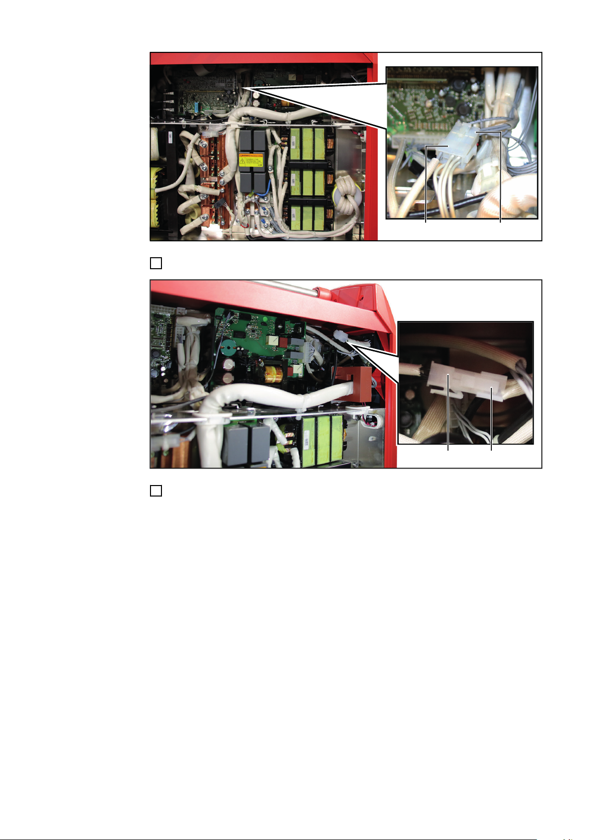
(11)
(13)
Connect the 8-pin socket from cable harness 02 (11) to the 8-pin plug (13)
(10)
(14)
17
Connect the 2-pin plug from cable harness 01 (10) to the cable harness already
18
present in the device (14)
58

(15) (15)
Fix the installed cables to the existing cables using the cable ties (15)
(1)
(2)
(1)
(1) (1) (1)
19
Insert the side panel (2) in its original
20
position
Secure the side panel (2) with 5 TX25
21
screws (1)
Tightening torque 3.5 Nm (2.58 ft
lb)
EN-US
59

Installing the OPT/i WF Sense Lead in the wirefee-
(1)
(1)
(2)
(1) (1)
(3)
TOP
der / SB 500i
Installing the
OPT/i WF Sense
Lead
Disconnect the device from all other
1
system components
Undo the 4 TX20 screws (1)
2
Remove the cover (2)
3
Select the feedthrough (3) for the next
4
step
If there is already a coolant connection
at the position of the feedthrough (3),
select one of the feedthroughs on the
opposite side of the device
Use a knife to cut away the film along
5
the marked outline of the feedthrough
(3)
Use a tool to apply pressure to the
6
center of the feedthrough (3) until the
cover plate behind the film breaks
through and falls off
60
During the following step, make sure
7
that the „TOP“ marking on the Sense
Lead plug points upwards after installation

(4)(5) (5)
Insert the Sense Lead plug (4) into the
(6)
(6)(4)
(7)
8
device
- The „TOP“ marking must point upwards
Secure the Sense Lead plug with the
9
2 TX20 screws (5)
- Tightening torque 2 Nm (1.48 ft
lb)
EN-US
Slide the protective cover (6) over the Sense Lead plug (4) and close it
10
Connect the 4-pin cable from the Sense Lead plug to the cable harness (7)
11
- On PAP devices, the cable harness (7) is located on the opposite side of the device
61

(8)
Connect the second cable from the Sense Lead plug to the flat tab (8)
(9)
12
- On PAP devices, the flat tab (8) is located on the right-hand side of the device
62
Fix the installed cables with the cable tie (9)
13
- The factory installation of the cables in the devices may vary
- In any case, fix the newly added cables with one or more cable ties so that these cables do not protrude from the device and do not chafe anywhere

(1)
(1)
(2)
(1) (1)
Place the cover (2) in its original posi-
14
tion
Secure the cover (2) with 4 TX20
15
screws (1)
- Tightening torque 2 Nm (1.48 ft
lb)
EN-US
63

64

Power source, wirefeeder, SB 500i
produced before 01/01/2022
65

66

Installing the OPT/i TPS Sense Lead in the power
(1)
(2)
(1)
(1) (1) (1)
Multivoltage Powersource
(3) (4) (3)
source
Installing the
OPT/i TPS Sense
Lead
Loosen the 5 TX25 screws (1)
1
Remove the side panel (2)
2
EN-US
Loosen the 2 TX25 screws (3) on the current instrument shunt (4)
3
67

(5) (6) (5)
Loosen the 2 TX25 screws (5) on the mounting plate (6)
(7) (8)
4
- The mounting plate is no longer needed
Select the right mounting plate from the scope of supply of OPT/i TPS Conversion
5
Sense Lead :
- Mounting plate (7) for multivoltage power sources
- Mounting plate (8) for all other power sources
68

(10)(7)
(10) (10)(9)
Screw the 3 plastic spacers (9) onto the positions (10) on the selected mounting pla-
(11)
(9)
(9)
(9)
(11)
(12)
(13)
(13)
6
te (7) / (8)
- Tightening torque: 0.5 Nm (0.36 ft lb)
EN-US
Put the Sense Lead PC board (11) on the plastic spacers (9)
7
- The Sense Lead PC board (11) must lock in place on the plastic spacers (9)
Connect the 4-pin plug from cable harness 01 (12) to the Sense Lead PC board (11)
8
Connect the two 2-pin plugs from cable harness 02 (13) to the Sense Lead PC board
9
(11)
69

(5) (7) (5)
Secure the mounting plate (7) / (8) including the previously fitted Sense Lead PC
Multivoltage Powersource
(3) (4) (3)
10
board with the 2 TX25 screws (5)
- Tightening torque 3.5 Nm (2.58 ft lb)
70
Secure the current instrument shunt (4) with the 2 TX25 screws (3)
11
- Tightening torque 3.5 Nm (2.58 ft lb)

(A)
(B)
(A)
(B)
Disconnect the existing 24-pin plug
(14)
12
Connect the supplied Device ID cable harness to the 24-pin plug as follows:
13
- Cable A5 - X14: 22 CFM to X14 Pin 22 (A)
- Cable A5 - X14: 10 CFM GND to X14 Pin 10 (B)
Connect the 24-pin plug in its original position
14
EN-US
Connect the 3-pin plug (14) from cable harness 01 to socket X16 in the power
15
source
71

(15)
Disconnect the 8-pin plug (15) from the PC board in the power source (from socket
(13)
(15)
16
X12)
Connect the 8-pin plug from cable harness 02 in the original position of the 8-pin
17
plug (15) in the power source (to socket X12)
Connect the 8-pin socket from cable harness 02 (13) to the 8-pin plug (15)
18
72

(16)
(17)
(18)
(17)
Remove the cover (16)
(19)
19
Loosen the 2 TX20 screws (17)
20
Pull the plug (18) backwards out of the rear of the device
21
EN-US
Select cable harness 03 (19) from the scope of supply of OPT/i TPS Conversion
22
Sense Lead [see section Scope of supply OPT/i TPS Conversion Sense Lead
(for power sources) on page 48]
73

(23)
(22) (18)
(20)
(21)
(16)
(17)
(18)
(17)
Insert the sockets (20) and (21) of cable harness 03 into holes 2 (22) and 4 (23) of
23
the plug (18)
- The cables of the sockets (20) and (21) are labeled 2 and 4
- Insert socket 2 into hole 2
- Insert socket 4 into hole 4
Insert the plug (18) into the rear of the device
24
Tighten the 2 TX20 screws (17)
25
Tightening torque 2 Nm (1.48 ft lb)
Slide the cover (16) over the connection (18) and close it
26
74

(12)
(19)
Connect the 2-pin plug from cable harness 01 (12) to the previously installed cable
(24) (24)
(1)
(2)
(1)
(1) (1) (1)
27
harness 03 (19)
EN-US
Fix the installed cables to the existing cables using the cable ties (24)
28
Insert the side panel (2) in its original
29
position
Secure the side panel (2) with 5 TX25
30
screws (1)
Tightening torque 3.5 Nm (2.58 ft
lb)
75

Installing the OPT/i WF Sense Lead in the wirefee-
(1)
(1)
(2)
(1) (1)
(3)
TOP
der / SB 500i
Installing the
OPT/i WF Sense
Lead
Disconnect the device from all other
1
system components
Undo the 4 TX20 screws (1)
2
Remove the cover (2)
3
Select the feedthrough (3) for the next
4
step
If there is already a coolant connection
at the position of the feedthrough (3),
select one of the feedthroughs on the
opposite side of the device
Use a knife to cut away the film along
5
the marked outline of the feedthrough
(3)
Use a tool to apply pressure to the
6
center of the feedthrough (3) until the
cover plate behind the film breaks
through and falls off
76
During the following step, make sure
7
that the „TOP“ marking on the Sense
Lead plug points upwards after installation

(4)(5) (5)
Insert the Sense Lead plug (4) into the
(6)
(6)(4)
(7)
8
device
- The „TOP“ marking must point upwards
Tighten the Sense Lead plug with 2
9
TX20 screws (5)
- Tightening torque 2 Nm (1.48 ft
lb)
EN-US
Slide the protective cover (6) over the Sense Lead plug (4) and close it
10
Select cable harness 03 (7) from the scope of supply of OPT/i TPS Conversion Sen-
11
se Lead [see section Scope of supply OPT/i TPS Conversion Sense Lead (for
power sources) on page 48]
77

(10)
(11)
(12)
(8)
(9)
(7)
Insert the pins (8) and (9) of cable harness 03 into holes 2 (11) and 4 (10) of the plug
(7)
12
(12)
- On PAP devices, the plug (12) is located on the opposite side of the device
- The cables of the pins (8) and (9) are labeled 2 and 4
- Insert pin 2 into hole 2
- Insert pin 4 into hole 4
78
Connect the 4-pin cable from the Sense Lead plug to the cable harness (7)
13

(13)
Connect the second cable from the Sense Lead plug to the flat tab (13)
(14)
14
- On PAP devices, the flat tab (13) is located on the right-hand side of the device
EN-US
Fix the installed cables with the cable tie (14)
15
- The factory installation of the cables in the devices may vary
- In any case, fix the newly added cables with one or more cable ties so that these cables do not protrude from the device and do not chafe anywhere
79

(1)
(1)
(2)
(1) (1)
Place the cover (2) in its original posi-
16
tion
Secure the cover (2) with 4 TX20
17
screws (1)
- Tightening torque 2 Nm (1.48 ft
lb)
80

EN-US
81

82

EN-US
83

Fronius International GmbH
Froniusstraße 1
4643 Pettenbach
Austria
contact@fronius.com
www.fronius.com
Under www.fronius.com/contact you will find the adresses
of all Fronius Sales & Service Partners and locations.
spareparts.fronius.com
SPAREPARTS
ONLINE
 Loading...