


Fronius prints on elemental chlorine free paper (ECF) sourced from certified sustainable forests (FSC).
/ Perfect Charging / Perfect Welding / Solar Energy
OPT/i TPSi C PushPull
Installationsanleitung
DE
Installation instructions
EN
Instructions d'installation
FR
42,0410,2092 009-07032022


Allgemeines
DE
Sicherheit
WARNUNG!
Gefahr durch Fehlbedienung und fehlerhaft durchgeführte Arbeiten.
Schwere Personen- und Sachschäden können die Folge sein.
Alle in diesem Dokument beschriebenen Arbeiten und Funktionen dürfen nur von
▶
technisch geschultem Fachpersonal ausgeführt werden.
Dieses Dokument vollständig lesen und verstehen.
▶
Sämtliche Sicherheitsvorschriften und Benutzerdokumentationen dieses Gerätes
▶
und aller Systemkomponenten lesen und verstehen.
WARNUNG!
Gefahr durch elektrischen Strom.
Schwere Personen- und Sachschäden können die Folge sein.
Vor Beginn der Arbeiten alle beteiligten Geräte und Komponenten ausschalten und
▶
von Stromnetz trennen.
Alle beteiligten Geräte und Komponenten gegen Wiedereinschalten sichern.
▶
Nach dem Öffnen des Gerätes mit Hilfe eines geeigneten Messgerätes sicherstel-
▶
len, dass elektrisch geladene Bauteile (beispielsweise Kondensatoren) entladen
sind.
WARNUNG!
Gefahr durch unzureichende Schutzleiter-Verbindungen.
Schwere Personen- und Sachschäden können die Folge sein.
Die Gehäuse-Schrauben stellen eine geeignete Schutzleiter-Verbindung für die Er-
▶
dung des Gehäuses dar.
Die Gehäuse-Schrauben dürfen keinesfalls durch andere Schrauben ohne zu-
▶
verlässige Schutzleiter-Verbindung ersetzt werden.
WARNUNG!
Gefahr durch heiße Systemkomponenten und / oder Betriebsmittel.
Schwere Verbrennungen und Verbrühungen können die Folge sein.
Vor Beginn der Arbeiten alle heißen Systemkomponenten und / oder Betriebsmittel
▶
auf +25 °C / +77 °F abkühlen lassen (beispielsweise Kühlmittel, wassergekühlte
Systemkomponenten, Antriebsmotor des Drahtvorschubes, ...).
Geeignete Schutzausrüstung tragen (beispielsweise hitzebeständige Schutzhand-
▶
schuhe, Schutzbrille, ...), wenn ein Abkühlen nicht möglich ist.
3

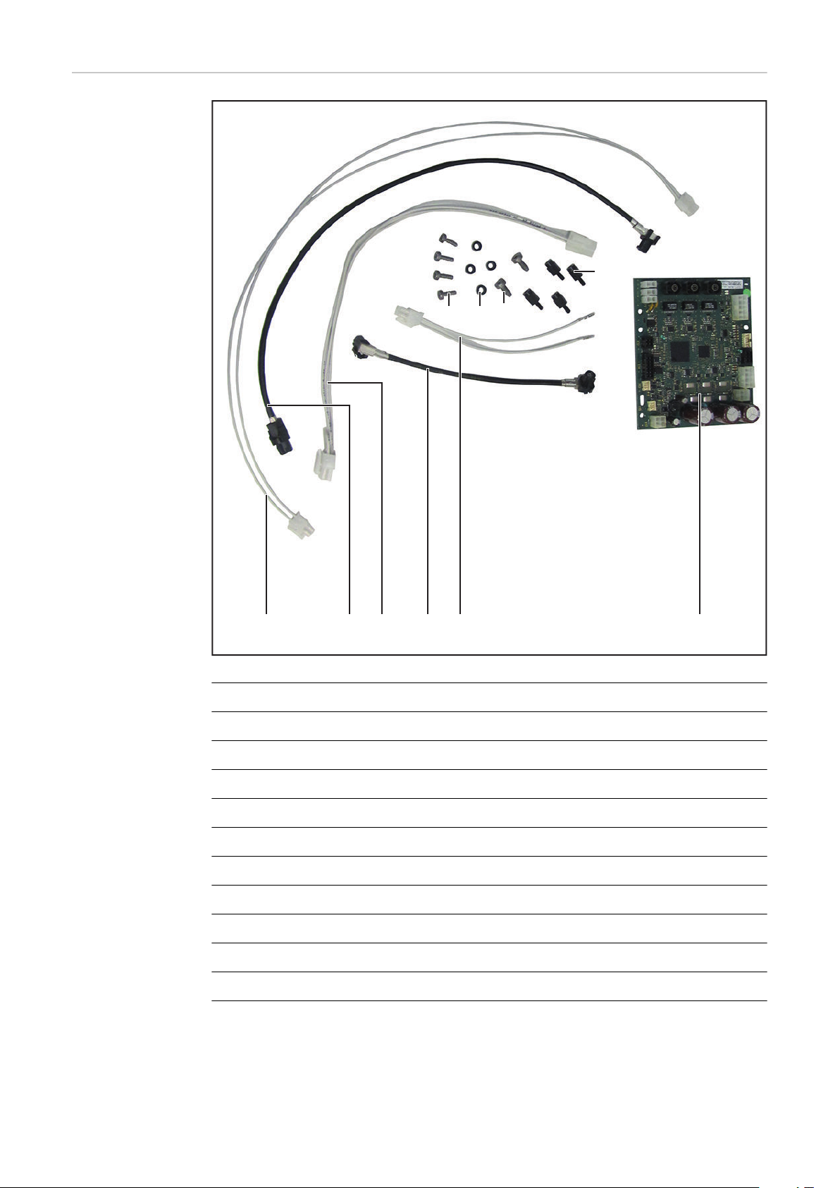
Lieferumfang
(1) (2) (3) (4)
(5)
(6) (7)
(10)
(8)
(9)
(1) Kabelbaum
(2) HSD-Leitung 500 mm
(3) Kabelbaum
(4) HSD-Leitung gewinkelt
(5) Kabelbaum
(6) 4 Schrauben M4 x 12 TX20
(7) 4 Distanzrollen M4
(8) 2 Schrauben M5 x 12 TX25
(9) 4 Distanzen
(10) Print SR63C
(11) Schaltplan (nicht abgebildet)
4

Erforderliches
Werkzeug
- Torx Schraubendreher TX 20 und TX 25
- Sechskant-Steckschlüssel SW 8 mm
- Seitenschneider
für Kabelbinder
- Schlitz-Schraubendreher klein (z.B. A 0,4 x 2,5)
für Schutzhülle HSD-Stecker
DE
5

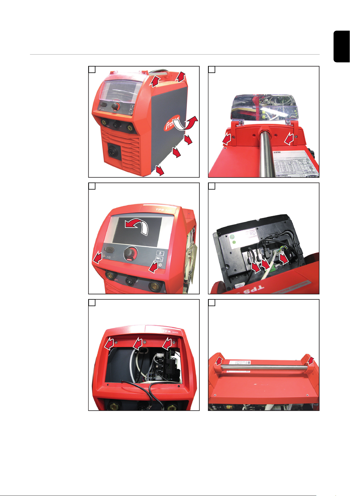
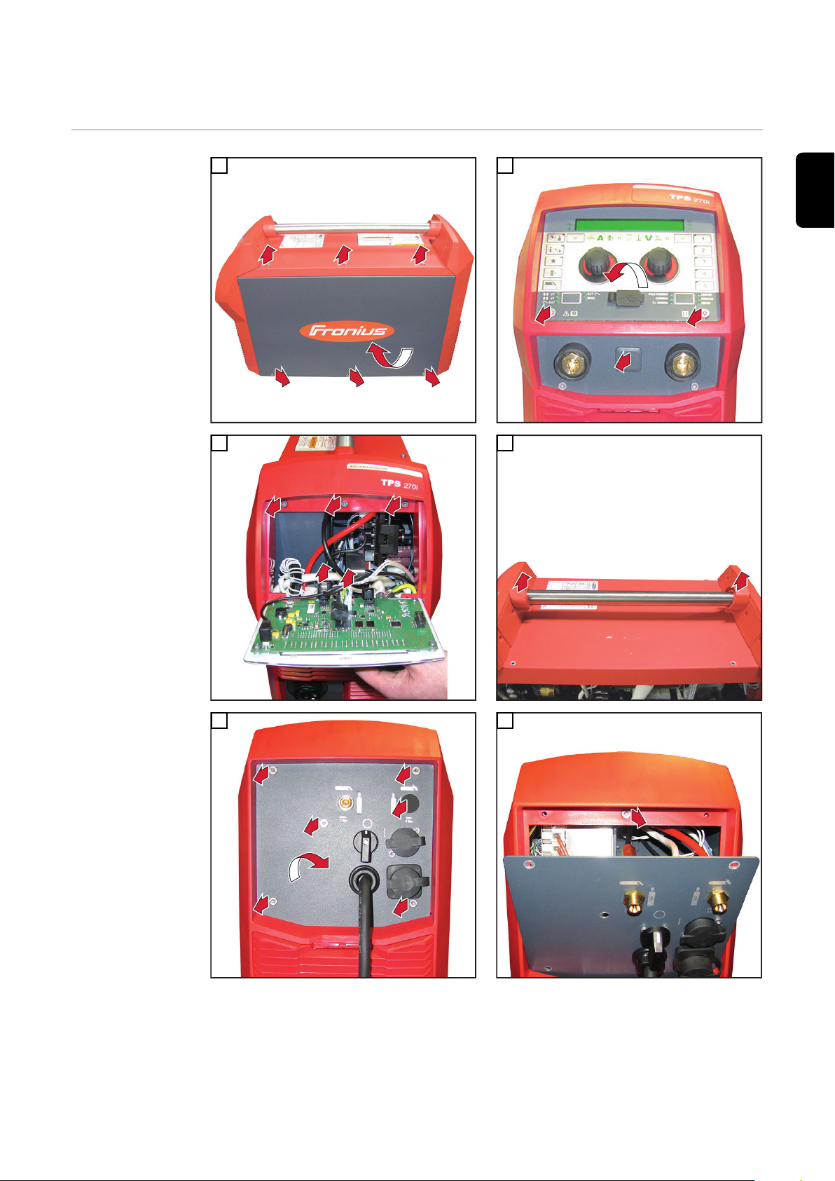
OPT/i TPS 270i C PushPull einbauen
1
1
1
3
2
2
2
2
3
1
1
3
3
3
1
2
1
1
1
1
1
1
1
2
3
1
Vorbereitende
Tätigkeiten
1
3
2
4
5
6
6

2
1
1
3
7
2
2
1
1
3
4
1
1
1
2
3
4
4
1
3
2
5
1
1
2
1
2
1
1
8
DE
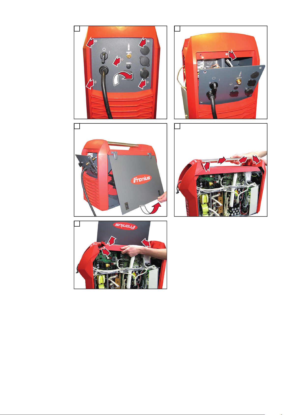
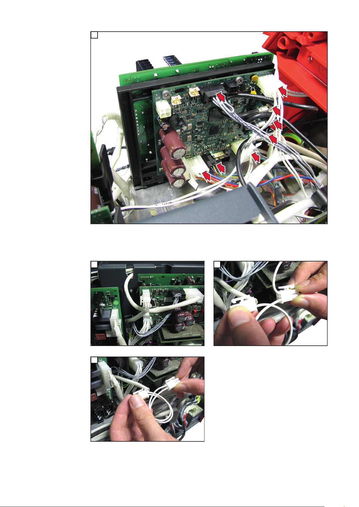
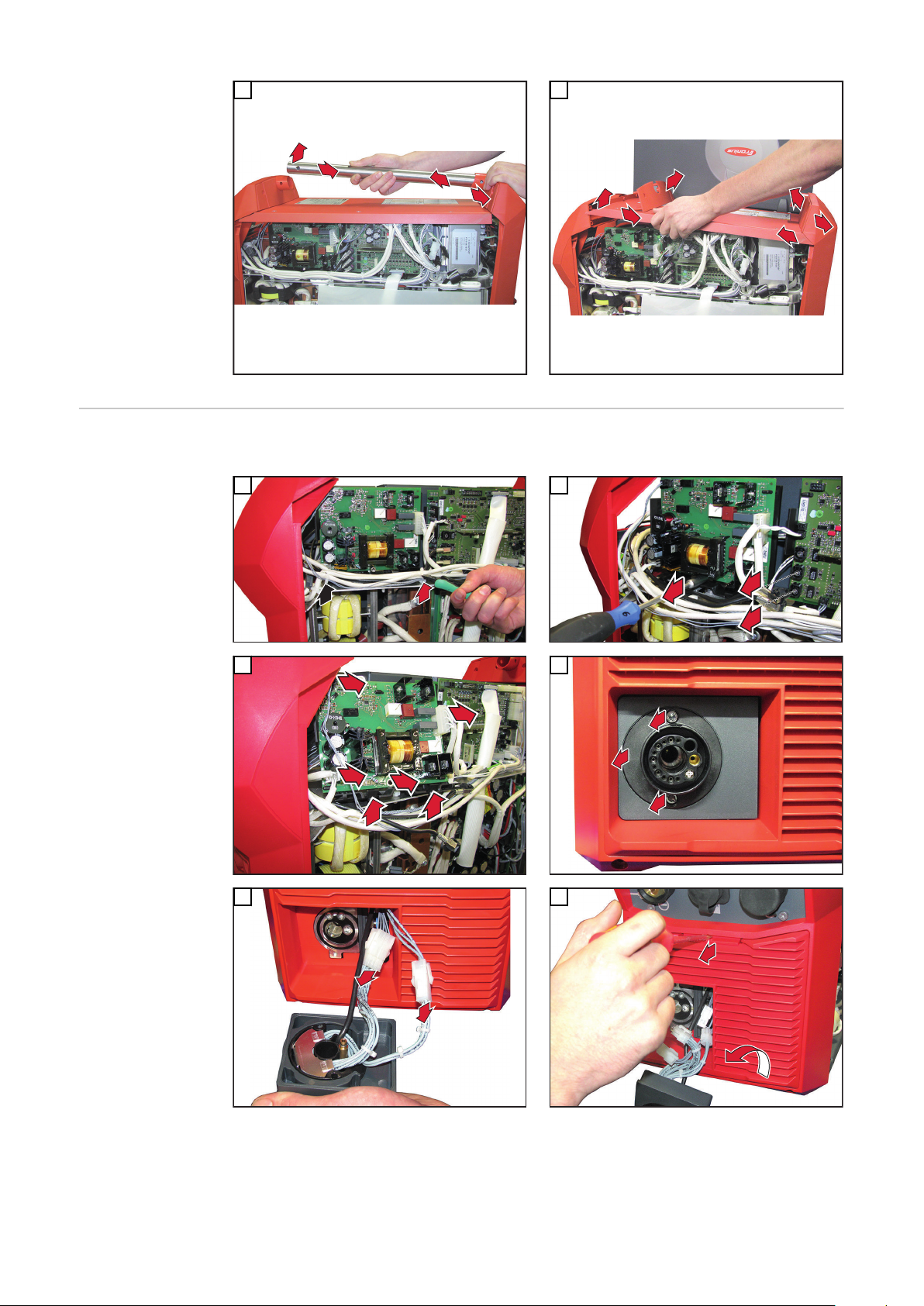
PushPull-Leitungen und Print
SR63C installieren
Beim Herstellen der elektrischen Verbindungen, den beiliegenden Schaltplan beachten.
1
3
2
4
5
6
7

2
1
7
1
2
2
1
2
1
1
2
1
2
1
8
9
11 12
10
13
8

4
5
2
X17
X1
1
1
3
1
SR63C provided
3
3
2
**
* *
*
1
3
*
11,5
14
1
X26
1
2
3
4
FSCFSC
X9 (POE)
DE
15
16
WARNUNG!
Gefahr durch einen elektrischen Schlag.
Ein elektrischer Schlag kann tödlich sein.
Um einen elektrischen Schlag zu verhindern, zwischen Kabel und Print einen Min-
▶
destabstand von > 8 mm (> 0.31 in) einhalten!
9

1
3
4
5
6
5
1
2*
**
11
> 8 mm
> 0.31 in.
17
1
2
1
3
18
19
10

1
*
2
2
**
**
20
1
4
3
4
2
1
3
2
2
2
2
3
3
1
3
**
******
** ** **
13
1
**
**
13
DE
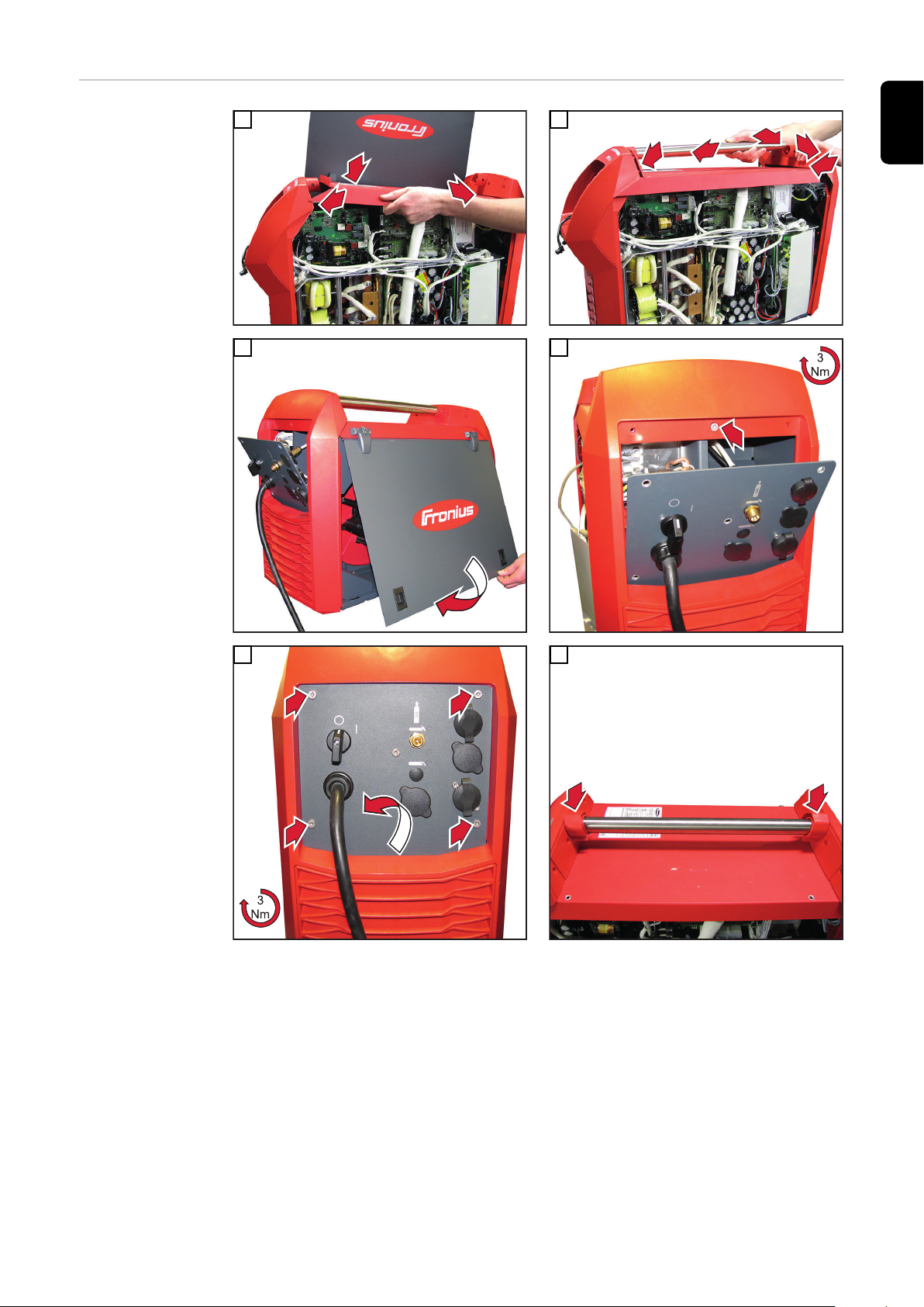
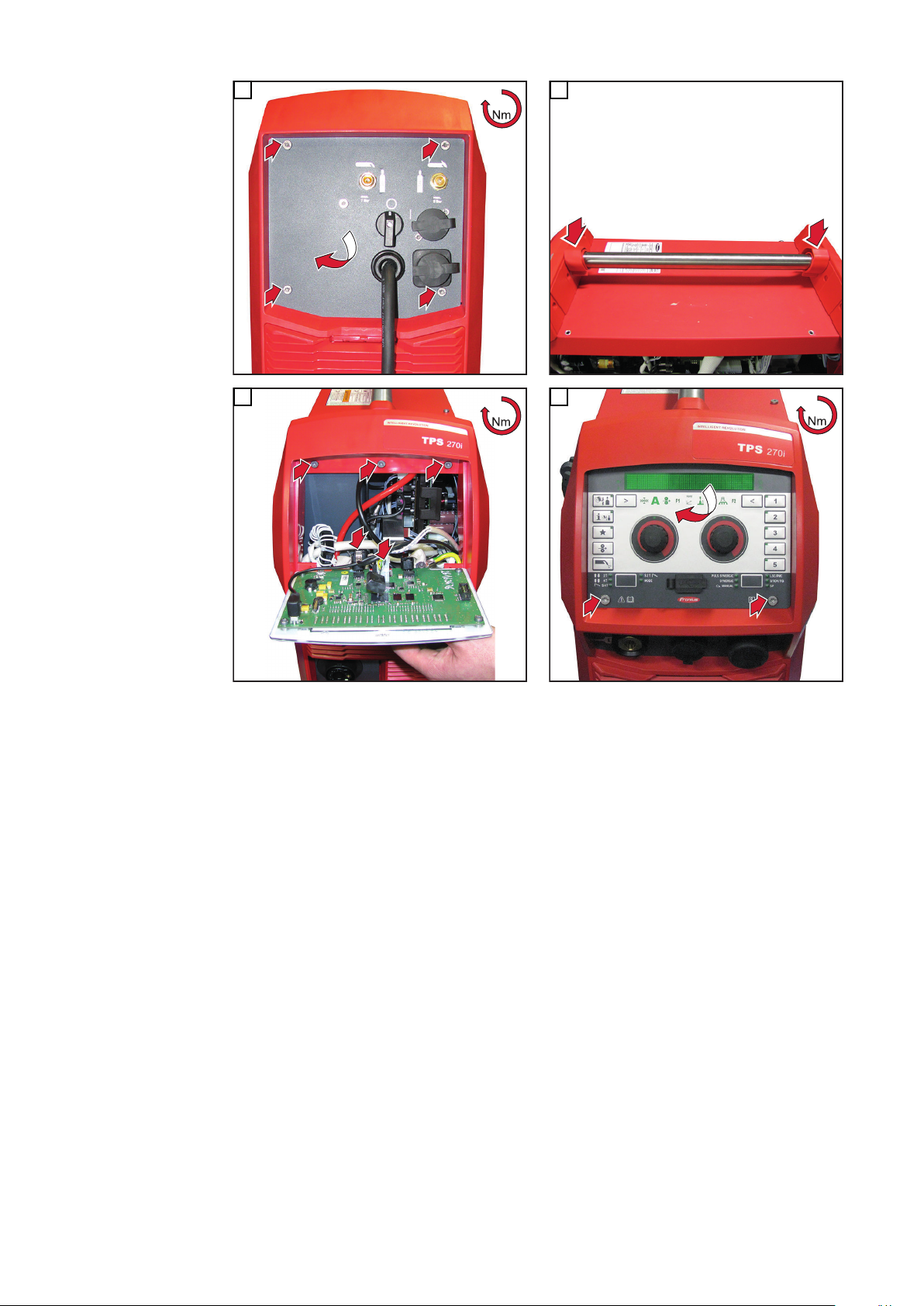
Abschließende
Tätigkeiten
1
3
2
4
11

1
**
** **
****
13
2
2
2
2
5
1
1
2
3
1
1
1
**
** ** **
13
1
2
2
**
11,5
****
6
7
8
12
OPT/i TPS 320i C PushPull einbauen
2
2
3
1
1
1
1
1
1
1
2
1
2
3
1
1
1
1
1
DE
Vorbereitende
Tätigkeiten
1
3
2
4
5
6
13
2
1
1
1
1
1
7
1
1
2
3
1
1
2
1
3
8
11
9
10
14

PushPull-Leitun-
1
1
1
2
3
4
4
1
3
2
5
4
5
7
6
1
2
3
1
1
2
1
2
1
1
1
1
3
2
gen und Print
SR63C installieren
Beim Herstellen der elektrischen Verbindungen, den beiliegenden Schaltplan beachten.
1
2
DE
3
5
4
nur Variante SMB 5000
6
7
8
15

2
1
1
2
1
VAC
11
1
1
2
1
2
9
10
12
13
Nur Variante SMB 5000 (bis Seriennummer 26043380):
16

FE-Ring
Position
14
FSC
FE-Ring
Position
**
33
**
**
1
4
5
6
7
8
3
2
DE
nur Variante SMB 5000
15
nur Variante SMB 5000
17
1
2
3
4
5
6
7
8
16
1
nur Variante SMB 5000
Nur Variante SMB 2700 (ab Seriennummer 26043380):
17
nur Variante SMB 2700
19
18
nur Variante SMB 2700
18
nur Variante SMB 2700

4
5
2
X17
X1
1
1
3
1
SR63C provided
3
3
2
**
* *
*
1
3
*
11,5
20
1
X26
1
2
3
4
FSC
nur Variante SMB 2700
21
DE
22
nur Variante SMB 2700
nur Variante SMB 2700
Beide Varianten:
WARNUNG!
Gefahr durch einen elektrischen Schlag.
Ein elektrischer Schlag kann tödlich sein.
Um einen elektrischen Schlag zu verhindern, zwischen Kabel und Print einen Min-
▶
destabstand von > 8 mm (> 0.31 in) einhalten!
19

1
3
4
5
6
5
1
2*
**
11
> 8 mm
> 0.31 in.
23
1
*
2
3
**
**
1
2
1
3
2
2
1
*
**
**
24
25
26
27
20
Abschließende
2
3
1
4
2
1
5
3
1
*
1
**
2
2
2
2
1
*
** **
** **
1
1
Tätigkeiten
1
2
DE
3
5
4
6
21

1
1
1
*
** ** **
7
1
2
3
1
2
2
*
**
**
1
1
*
** **
2
2
*
1
3
3
3
**
**
**
**
**
8
11
9
10
22

Sicherheitstechnische Überprüfung
Allgemeines Sicherheitstechnische Überprüfung gemäß den entsprechenden nationalen und regiona-
len Bestimmungen durchführen:
- nach Veränderung
- nach Ein- und Umbauten
- nach Reperatur, Pflege und Wartung
- mindestens alle zwölf Monate
Im DownloadCenter unter „Sicherheit, Umwelt & Gesundheit“ - „Basisinformationen“ finden Sie die folgende PDF-Datei:
- Die neueste Version der Arbeitsanweisung „Sicherheitstechnische Überprüfung von
Lichtbogen-Schweisseinrichtungen (AA-PMÜ-01)“.
DE
23

General
Safety
WARNING!
Danger from incorrect operation and work that is not carried out properly.
This can result in serious personal injury and damage to property.
All the work and functions described in this document must only be carried out by
▶
technically trained and qualified personnel.
Read and understand this document in full.
▶
Read and understand all safety rules and user documentation for this device and all
▶
system components.
WARNING!
Danger from electrical current.
This can result in serious personal injury and damage to property.
Before starting work, switch off all devices and components involved and disconnect
▶
them from the grid.
Secure all devices and components involved so they cannot be switched back on.
▶
After opening the device, use a suitable measuring instrument to check that electri-
▶
cally charged components (such as capacitors) have been discharged.
WARNING!
Danger due to insufficient ground conductor connection.
This can result in serious personal injury and damage to property.
The housing screws provide a suitable ground conductor connection for grounding
▶
the housing.
The housing screws must not under any circumstances be replaced by other screws
▶
without a reliable ground conductor connection.
WARNING!
Danger due to hot system components and/or equipment.
Can result in serious burns or scalding.
Before starting work, allow all hot system components and/or equipment to cool to
▶
+25°C/+77°F (e.g., coolant, water-cooled system components, wirefeeder drive motor, etc.)
Wear suitable protective equipment (e.g., heat-resistant gloves, safety goggles, etc.)
▶
if cooling down is not possible.
24

Scope of supply
(1) (2) (3) (4)
(5)
(6) (7)
(10)
(8)
(9)
EN
(1) Cable harness
(2) HSD cable, 500 mm
(3) Cable harness
(4) HSD cable, angled
(5) Cable harness
(6) 4 screws M4 x 12 TX20
(7) 4 spacer rollers M4
(8) 2 screws M5 x 12 TX25
(9) 4 spacers
(10) SR63C PC board
(11) Circuit diagram (not shown)
25

Tools required - Torx screwdriver, TX20 and TX25
- Hexagonal socket wrench, 8 mm
- Side cutter
for cable ties
- Slotted screwdriver small (e.g. A 0,4 x 2,5)
for protective cover HSD connector
26
Installing the OPT/i TPS 270i C PushPull
1
1
1
3
2
2
2
2
3
1
1
3
3
3
1
2
1
1
1
1
1
1
1
2
3
1
Preparations
1
2
EN
3
4
5
6
27
2
1
1
3
7
2
2
1
1
3
4
1
1
1
2
3
4
4
1
3
2
5
1
1
2
1
2
1
1
8
Installing the
PushPull leads
and SR63C PC
board
Follow the enclosed circuit diagram when establishing the electrical connections.
1
3
2
4
5
28
6

2
1
7
1
2
2
1
2
1
1
2
1
2
1
8
EN
9
11 12
10
13
29

4
5
2
X17
X1
1
1
3
1
SR63C provided
3
3
2
**
* *
*
1
3
*
11,5
14
1
X26
1
2
3
4
FSCFSC
X9 (POE)
15
16
WARNING!
Risk of electric shock.
An electric shock can be fatal.
To prevent an electric shock, keep a minimum distance of > 8 mm (> 0.31 in) bet-
▶
ween the cable and the PC board!
30

1
3
4
5
6
5
1
2*
**
11
> 8 mm
> 0.31 in.
17
1
2
1
3
EN
18
19
31

1
*
2
2
**
**
20
1
4
3
4
2
1
3
2
2
2
2
3
3
1
3
**
******
** ** **
13
1
**
**
13
And finally...
1
3
2
4
32

1
**
** **
****
13
2
2
2
2
5
1
1
2
3
1
1
1
**
** ** **
13
1
2
2
**
11,5
****
6
EN
7
8
33

Installing the OPT/i TPS 320i C PushPull
2
2
3
1
1
1
1
1
1
1
2
1
2
3
1
1
1
1
1
Preparations
1
3
2
4
5
6
34

2
1
1
1
1
1
7
1
1
2
3
1
1
2
1
3
8
EN
11
9
10
35

Installing the
1
1
1
2
3
4
4
1
3
2
5
4
5
7
6
1
2
3
1
1
2
1
2
1
1
1
1
3
2
PushPull leads
and SR63C PC
board
Follow the enclosed circuit diagram when establishing the electrical connections.
1
2
3
5
4
SMB 5000 version only
6
7
36
8

2
1
1
2
1
VAC
11
1
1
2
1
2
9
10
EN
12
13
SMB 5000 version only (up to serial number 26043380):
37

FE-Ring
Position
14
FSC
FE-Ring
Position
**
33
**
**
1
4
5
6
7
8
3
2
SMB 5000 version only
15
SMB 5000 version only
38

1
2
3
4
5
6
7
8
16
1
EN
SMB 5000 version only
SMB 2700 version only (from serial number 26043380):
17
SMB 2700 version only
19
18
SMB 2700 version only
SMB 2700 version only
39

4
5
2
X17
X1
1
1
3
1
SR63C provided
3
3
2
**
* *
*
1
3
*
11,5
20
1
X26
1
2
3
4
FSC
SMB 2700 version only
21
22
SMB 2700 version only
SMB 2700 version only
Both versions:
WARNING!
Risk of electric shock.
An electric shock can be fatal.
To prevent an electric shock, keep a minimum distance of > 8 mm (> 0.31 in) bet-
▶
ween the cable and the PC board!
40

1
3
4
5
6
5
1
2*
**
11
> 8 mm
> 0.31 in.
23
1
*
2
3
**
**
1
2
1
3
2
2
1
*
**
**
EN
24
25
26
27
41

And finally...
2
3
1
4
2
1
5
3
1
*
1
**
2
2
2
2
1
*
** **
** **
1
1
1
2
3
5
4
6
42

1
1
1
*
** ** **
7
1
2
3
1
2
2
*
**
**
1
1
*
** **
2
2
*
1
3
3
3
**
**
**
**
**
8
EN
11
9
10
43

Safety Inspections
General A safety inspection must be carried out according to the relevant national and local regu-
lations:
- after any changes are made
- after any additional parts are installed, or after any conversions
- after repair, care and maintenance
- and at least once every twelve months
You can find the following PDF file in the DownloadCenter under "Safety, Environment &
Health" - "Basic information":
- The latest version of the "Safety inspections for arc welding and cutting systems"
work instruction (AA-PMÜ-01).
44

Généralités
Sécurité
AVERTISSEMENT!
Danger dû à une erreur de manipulation et d'erreur en cours d'opération.
Cela peut entraîner des dommages corporels et matériels graves.
Toutes les fonctions et tous les travaux décrits dans le présent document doivent
▶
uniquement être exécutés par du personnel techniquement qualifié.
Ce document doit être lu et compris dans son intégralité.
▶
Lire et comprendre toutes les consignes de sécurité et la documentation utilisateur
▶
de cet appareil et de tous les composants périphériques.
AVERTISSEMENT!
Risque d'électrocution.
Cela peut entraîner des dommages corporels et matériels graves.
Avant d'entamer les travaux, déconnecter tous les appareils et composants con-
▶
cernés et les débrancher du réseau électrique.
S'assurer que tous les appareils et composants concernés ne peuvent pas être re-
▶
mis en marche.
Après ouverture de l'appareil, s'assurer, à l'aide d'un appareil de mesure approprié,
▶
que les composants à charge électrique (condensateurs, par ex.) sont déchargés.
AVERTISSEMENT!
FR
Danger en cas de connexions insuffisantes des conducteurs de terre.
Cela peut entraîner des dommages corporels et matériels graves.
Les vis du boîtier constituent une connexion de conducteur de terre appropriée pour
▶
la mise à la terre du corps de l'appareil.
Les vis du boîtier ne doivent en aucun cas être remplacées par d'autres vis qui n'off-
▶
riraient pas ce type de connexion à la terre autorisée.
AVERTISSEMENT!
Danger en cas de contact avec les composants périphériques et/ou l'équipement.
Cela peut entraîner de graves brûlures.
Avant d'entamer les travaux, laisser refroidir tous les composants périphériques
▶
et/ou l'équipement chauds à +25 °C / +77 °F (par ex. réfrigérant, composants
périphériques refroidis à l'eau, moteur d'entraînement du dévidoir, ...).
Porter un équipement de protection adapté (par ex. gants de protection résistant à la
▶
chaleur, lunettes de protection, ...) si le refroidissement n'est pas possible.
45
Contenu de la liv-
(1) (2) (3) (4)
(5)
(6) (7)
(10)
(8)
(9)
raison
(1) Faisceau de câbles
(2) Câble haut débit 500 mm
(3) Faisceau de câbles
(4) Câble haut débit incliné
(5) Faisceau de câbles
(6) 4 vis M4 x 12 TX20
(7) 4 rouleaux d‘écartement M4
(8) 2 vis M5 x 12 TX25
(9) 4 entretoises
(10) Circuit imprimé SR63C
(11) Schéma de câblage (non représenté)
46

Outillage requis - Tournevis Torx TX 20 et TX 25
- Clé Allen OC 8 mm
- Pince coupante
pour attaches-câbles
- Tournevis plat petit (par exemple A 0,4 x 2,5)
pour couvercle de protection du connecteur HSD
FR
47

Installer l'option PushPull OPT/i TPS 270i C
1
1
1
3
2
2
2
2
3
1
1
3
3
3
1
2
1
1
1
1
1
1
1
2
3
1
Opérations
préparatoires
1
3
2
4
5
6
48

2
1
1
3
7
2
2
1
1
3
4
1
1
1
2
3
4
4
1
3
2
5
1
1
2
1
2
1
1
8
FR
Installer les
câbles PushPull
et le circuit imprimé SR63C
Se reporter au schéma de connexions fourni pour effectuer les raccordements électriques.
1
3
2
4
5
6
49

2
1
7
1
2
2
1
2
1
1
2
1
2
1
8
9
11 12
10
13
50

4
5
2
X17
X1
1
1
3
1
SR63C provided
3
3
2
**
* *
*
1
3
*
11,5
14
1
X26
1
2
3
4
FSCFSC
X9 (POE)
FR
15
16
AVERTISSEMENT!
Danger en cas de décharge électrique.
Une décharge électrique peut être mortelle!
Pour éviter une décharge électrique, maintenir un espace minimal de > 8 mm (>
▶
0.31 in) entre le câble et le circuit imprimé.
51

1
3
4
5
6
5
1
2*
**
11
> 8 mm
> 0.31 in.
17
1
2
1
3
18
19
52

1
*
2
2
**
**
20
1
4
3
4
2
1
3
2
2
2
2
3
3
1
3
**
******
** ** **
13
1
**
**
13
FR
Étapes finales
1
3
2
4
53
1
**
** **
****
13
2
2
2
2
5
1
1
2
3
1
1
1
**
** ** **
13
1
2
2
**
11,5
****
6
7
8
54

Installer l'option PushPull OPT/i TPS 320i C
2
2
3
1
1
1
1
1
1
1
2
1
2
3
1
1
1
1
1
Préparation
1
3
2
FR
4
5
6
55

2
1
1
1
1
1
7
1
1
2
3
1
1
2
1
3
8
11
9
10
56

Installer les
1
1
1
2
3
4
4
1
3
2
5
4
5
7
6
1
2
3
1
1
2
1
2
1
1
1
1
3
2
câbles PushPull
et le circuit imprimé SR63C
Se reporter au schéma de connexions fourni pour effectuer les raccordements électriques.
1
2
FR
3
5
4
uniquement variante SMB 5000
6
7
8
57

2
1
1
2
1
VAC
11
1
1
2
1
2
9
10
12
13
Uniquement variante SMB 5000 (jusqu'au numéro de série 26043380) :
58
FE-Ring
Position
14
FSC
FE-Ring
Position
**
33
**
**
1
4
5
6
7
8
3
2
FR
uniquement variante SMB 5000
15
uniquement variante SMB 5000
59

1
2
3
4
5
6
7
8
16
1
uniquement variante SMB 5000
Uniquement variante SMB 2700 (à partir du numéro de série 26043380) :
17
uniquement variante SMB 2700
19
18
uniquement variante SMB 2700
60
uniquement variante SMB 2700

4
5
2
X17
X1
1
1
3
1
SR63C provided
3
3
2
**
* *
*
1
3
*
11,5
20
1
X26
1
2
3
4
FSC
uniquement variante SMB 2700
21
FR
22
uniquement variante SMB 2700
uniquement variante SMB 2700
Les deux variantes :
AVERTISSEMENT!
Danger en cas de décharge électrique.
Une décharge électrique peut être mortelle.
Pour éviter une décharge électrique, maintenir un espace minimal de > 8 mm (>
▶
0.31 in) entre le câble et le circuit imprimé.
61

1
3
4
5
6
5
1
2*
**
11
> 8 mm
> 0.31 in.
23
1
*
2
3
**
**
1
2
1
3
2
2
1
*
**
**
24
25
26
27
62

Étapes finales
2
3
1
4
2
1
5
3
1
*
1
**
2
2
2
2
1
*
** **
** **
1
1
1
2
FR
3
5
4
6
63

1
1
1
*
** ** **
7
1
2
3
1
2
2
*
**
**
1
1
*
** **
2
2
*
1
3
3
3
**
**
**
**
**
8
11
9
10
64

Contrôle technique de sécurité
Généralités Effectuer un contrôle technique de sécurité conformément aux dispositions nationales et
régionales en vigueur :
- après toute modification
- après installation ou transformation de l'appareil
- après toute opération de réparation, entretien et maintenance
- au moins tous les douze mois
Vous trouverez le fichier suivant dans le DownloadCenter sous « Sécurité, environnement et santé » :
- Nouvelle version des instructions de travail « Contrôle technique de sécurité des
systèmes de soudage dans le cadre des opérations de réparation et d'entretien (AAPMÜ-01) »
FR
65

66

FR
67

Fronius International GmbH
Froniusstraße 1
4643 Pettenbach
Austria
contact@fronius.com
www.fronius.com
Under www.fronius.com/contact you will find the adresses
of all Fronius Sales & Service Partners and locations.
spareparts.fronius.com
SPAREPARTS
ONLINE
 Loading...