


Fronius prints on elemental chlorine free paper (ECF) sourced from certified sustainable forests (FSC).
/ Perfect Charging / Perfect Welding / Solar Energy
OPT/i TPS Ext. Welding Release
OPT/i TPS C Ext. Welding Release
Installationsanleitung
DEEN-US
MIG/MAG-Stromquelle
Installation Instructions
MIG/MAG Power source
42,0410,2455 006-25022020

2

Allgemeines
(1) (2) (3)(4)(5)
(6)(7)(8)
(9)
DE
Sicherheit
Allgemeines
WARNUNG!
Ein elektrischer Schlag kann tödlich sein.
Vor Öffnen des Gerätes
► Netzschalter in Stellung - O - schalten
► Gerät vom Netz trennen
► ein verständliches Warnschild gegen Wiedereinschalten anbringen
► mit Hilfe eines geeigneten Messgerätes sicherstellen, dass elektrisch geladene Bau-
teile (z.B. Kondensatoren) entladen sind
WARNUNG!
Fehlerhaft durchgeführte Arbeiten können schwerwiegende Personen- und Sachschäden verursachen.
► Nachfolgend beschriebene Tätigkeiten dürfen nur von geschultem Fachpersonal
durchgeführt werden!
► Beachten Sie das Kapitel „Sicherheitsvorschriften“ in der Bedienungsanleitung der
Stromquelle und der Systemkomponenten.
HINWEIS!
Ist an den Stromquellen TPS 270i C und TPS 320i C die OPT/i TPS C Ext. Weld. Release vorhanden, kann die OPT/i TPS C PushPull nicht eingebaut werden!
WICHTIG! Die Einbau-Sets OPT/i TPS Ext. Weld. Release und OPT/i TPS C Ext. Weld.
Release dürfen nicht als Not-Stopp oder als Sicherheitsabschaltung verwendet werden!
Die Einbau-Sets dienen ausschließlich zur Schweiß-Freigabe.
Lieferumfang OPT/i TPS Ext. Weld. Release
(1) Abdeckung
(2) Print BRTSFMAG50 mit Halterung
(3) 2 Schrauben TX20
(4) Messing-Distanz M5 x 55 mm
(5) 2 Kabelbinder
(6) Anker für Kabelbinder
(7) Device-ID
(8) Kabelbaum
(9) Kabelbaum mit Buchse
3

OPT/i TPS C Ext. Weld. Release
(1) (2)
(3)(4)(5)(7) (6)
(1) Device-ID
(2) Kabelbaum mit Buchse
(3) Kabelbaum
(4) Print BRTSFMAG50
(5) 2 Schrauben TX20 4 x 8 mm
(6) 4 Kabelbinder
(7) 2 Schrauben TX20 4 x 12 mm
Erforderliche
Werkzeuge
- Torx Schraubendreher TX 25
- Torx Schraubendreher TX 20
- Steckschlüssel SW 8 mm
- Seitenschneider
4

OPT/i TPS Ext. Welding Release in TPS 320i - 600i
2
1
X13
SMB5000
1
3
2
X13
X3
2
3
einbauen
Vorbereitung Stromquelle ausschalten und vom Netz trennen
OPT/i TPS Ext.
Welding Release
einbauen
1
Rechten Seitenteil der Stromquelle entfernen
WICHTIG! Die Option OPT/i TPS Ext. Welding Release muss beim Einbauen vor dem
Print SMB5000 positioniert werden.
DE
E-Stopp-Bügel von X13 abstecken
4-poligen Stecker vom Kabelbaum aus
dem Lieferumfang an X13 anstecken
14-poligen Stecker von X3 abstecken
5

2 graue Einzelkabel vom Kabelbaum
4
5
4
X3
4
5
X9
6
6
X14
7
8
8
7
8
aus dem Lieferumfang gemäß Kabelaufdruck am 14-poligen Stecker an
den Pins 3 und 10 anstecken
14-poligen Stecker wieder an X3 anstecken
6-poligen Stecker vom Kabelbaum aus
dem Lieferumfang an X9 anstecken
nur bei MV-Geräten:
a) vorhandenes Kabel von X9 abstecken
b) 6-poligen Stecker vom Kabelbaum aus
dem Lieferumfang an X9 anstecken
c) das vorhandene Kabel am Kabelbaum
aus dem Lieferumfang anstecken
24-poligen Stecker von X14 abstecken
2 Kabel von der Device-ID gemäß Ka-
belaufdruck am 24-poligen Stecker an
den Pins 8 und 21 anstecken:
graues Kabel an X14/8
grünes Kabel an X14/21
6

24-poligen Stecker wieder an X14 an-
X14
10
9
9
10
11
13
14
11
12
X3
11
12
13
14
15
15
stecken
Kabelbaum mit Kabelbinder fixieren,
Kabelbinder ablängen
Print BRTSFMAG50 mit Halterung einschieben, bis die Verriegelung hörbar
einrastet
12-poligen Stecker vom Kabelbaum
am Print BRTSFMAG50 auf X3 anstecken
Kabelbaum mit Kabelbinder fixieren,
Kabelbinder ablängen
Messing-Distanz M5 x 55 mm aufschrauben
DE
Abdeckung entfernen
7
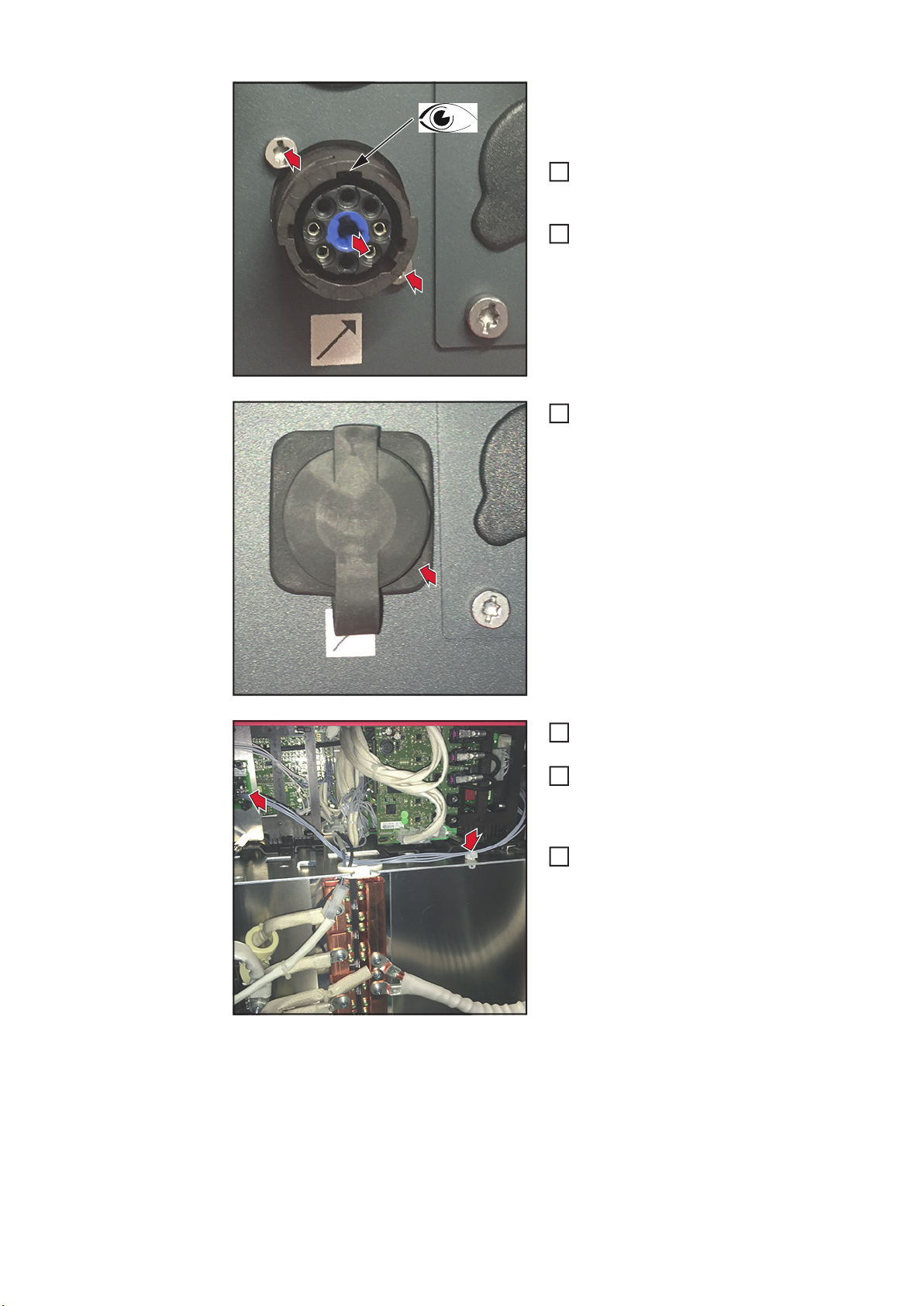
WICHTIG! Beim Einsetzen der Buchse da-
16
17
17
16
17
18
18
X1
19
20
19
20
21
rauf achten dass die Markierung „Top“ / die
breite Ausnehmung oben ist.
Buchse vom Kabelbaum mit Buchse
von innen nach außen in die Öffnung
einsetzen
Buchse mit 2 Schrauben TX20 fixieren
Abdeckung über der Buchse anbringen
Graues Kabel am Print BRTSFMAG50
auf X1 anstecken
Kabel mit Kabelbinder und Anker für
Kabelbinder fixieren, Kabelbinder ablängen
Rechten Seitenteil der Stromquelle
montieren
8

OPT/i TPS C Ext. Welding Release in TPS 270i C ein-
3
6 x TX25
1
2
4
5
6
7
3
2 x TX25
1
2
3
5
1
1
1
1
bauen
Vorbereitung Stromquelle ausschalten und vom Netz trennen
1
1 2
2
1
5
3 4
4
DE
3
2
6
5 x TX25
4
OPT/i TPS C Ext.
Welding Release
einbauen
1
Kabelbaum mit Buchse nahe beim
Gasschlauch nach vorne verlegen
9
WICHTIG! Beim Einsetzen der Buchse da-
4
2
4
4
4
3
3
4
2
3
4
5
5
6
6
6
8
7
6
7
8
rauf achten dass die Markierung „Top“ / die
breite Ausnehmung oben ist.
Buchse vom Kabelbaum mit Buchse
von innen nach außen in die Öffnung
einsetzen
Buchse mit 2 Schrauben TX20 4 x 12
mm fixieren
Rückseite mit 5 Schrauben TX25 fixieren
Abdeckung über der Buchse anbringen
Alle Kabel und Stecker vom Print
NT601 abstecken
Messingdistanz SW 8 mm entfernen
Print NT601 mit Halterung heraus neh-
men
10

Print BRTSFMAG50 an der Rückseite
11
9
10
10
9
10
11
14
14
12
13
12
14
15
12
13
14
15
16
16
der Halterung positionieren
Print BRTSFMAG50 mit 2 Schrauben
TX20 4 x 8 mm fixieren
Anzugsmoment = 1,5 Nm
10-poligen Stecker vom Kabelbaum
am Print BRTSFMAG50 anstecken
Die beiden Prints mit Halterung bis
zum Einrasten einschieben
Messingdistanz SW 8 mm montieren
Alle Kabel und Stecker am Print NT601
anstecken
6-poligen Stecker vom Print SMB2700
abstecken
DE
Das von der Rückseite kommende Kabel am Print BRTSFMAG50 anstecken
11

6-poligen Stecker mit dem Y-Stück
17
17
18
17
18
19
19
20
20
20
verbinden
Das 2. Ende vom Y-Stück am Print
SMB2700 anstecken
Den grauen Stecker abstecken und
entsorgen
Verbleibenden Stecker vom Kabelbaum anstecken
12

Die 2 grauen Einzelkabel vom Kabel-
21
22
21
21
22
21
22
23
23
23
23
2
baum zum Stecker X14 verlegen und
gemäß Kabelaufdruck bei X14/14 und
X14/15 dazustecken
Kabel der Device-ID an X14 anschließen:
grünes Kabel an X14/21
graues Kabel an X14/22
Kabel mit Kabelbinder fixieren, Kabelbinder ablängen
DE
Abschließende
Tätigkeiten
Bedienpanel mit 2 Schrauben TX25 an der Stromquelle montieren
1
Rechten Seitenteil der Stromquelle montieren
13

OPT/i TPS C Ext. Welding Release in TPS 320i C ein-
1
1
1
bauen
OPT/i TPS C Ext.
Welding Release
in TPS 320i C einbauen
Der Einbau der OPT/i TPS C Ext. Weld. Release in die TPS 320i C erfolgt gleich, wie der
Einbau in die TPS 270i C.
Einzig das Kabel vom Kabelbaum mit Buchse wird durch den vorhandenen Kabeltunnel
zur Vorderseite der Stromquelle verlegt:
Kabelbaum mit Buchse durch den Kabeltunnel nach vorne verlegen
Die folgenden Arbeitsschritte entsprechen denen der TPS 270i C, ab Seite 10, Arbeitsschritt 2.
14

Anschlussbelegung
DE
Anschlussbelegung
Pin Belegung Farbe
1
2
3 STOP braun
4 STOP-GND rosa
5
6 DISABLED grau
7 +24 V gelb
8
max. Kabellänge 30 m
15

16

General
(1) (2) (3)(4)(5)
(6)(7)(8)
(9)
Safety
General
WARNING!
An electric shock can be fatal.
Before opening the device
► Set the power switch to - O ► Unplug the device from grid power
► Attach a clear warning sign advising others not to switch the power source back on
► Use a suitable measuring instrument to ensure that electrically charged components
(e.g., capacitors) are discharged
WARNING!
Work performed incorrectly can cause serious injury and damage to property.
► Only trained and qualified personnel may carry out the activities described in the fol-
lowing.
► Please note the information in the "Safety Rules" chapter in the Operating Instructions
for the power source and the system components.
NOTE!
EN-US
If the TPS 270i C and TPS 320i C power sources have the OPT/i TPS C Ext. Weld. Release, the OPT/i TPS C PushPull cannot be installed!
IMPORTANT! The OPT/i TPS Ext. Weld. Release and OPT/i TPS C Ext. Weld. Release
installation kits may not be used as an emergency stop or safety shutdown!
The installation kits are only for welding release.
Scope of Supply OPT/i TPS Ext. Weld. Release
(1) Cover
(2) PC board BRTSFMAG50 with hol-
der
(3) 2 TX20 screws
(4) Brass spacer M5 x 55 mm
(5) 2 cable ties
(6) Mount for cable tie
(7) Device ID
(8) Cable harness
(9) Cable harness with socket
17

OPT/i TPS C Ext. Weld. Release
(1) (2)
(3)(4)(5)(7) (6)
Required Tools - Torx screwdriver, TX25
- Torx screwdriver, TX20
- Socket wrench size 8 mm
- Diagonal cutting pliers
(1) Device ID
(2) Cable harness with socket
(3) Cable harness
(4) PC board BRTSFMAG50
(5) 2 TX20 4 x 8 mm screws
(6) 4 cable ties
(7) 2 TX20 4 x 12 mm screws
18

Installing the OPT/i TPS Ext. Welding Release in TPS
2
1
X13
SMB5000
1
3
2
X13
X3
2
3
320i - 600i
Preparation Switch off the power source and disconnect from the grid
Installing the
OPT/i TPS Ext.
Welding Release
1
Remove right side panel of the power source
IMPORTANT! The OPT/i TPS Ext. Welding Release option must be positioned before the
PC board SMB5000 when it is installed.
Disconnect the emergency stop bridge
from X13
EN-US
Connect the 4-pin plug from the cable
harness out of the scope of supply to
X13
Disconnect 14-pin plug from X3
19

Connect two gray single cables from
4
5
4
X3
4
5
X9
6
6
X14
7
8
8
7
8
the cable harness out of the scope of
supply to pins 3 and 10 on the 14-pin
plug as per the lettering on the cables
Reconnect 14-pin plug to X3
Connect the 6-pin plug from the cable
harness out of the scope of supply to
X9
For MV devices only:
a) Disconnect cable from X9
b) Connect the 6-pin plug from the cable
harness out of the scope of supply to
X9
c) Connect the cable to the cable harness
out of the scope of supply
Disconnect 24-pin plug from X14
Connect two cables from the device ID
to pins 8 and 21 on the 24-pin plug as
per the lettering on the cables:
gray cable to X14/8
green cable to X14/21
20

Reconnect 24-pin plug to X14
X14
10
9
9
10
11
13
14
11
12
X3
11
12
13
14
15
15
Secure cable harness using cable tie,
cut cable tie to length
Push in PC board BRTSFMAG50 with
holder until the latch mechanism audibly engages
Connect the 12-pin plug from the cable
harness to X3 on PC board
BRTSFMAG50
Secure cable harness using cable tie,
cut cable tie to length
Screw on brass spacer M5 x 55 mm
EN-US
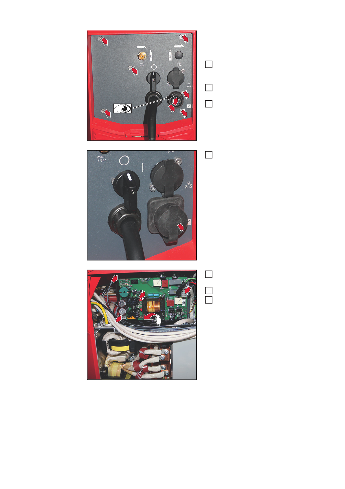
Remove cover
21

IMPORTANT! When inserting the socket,
16
17
17
16
17
18
18
X1
19
20
19
20
21
make sure that the word "Top" / the wide recess is at the top.
Insert the socket of the cable harness
with socket into the opening, pushing
from the inside to the outside
Secure the socket with two TX20
screws
Attach the cover over the socket
Connect gray cable to X1 on PC board
BRTSFMAG50
Secure cable with cable tie and mount
for cable tie, cut cable tie to length
Fit right side panel of the power source
22

Installing the OPT/i TPS C Ext. Welding Release in
3
6 x TX25
1
2
4
5
6
7
3
2 x TX25
1
2
3
5
1
1
1
1
TPS 270i C
Preparation Switch off the power source and disconnect from the grid
1
5 6
2
1
5 x TX25
5
7 8
4
EN-US
3
2
6
4
Installing the
OPT/i TPS C Ext.
Welding Release
1
Guide the cable harness with socket
near to the gas hose to the front of the
power source
23

IMPORTANT! When inserting the socket,
4
2
4
4
4
3
3
4
2
3
4
5
5
6
6
6
8
7
6
7
8
make sure that the word "Top" / the wide recess is at the top.
Insert the socket of the cable harness
with socket into the opening, pushing
from the inside to the outside
Secure the socket with two TX20 4 x 12
mm screws
Secure the rear with five TX25 screws
Attach the cover over the socket
Disconnect all cables and plugs from
PC board NT601
Remove the brass spacer size 8 mm
Remove PC board NT601 with holder
24

Position PC board BRTSFMAG50 on
11
9
10
10
9
10
11
14
14
12
13
12
14
15
12
13
14
15
16
16
the rear of the holder
Secure PC board BRTSFMAG50 with
two TX20 4 x 8 mm screws
Tightening torque = 1.5 Nm
Connect the 10-pin plug from the cable
harness to PC board BRTSFMAG50
Push in both PC boards with holder until they engage
Fit the brass spacer size 8 mm
Connect all cables and plugs to PC
board NT601
Disconnect the 6-pin plug from PC
board SMB2700
EN-US
Connect the cable coming from the
rear to PC board BRTSFMAG50
25

Connect the 6-pin plug to the Y-piece
17
17
18
17
18
19
19
20
20
20
Connect the other end of the Y-piece to
PC board SMB2700
Disconnect and dispose of the gray
plug
Connect the remaining plugs from the
cable harness
26

Guide the two gray single cables from
21
22
21
21
22
21
22
23
23
23
23
2
the cable harness to plug X14 and plug
them into X14/14 and X14/15 as per
the lettering on the cables
Connect the cable from the device ID
to X14:
green cable to X14/21
gray cable to X14/22
Secure cable using cable tie, cut cable
tie to length
EN-US
Final Tasks Use two TX25 screws to fit the control panel to the power source
1
Fit right side panel of the power source
27

Installing the OPT/i TPS C Ext. Welding Release in
1
1
1
TPS 320i C
Installing the
OPT/i TPS C Ext.
Welding Release
in TPS 320i C
The OPT/i TPS C Ext. Weld. Release is installed in the TPS 320i C in the same way as in
the TPS 270i C.
The only difference is that the cable from the cable harness with socket is guided through
the cable tunnel provided to the front of the power source:
Guide the cable harness with socket
through the cable tunnel to the front
24
28

Pin Assignment
Pin assignments
Pin Assignment Colour
1
2
3 STOP brown
4 STOP-GND pink
5
6 DISABLED grey
7 +24 V yellow
8
max. cabel length 30 m
EN-US
29

30

EN-US
31

FRONIUS INTERNATIONAL GMBH
Froniusstraße 1, A-4643 Pettenbach, Austria
E-Mail: sales@fronius.com
www.fronius.com
Under www.fronius.com/contact you will find the addresses
of all Fronius Sales & Service Partners and locations
 Loading...