


/ Perfect Charging / Perfect Welding / Solar Energy
OPT/i TPS Doppelkopf Robotics
OPT/i TPS double-head Robotics
Installationsanleitung
DEEN
MIG/MAG-Stromquelle
Installations instructions
MIG/MAG Power source
42,0410,2338 001-31072017

2

Allgemeines
DE
Sicherheit
WARNUNG! Ein elektrischer Schlag kann tödlich sein. Vor Öffnen des Gerätes
- Netzschalter in Stellung - O - schalten
- Gerät vom Netz trennen
- ein verständliches Warnschild gegen Wiedereinschalten anbringen
- mit Hilfe eines geeigneten Messgerätes sicherstellen, dass elektrisch geladene Bauteile (z.B. Kondensatoren) entladen sind
WARNUNG! Fehlerhaft durchgeführte Arbeiten können schwerwiegende Personen- und Sachschäden verursachen. Nachfolgend beschriebene Tätigkeiten dürfen nur von geschultem Fachpersonal durchgeführt werden! Beachten Sie das
Kapitel „Sicherheitsvorschriften“ in der Bedienungsanleitung der Stromquelle und
der Systemkomponenten.
Voraussetzung Für den Betrieb des Einbau-Sets OPT/i TPS 4x Switch SpeedNet darf das Einbau-Set
OPT/i TPS 2. SpeedNet Connector (4,100,812) nicht an der Stromquelle vorhanden sein.
Bei vorhandenem Roboter-Interface muss die schwarze SpeedNet-Leitung des RoboterInterfaces vom Print SMB5000 abgesteckt und am Print SCRATSW angesteckt werden.
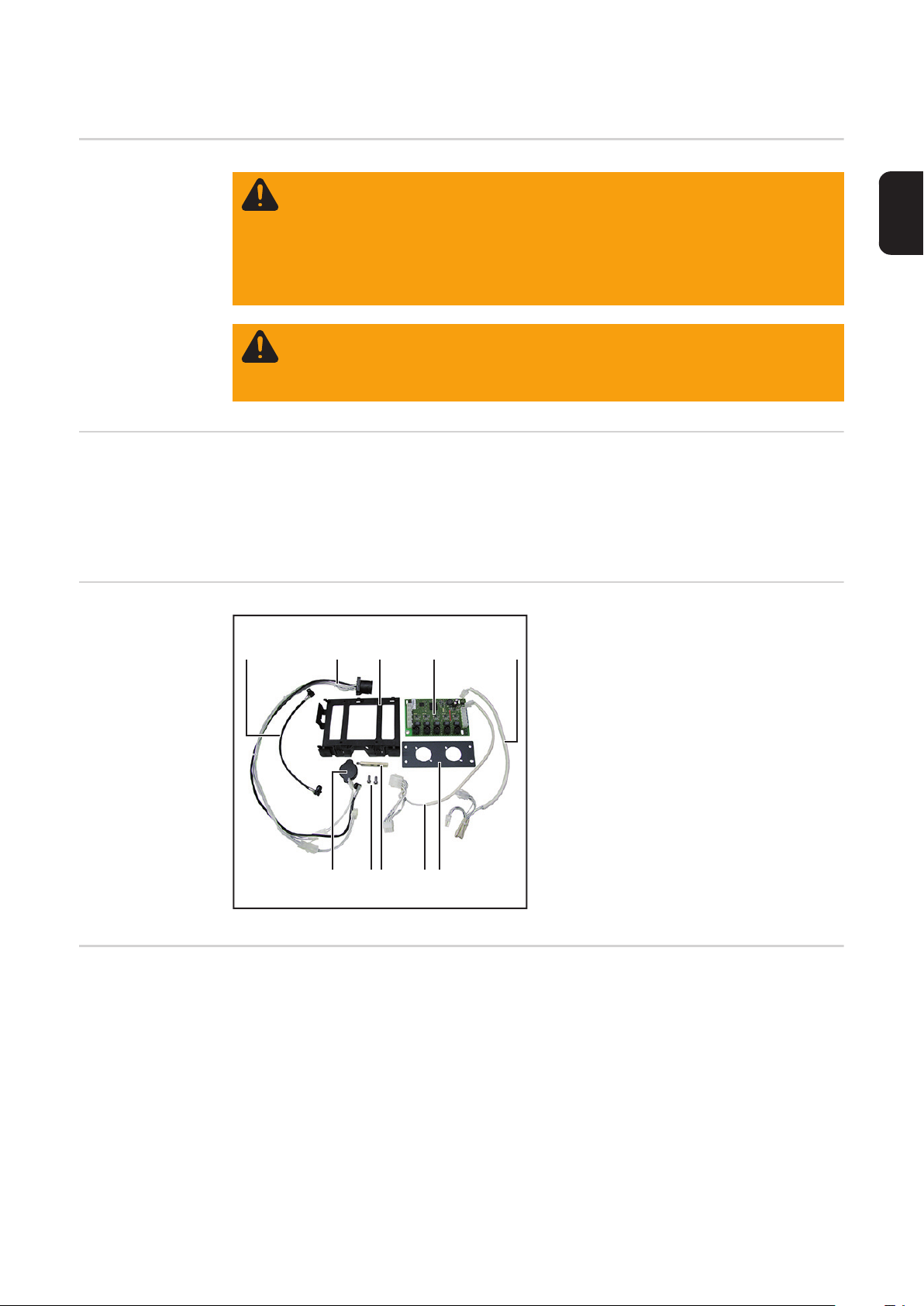
Lieferumfang
(1) (2) (3) (4) (5)
(1) 1 x Kabel schwarz
(2) 2 x Kabelbaum schwarz / weiß
(3) 1 x Print-Halterung
4p
2p
(4) 1 x Print SCRATSW
(5) 1 x Kabelbaum 4p / 4p
(6) 1 x Montageplatte
(7) 1 x Kabelbaum 2p / 8p
(8) 1 x Messingdistanz
(9) 4 x Schraube TX25
(10) 1 x Blindabdeckung
8p
8p
4p
4p
ohne Abbildung:
(9)(10)
(6)(7)(8)
1 x Installationsanleitung
Erforderliche
Werkzeuge
- Torx Schraubendreher TX 25
- Steckschlüssel SW 8 mm
- Seitenschneider
3

OPT/i TPS Doppelkopf Robotics an der Geräte-Rückseite einbauen
Vorbereitung Stromquelle ausschalten und vom Netz trennen
1
Rechten Seitenteil der Stromquelle entfernen
2
1
3
1
Print gemäß Abbildung in die Halterung einsetzen
2
4
Print nach rechts verschieben und in der Halterung fixieren
3
5
4
6
1
1
5
Platte an der Rückseite entfernen
1
2
2
3
1
4
3
5
4
Montageplatte montieren, Anzugsmoment = 3 Nm
4

1
7
DE
B
2
OPT/i TPS Doppelkopf Robotics
an der Rückseite
einbauen
A
Blindabdeckung von Position A entfernen und auf
Position B einsetzen
1
SMB5000
1
(1)
Kabel schwarz (1) am freien Stecker
1
am Print SMB 5000 anstecken
WICHTIG! Wenn kein freier Stecker am
Print SMB5000 vorhanden ist (z.B. bei vorhandenem Roboter-Interface):
- Kabel zum Roboter-Interface vom Print
SMB5000 abstecken
- Kabel zum Roboter-Interface anschließend am Print SCRATSW anstecken
(3)
(2)
NT241
3
3
Der Print NT241 liegt unter dem Print
NT601.
8-poliges Kabel (2) vom Print NT241
2
abstecken
4
NT601
Kabelbaum 2p / 8p (3) aus dem Liefer-
3
umfang des Einbau-Sets mit dem 8poligen Kabel (2) zusammenstecken
Kabelbaum 2p / 8p (3) am Print NT241
4
anstecken
5
4-poliges Kabel (4) vom Print NT601
5
abstecken
(4)
5

(4)
NT601
Kabelbaum 4p / 4p (5) am Print NT601
6
anstecken
Kabelbaum 4p / 4p (5) mit dem 4-poli-
7
gen Kabel (4) zusammenstecken
6
7
7
(5)
Kabel schwarz (1) durch die Print-Hal-
8
terung führen
Print (6) mit Print-Halterung bis zum 2.
9
X10
Mal Einrasten einschieben
SCRATSW
9
(6) (1)
12
SCRATSW
13
10
9
X11
X12
X13
X14
11
8
(1) (5)
X10
Messingdistanz (7) einschrauben
10
Anzugsmoment = 1,8 Nm
Kabel schwarz (1) am Print SCRATSW
11
/ X10 anstecken
Kabelbaum 2p / 8p (3) am Print
12
SCRATSW anstecken
Kabelbaum 4p / 4p (5) am Print
13
SCRATSW anstecken
(3)(7)
6

16
15
16
14
(8)
WICHTIG! Beim Einsetzen der SpeedNetAnschlüsse darauf achten, dass die Markierung „TOP“ oben ist.
Anschlüsse SpeedNet vom Kabel-
14
baum schwarz / weiß (8) an der Rückseite der Stromquelle von innen nach
außen in die freien Öffnungen einsetzen
Anschlüsse SpeedNet mit jeweils 2
15
Schrauben aus dem Lieferumfang des
Einbau-Sets befestigen
Anzugsmoment = 1,8 Nm
Aufkleber 1, 2, und 3 gemäß Abbildung
16
anbringen
DE
15
15
17
16
15
17
Abdeckkappen anbringen
17
7

19
(8)
Schwarzes Kabel vom Kabelbaum
(11)
20
21
X10
21
18
X11
(9)
21
X12
X13
X14
18
schwarz / weiß (8) am Print SCRATSW
/ X12 anstecken
Weißes 4-poliges Kabel vom Kabel-
19
baum schwarz / weiß (8) am Print
SCRATSW anstecken
Weißes 2-poliges Kabel vom Kabel-
20
baum schwarz / weiß (8) am Print
SCRATSW anstecken
Die Arbeitsschritte 18 - 20 für die Posi-
21
tion (9), (10) und (11) wiederholen
==> X13
(10)
Abschließende
Tätigkeiten
Kabel mit Kabelbinder fixieren
1
Rechten Seitenteil der Stromquelle montieren
2
8
General
Safety
WARNING! An electric shock can be fatal. Before opening the device
- Turn the mains switch to the "O" position
- Unplug the machine from the mains
- Put up an easy-to-understand warning sign to stop anybody inadvertently
switching it back on again
- Using a suitable measuring instrument, check to make sure that electrically
charged components (e.g. capacitors) have discharged
WARNING! Work that is carried out incorrectly can cause serious injury and damage. The following activities must only be carried out by trained and qualified personnel. Read the "Safety rules" chapter in the power source and system
components operating instructions.
Prerequisite The OPT/i TPS 4x Switch SpeedNet installation set is not compatible with power sources
with the OPT/i TPS 2nd SpeedNet connector installation set (4,100,812) fitted.
If a robot interface is present, the black SpeedNet line of the robot interface must be disconnected from the SMB5000 PC board and connected to the SCRATSW PC board.
Scope of supply
(1) (2) (3) (4) (5)
(1) 1x black cable
(2) 2x black/white cable harness
(3) 1x PC board holder
4p
2p
(4) 1x SCRATSW PC board
(5) 1x 4p/4p cable harness
(6) 1x mounting plate
(7) 1x 2p/8p cable harness
(8) 1x brass spacer
(9) 4x TX25 screws
(10) 1x blanking cover
8p
8p
4p
4p
Not shown:
(9)(10)
(6)(7)(8)
1x Installation Instructions
EN
Tools required - TX25 Torx screwdriver
- 8 mm socket wrench
- Diagonal cutting pliers
9

Installing the OPT/i TPS double-head Robotics on
the rear of the device
Preparatory work Switch off the power source and disconnect it from the mains
1
Remove the right side panel from the power source
2
2
3
1
Fit the PC board into the holder as illustrated
4
5
3
4
Slide the PC board to the right and secure in the holder
5
6
1
1
Remove the plate on the rear
1
2
2
5
1
4
3
3
5
4
Fit the mounting plate, tightening torque = 3 Nm
10

1
7
EN
B
2
Installing the
OPT/i TPS double-head Robotics on the rear of
the device
A
Remove the blanking cover from position A and insert at position B
1
SMB5000
1
(1)
Connect the black cable (1) to the free
1
connector on the SMB5000 PC board
IMPORTANT! If there is no free connector
available on the SMB5000 PC board (e.g.
with robot interface present):
- Disconnect the robot interface cable
from the SMB5000 PC board
- Connect the robot interface cable to
the SCRATSW PC board
(3)
(2)
NT241
3
3
The NT241 PC board is underneath the
NT601 PC board.
Detach the 8-pin cable (2) from the
2
NT241 PC board
4
NT601
Connect the 2p/8p cable harness (3)
3
from the installation set to the 8-pin cable (2)
Connect the 2p/8p cable harness (3) to
4
the NT241 PC board
5
Detach the 4-pin cable (4) from the
5
NT601 PC board
(4)
11

(4)
SCRATSW
NT601
Connect the 4p/4p cable harness (5) to
6
the NT601 PC board
Connect the 4p/4p cable harness (5) to
7
the 4-pin cable (4)
6
7
7
(5)
Guide the black cable (1) through the
8
PC board holder
Push in the PC board (6) with PC board
9
X10
holder until it engages for the second
time
X11
X12
X13
8
X14
9
9
(6) (1)
12
SCRATSW
13
10
11
(1) (5)
X10
(3)(7)
Screw in the brass spacer (7)
10
Tightening torque = 1.8 Nm
Connect the black cable (1) to the
11
SCRATSW PC board / X10
Connect the 2p/8p cable harness (3) to
12
the SCRATSW PC board
Connect the 4p/4p cable harness (5) to
13
the SCRATSW PC board
12

16
15
16
14
(8)
IMPORTANT! When inserting the SpeedNet connection sockets, ensure that the
side marked "TOP" is at the top.
Starting from the inside, push the
14
SpeedNet connection sockets of the
black/white cable harness (8) through
the free openings on the rear of the power source
Secure the SpeedNet connection so-
15
ckets using two screws from the installation set on each socket
Tightening torque = 1.8 Nm
Affix stickers 1, 2 and 3 as shown
16
EN
15
15
17
16
15
17
Fit cover caps
17
13
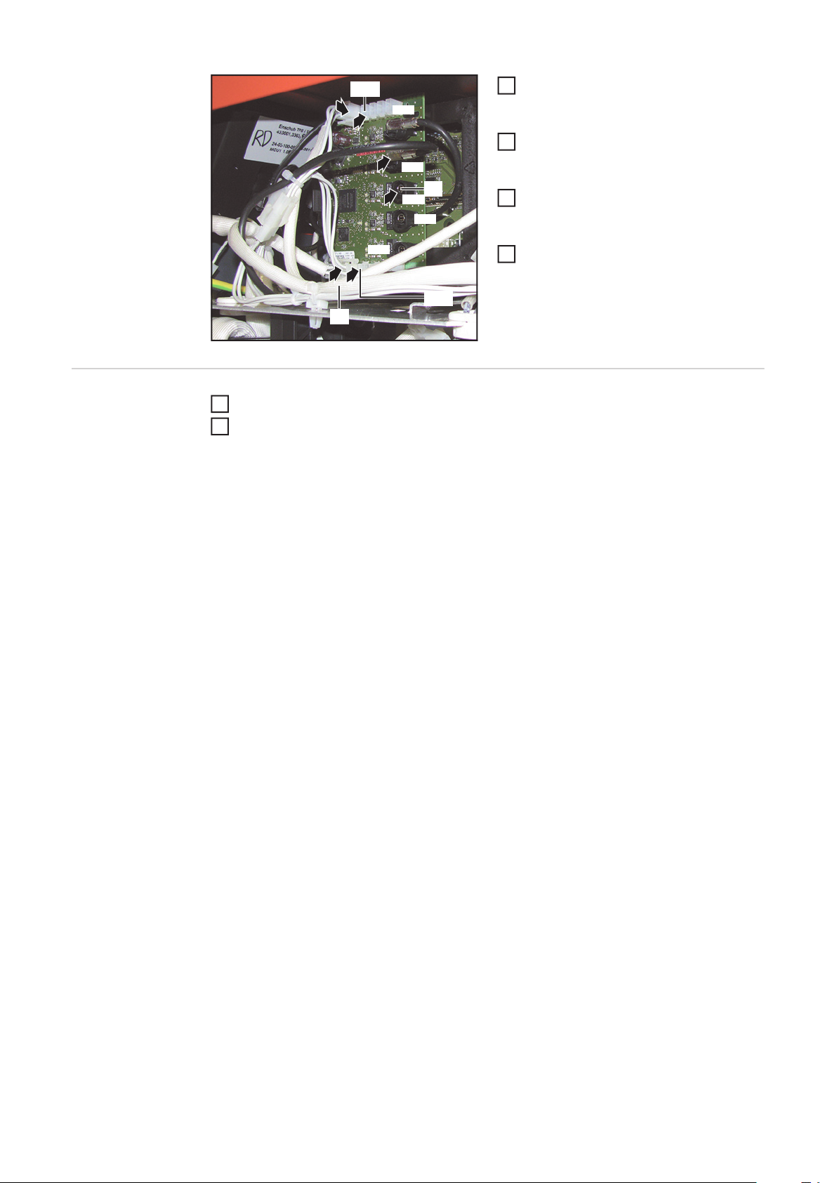
19
(8)
Connect the black cable from the
(11)
20
21
X10
21
18
X11
(9)
21
X12
X13
X14
18
black/white cable harness (8) to the
SCRATSW PC board / X12
Connect the white 4-pin cable from the
19
black/white cable harness (8) to the
SCRATSW PC board
Connect the white 2-pin cable from the
20
black/white cable harness (8) to the
SCRATSW PC board
Repeat steps 18 - 20 for positions (9),
21
(10) and (11)
==> X13
(10)
And finally... Bind cables together with cable ties
1
Attach the right side panel to the power source
2
14

EN
15

FRONIUS INTERNATIONAL GMBH
Froniusplatz 1, A-4600 Wels, Austria
Tel: +43 (0)7242 241-0, Fax: +43 (0)7242 241-3940
E-Mail: sales@fronius.com
www.fronius.com
www.fronius.com/addresses
Under http://www.fronius.com/addresses you will find all addresses
of our Sales & service partners and Locations
 Loading...