

Page 1

Fronius prints on elemental chlorine free paper (ECF) sourced from certified sustainable forests (FSC).
/ Perfect Charging / Perfect Welding / Solar Energy
OPT/i TPS C Ethernet
Installationsanleitung
DEENFR
MIG/MAG-Stromquelle
Installations instructions
MIG/MAG Power source
Instructions d'installation
Source de courant MIG/MAG
42,0410,2223 002-12062019
Page 2

2
Page 3

Allgemeines
DE
Sicherheit
Lieferumfang
WARNUNG!
Ein elektrischer Schlag kann tödlich sein.
Vor Öffnen des Gerätes
► Netzschalter in Stellung - O - schalten
► Gerät vom Netz trennen
► ein verständliches Warnschild gegen Wiedereinschalten anbringen
► mit Hilfe eines geeigneten Messgerätes sicherstellen, dass elektrisch geladene Bau-
teile (z.B. Kondensatoren) entladen sind
WARNUNG!
Fehlerhaft durchgeführte Arbeiten können schwerwiegende Personen- und Sachschäden verursachen.
► Nachfolgend beschriebene Tätigkeiten dürfen nur von geschultem Fachpersonal
durchgeführt werden!
► Beachten Sie das Kapitel „Sicherheitsvorschriften“ in der Bedienungsanleitung der
Stromquelle und der Systemkomponenten.
(1) 2 Schrauben TX20
(2) Abdeckung
(3) Ethernet-Kabel mit Buchse
Erforderliche
Werkzeuge
- Torx Schraubendreher TX 20
- Torx Schraubendreher TX 25
(1)
(2)
(3)
ohne Abbildung:
diese Einbauanleitung
3
Page 4

OPT/i TPS C Ethernet in TPS 270i C einbauen
Vorbereitung
1 2
1
4
3 4
5
7
2
3
6
1
6 x TX25
3
1 x TX25
2
1
5
4
2 x TX25
3
2
6
5 x TX25
4
1
5 6
5
3 x TX25
1
5
2x
6
3
2
4
3
1
2
6
1
2
1
4
Page 5

7 8
7
6
1
2
3
7
4
5
5 x TX25
8
DE
1
OPT/i TPS C
Ethernet in
TPS 270i C einbauen
Abdeckung von innen nach außen in
2 x TX20
2,1 Nm
2
1
1
2
1
die Öffnung an der Rückseite einsetzen
Abdeckung mit 2 Schrauben TX20 aus
2
dem Lieferumfang fixieren
Anzugsmoment = 2,1 Nm
Ethernet-Kabel im Kabelkanal verle-
3
gen:
Ethernet-Buchse zur Rückseite
Stecker zur Vorderseite
3
3
3
3
5
Page 6

WICHTIG! Beim Einsetzen der EthernetBuchse darauf achten, dass die Feder an
der Ethernet-Buchse unten ist!
Ethernet-Buchse von innen nach au-
4
ßen in die Abdeckung einsetzen und
4
einrasten lassen
Stecker des Ethernet-Kabels am freien
5
Stecker am Print anstecken
5
5 x TX25
3 Nm
WICHTIG! Beim Einsetzen der Abdeckungen darauf achten, dass
- bei der oberen Abdeckung die Blechla-
6
7
7
7
6
7
7
sche innen ist,
- Kabel nicht geknickt, eingeklemmt, abgeschert oder sonst irgendwie beschädigt werden.
Abdeckungen einsetzen
6
Abdeckungen mit 5 Schrauben TX25
7
fixieren
Anzugsmoment = 3 Nm
6
Page 7

Abschließende
Tätigkeiten
WICHTIG! Beim Montieren des Gerätedeckels darauf achten, dass Kabel und Schläuche
nicht geknickt, eingeklemmt, abgeschert oder sonst irgendwie beschädigt werden.
Zusammenbau in umgekehrter Reihenfolge wie bei der Vorbereitung:
Gerätedeckel und Tragegriff montieren
1
Bedienpanel montieren
2
Anzugsmoment der 2 TX25 Schrauben = 1,5 Nm
Kunststoff-Abdeckung montieren
3
Runde Kunststoff-Klipse am Tragegriff anbringen (2x)
4
An der Geräte-Rückseite die mittlere Schraube TX25 (= Verschraubung Deckel) ein-
5
setzen und festziehen
An der Geräte-Rückseite das Anschlussblech montieren
6
Rechten Seitenteil montieren
7
Anzugsmoment für alle übrigen TX25-Schrauben = 3 Nm
DE
7
Page 8

OPT/i TPS C Ethernet in TPS 320i C einbauen
Vorbereitung Stromquelle ausschalten und vom Netz trennen
1
9 10
2
2
1
5
3
4
5
11 12
4
TX25
4
3
5
5
7
3
6
1
1
4
2
TX25
3
1
TX25
2
13 14
6
TX25
1
1
2
3
1
TX25
3
4
1
2x
5
2
7
1
3
2
8
Page 9

15
8
DE
1
OPT/i TPS C
Ethernet in
TPS 320i C einbauen
Buchsengehäuse gemäß Abbildung
1
von innen nach außen in die Öffnung
an der Rückseite einsetzen
1
Buchsengehäuse mit 2 Schrauben
2
TX20 an der Rückseite fixieren
Anzugsmoment = 2,1 Nm
Abdeckung über dem Buchsengehäu-
2
3
3
se anbringen
2
9
Page 10

WICHTIG! Beim Einsetzen der EthernetBuchse darauf achten, dass die Feder an
der Ethernet-Buchse unten ist.
Ethernet-Buchse gemäß Abbildung
4
von innen nach außen in das Buchsengehäuse einsetzen und einrasten las-
4
sen
Schutzschlauch über der Ethernet-
5
Buchse anbringen
Kabel von der Ethernet-Buchse im
6
vorhandenen Kabelkanal nach vorne
zum Bedienpanel verlegen
6
7
6
6
6
Kabel am Bedienpanel anstecken
7
10
Page 11

Abschließende
Tätigkeiten
WICHTIG! Beim Montieren des Gerätedeckels darauf achten, dass Kabel und Schläuche
nicht geknickt, eingeklemmt, abgeschert oder sonst irgendwie beschädigt werden.
Zusammenbau in umgekehrter Reihenfolge wie bei der Vorbereitung:
Gerätedeckel und Tragegriff montieren
1
Deckel an der Geräte-Vorderseite mit 3 TX25 Schrauben am Gehäuse fixieren
2
Anzugsmoment = 3 Nm
Bedienpanel montieren
3
Anzugsmoment der 2 TX25 Schrauben = 3 Nm
Kunststoff-Abdeckung montieren
4
Runde Kunststoff-Klipse am Tragegriff anbringen (2x)
5
An der Geräte-Rückseite das Anschlussblech montieren
6
Rechten Seitenteil montieren
7
Anzugsmoment für alle übrigen TX25-Schrauben = 3 Nm
DE
11
Page 12

12
Page 13

General
Safety
Scope of supply
WARNING!
An electric shock can be fatal.
Before opening the device
► Turn the mains switch to the "O" position
► Unplug the device from the mains
► Put up an easy-to-understand warning sign to stop anybody inadvertently switching it
back on again
► Using a suitable measuring instrument, check to make sure that electrically charged
components (e.g. capacitors) have been discharged
WARNING!
Work that is carried out incorrectly can cause serious injury or damage.
► The following activities may only be carried out by trained and qualified personnel.
► Read the "Safety rules" chapter in the power source and system components Operat-
ing Instructions.
(1) Two TX20 screws
(2) Cover
(3) Ethernet cable with socket
EN
Tools required - Torx screwdriver TX 20
- Torx screwdriver TX25
(1)
(2)
(3)
Not shown:
these installation instructions
13
Page 14
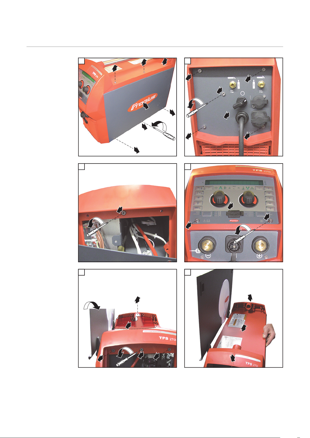
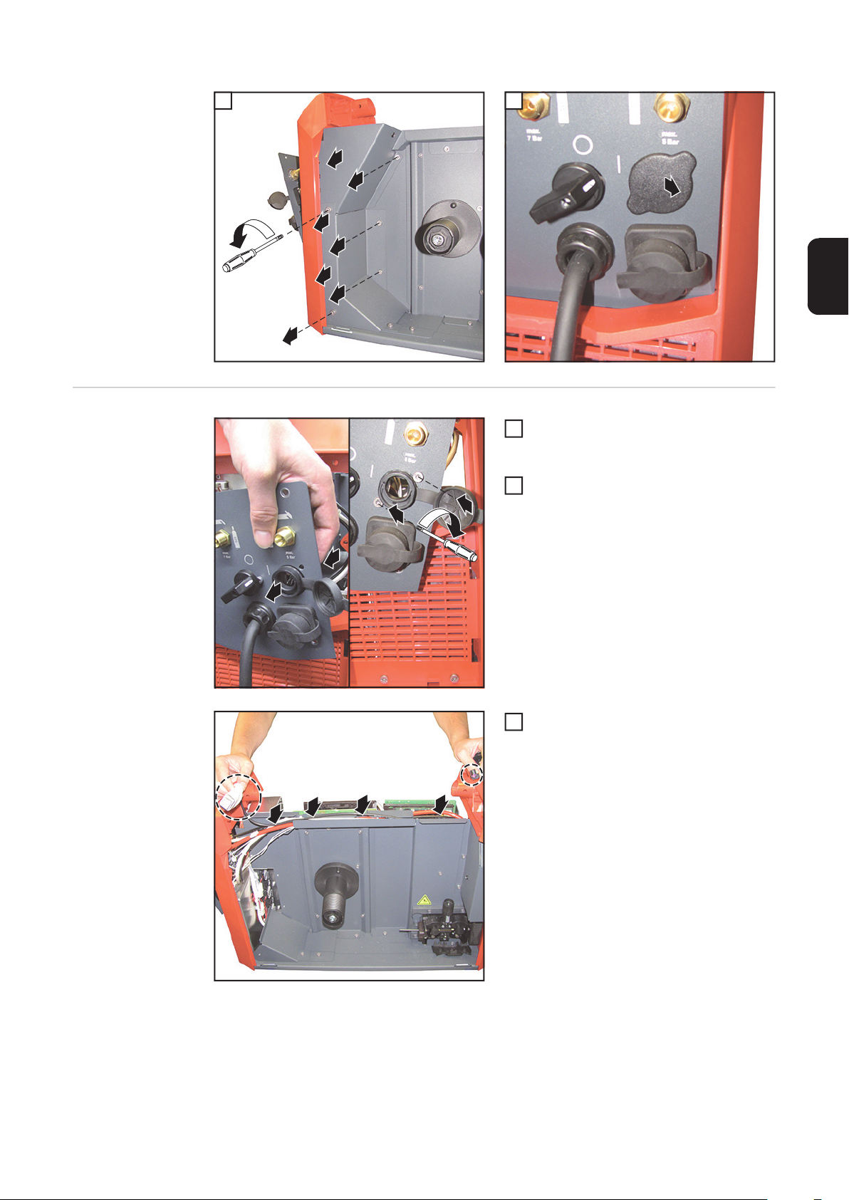
Installing the OPT/i TPS C Ethernet in the TPS 270i C
Preparations
1 2
1
4
3 4
5
7
2
3
6
1
6 x TX25
3
1 x TX25
2
1
5
4
2 x TX25
3
2
6
5 x TX25
4
1
5 6
5
3 x TX25
1
5
2x
6
3
2
4
3
1
2
6
1
2
1
14
Page 15

7 8
7
6
1
2
3
7
4
5
5 x TX25
8
1
EN
Installing the
OPT/i TPS C
Ethernet in the
TPS 270i C
Insert the cover into the opening on the
2 x TX20
2,1 Nm
1
rear from the inside
Secure the cover using the two TX20
2
screws supplied
2
1
1
2
Tightening torque = 2.1 Nm
Route the Ethernet cable in the cable
3
duct:
Ethernet socket to the rear
Connector to the front
3
3
3
3
15
Page 16

IMPORTANT! When inserting the Ethernet
socket, ensure that the spring on the Ethernet socket is at the bottom.
Insert the Ethernet socket into the co-
4
ver from the inside and make sure it
4
engages in place
Insert the Ethernet cable plug into the
5
available connector on the PC board
5
5 x TX25
3 Nm
IMPORTANT! When inserting the covers,
ensure that
- the tab is on the inside for the upper co-
6
7
7
7
6
7
7
ver
- the cables are not kinked, trapped,
sheared or damaged in any way.
Fit the covers
6
Secure the covers with five TX25
7
screws
Tightening torque = 3 Nm
16
Page 17

And finally... IMPORTANT! When fitting the device cover, ensure that the cables and hoses are not
kinked, trapped, sheared or damaged in any way.
Assemble in the reverse sequence to the preparatory work:
Fit the device lid and carrying handle
1
Fit the control panel
2
Tightening torque for the two TX25 screws = 1.5 Nm
Fit the plastic cover
3
Attach the round plastic clips to the carrying handle (2x)
4
Insert and tighten the central TX25 screw (= cover screw) on the rear of the device
5
Fit the connection plate to the rear of the device
6
Fit the right side panel
7
Tightening torque for all remaining TX25 screws = 3 Nm
EN
17
Page 18

Installing the OPT/i TPS C Ethernet in the TPS 320i C
Preparation Switch off the power source and disconnect it from the mains
1
9 10
2
2
1
5
3
4
5
11 12
4
TX25
4
3
5
1
5
1
TX25
4
7
3
6
2
3
1
TX25
2
13 14
6
TX25
1
1
2
3
1
TX25
3
4
1
2x
5
2
7
1
3
2
18
Page 19

15
8
EN
1
Installing the
OPT/i TPS C
Ethernet in the
TPS 320i C
Insert the socket housing into the
1
opening on the rear from the inside as
shown
1
Secure the socket housing to the rear
2
panel with two TX20 screws
Tightening torque = 2.1 Nm
Fit the cover over the socket housing
2
3
3
2
19
Page 20

IMPORTANT! When inserting the Ethernet
socket, ensure that the spring on the Ethernet socket is at the bottom.
Insert the Ethernet socket into the so-
4
cket housing from the inside as shown
and make sure it engages in place
4
Fit the protective hose over the Ether-
5
net socket
Route the cable forwards from the
6
Ethernet socket to the control panel in
the existing cable duct
6
7
6
6
6
Connect the cable to the control panel
7
20
Page 21

And finally... IMPORTANT! When fitting the device cover, ensure that the cables and hoses are not
kinked, trapped, sheared or damaged in any way.
Assemble in the reverse sequence to the preparatory work:
Fit the device lid and carrying handle
1
Secure the lid to the housing on the front of the device using three TX25 screws
2
Tightening torque = 3 Nm
Fit the control panel
3
Tightening torque for the two TX25 screws = 3 Nm
Fit the plastic cover
4
Attach the round plastic clips to the carrying handle (2x)
5
Fit the connection plate to the rear of the device
6
Fit the right side panel
7
Tightening torque for all remaining TX25 screws = 3 Nm
EN
21
Page 22

22
Page 23

Généralités
Sécurité
AVERTISSEMENT !
Une décharge électrique peut être mortelle.
Avant d'ouvrir l'appareil :
► placer l'interrupteur secteur en position - O - ;
► débrancher l'appareil du réseau ;
► apposer un panneau d'avertissement compréhensible afin de prévenir toute remise en
marche ;
► s'assurer, à l'aide d'un appareil de mesure approprié, que les composants à charge
électrique (par ex. : condensateurs) sont déchargés.
AVERTISSEMENT !
Des travaux mal effectués peuvent entraîner des dommages corporels et matériels
graves.
► Les opérations décrites ci-après doivent être effectuées exclusivement par du person-
nel qualifié et formé !
► Respecter les prescriptions du chapitre « Consignes de sécurité » figurant dans les
instructions de service de la source de courant et des composants périphériques.
FR
Contenu de la livraison
Outils nécessaires
- Tournevis Torx TX 20
- Tournevis Torx TX 25
(1)
(2)
(3)
(1) 2 vis TX20
(2) Cache
(3) Câble Ethernet avec connecteur
sans illustration :
les présentes Instructions d'installation
23
Page 24

Installer le câble Ethernet OPT/i TPS C sur le TPS
270i C
Préparation
1 2
1
4
3 4
5
7
2
3
6
1
6 x TX25
3
1 x TX25
2
1
5
4
2 x TX25
3
2
6
5 x TX25
4
1
5 6
5
3 x TX25
1
5
2x
6
3
2
4
3
1
2
6
1
2
1
24
Page 25
7 8
7
6
1
2
3
5 x TX25
8
1
Installer le câble
Ethernet OPT/i
TPS C sur le
TPS 270i C
7
4
5
Placer le cache depuis l'intérieur vers
2 x TX20
2,1 Nm
2
1
1
2
1
l'extérieur dans l'ouverture sur la face
arrière
Fixer le cache avec les 2 vis TX20
2
fournies
Couple de serrage = 2,1 Nm
FR
Placer le câble Ethernet dans le passa-
3
ge de câble :
le connecteur Ethernet vers la face arrière
la prise vers la face avant
3
3
3
3
25
Page 26

IMPORTANT ! Lors de la mise en place du
connecteur Ethernet, veiller à ce que le ressort sur le connecteur soit situé en bas !
Placer le connecteur Ethernet depuis
4
l'intérieur vers l'extérieur dans le cache
4
et l'enclencher
Brancher la prise du câble Ethernet au
5
connecteur libre du circuit imprimé
5
5 x TX25
3 Nm
IMPORTANT ! Lors de la mise en place du
cache, veiller à ce que :
- la languette de tôle du cache supérieur
6
7
7
7
6
7
7
se trouve à l'intérieur,
- le câble ne soit pas coincé, coudé, cisaillé, ou endommagé de toute autre
manière.
Mettre les caches en place
6
Fixer les caches avec 5 vis TX25
7
Couple de serrage = 3 Nm
26
Page 27

Étapes finales IMPORTANT ! Lors du montage du couvercle de l'appareil, veiller à ce que le câble et les
tuyaux ne soient pas coincés, coudés, cisaillés ou endommagés de toute autre manière.
Montage dans l'ordre inverse comme lors de la préparation :
Monter le couvercle de l'appareil et la poignée de transport
1
Monter le panneau de commande
2
Couple de serrage des 2 vis TX25 = 1,5 Nm
Monter le cache en plastique
3
Placer les clips en plastique ronds sur la poignée de transport (2x)
4
Placer et serrer la vis centrale TX25 (= couvercle vissé) sur la face arrière de l'appareil
5
Monter la tôle de raccordement sur la face arrière de l'appareil
6
Monter la partie latérale droite
7
Couple de serrage pour toutes les autres vis TX25 = 3 Nm
FR
27
Page 28

Installer le câble Ethernet OPT/i TPS C sur le TPS
320i C
Préparation Désactiver la source de courant et la débrancher du secteur
1
9 10
2
2
1
5
3
4
5
11 12
4
TX25
4
3
1
5
5
1
TX25
4
7
3
6
2
3
1
TX25
2
13 14
6
TX25
1
1
2
3
1
TX25
3
4
1
2x
5
2
7
1
3
2
28
Page 29

15
8
FR
1
Installer le câble
Ethernet OPT/i
TPS C sur le
TPS 320i C
Placer le boîtier douilles depuis l'intéri-
1
eur vers l'extérieur dans l'ouverture sur
la face arrière, conformément à l'illustration
1
Fixer le boîtier douilles à l'aide des
2
2 vis TX20 sur la face arrière
Couple de serrage = 2,1 Nm
Placer le cache sur le boîtier douilles
2
3
3
2
29
Page 30

IMPORTANT ! Lors de la mise en place du
connecteur Ethernet, veiller à ce que le ressort sur le connecteur soit situé en bas.
Placer le connecteur Ethernet, con-
4
formément à l'illustration, depuis l'intérieur vers l'extérieur dans le boîtier
4
douilles et l'enclencher
Placer la gaine de protection au-des-
5
sus du connecteur Ethernet
Faire avancer le connecteur Ethernet
6
dans le passage de câble fourni vers le
panneau de commande
6
6
6
6
Raccorder le câble au panneau de
7
commande
7
30
Page 31

Étapes finales IMPORTANT ! Lors du montage du couvercle de l'appareil, veiller à ce que le câble et les
tuyaux ne soient pas coincés, coudés, cisaillés ou endommagés de toute autre manière.
Montage dans l'ordre inverse comme lors de la préparation :
Monter le couvercle de l'appareil et la poignée de transport
1
Fixer le couvercle sur la face avant de l'appareil à l'aide de 3 vis TX25
2
Couple de serrage = 3 Nm
Monter le panneau de commande
3
Couple de serrage des 2 vis TX25 = 3 Nm
Monter le cache en plastique
4
Placer les clips en plastique ronds sur la poignée de transport (2x)
5
Monter la tôle de raccordement sur la face arrière de l'appareil
6
Monter la partie latérale droite
7
Couple de serrage pour toutes les autres vis TX25 = 3 Nm
FR
31
Page 32

FRONIUS INTERNATIONAL GMBH
Vorchdorfer Straße 40, A-4643 Pettenbach, Austria
E-Mail: sales@fronius.com
www.fronius.com
Under www.fronius.com/contact you will find the addresses
of all Fronius Sales & Service Partners and locations
 Loading...