

Page 1

Installation
instructions
OPT/i TPS 4x Switch SpeedNet
Installationsanleitung
DE
Installation instructions
EN
Instructions d'installation
FR
42,0410,2107 005-28032022
Page 2

Page 3

Allgemeines
(1) (2) (3) (4) (5)
(6)(7)(8)
(9)(10)
4p
4p
8p
2p
8p
4p
DE
Sicherheit
WARNUNG!
Gefahr durch Fehlbedienung und fehlerhaft durchgeführte Arbeiten.
Schwere Personen- und Sachschäden können die Folge sein.
Alle in diesem Dokument beschriebenen Arbeiten und Funktionen dürfen
▶
nur von technisch geschultem Fachpersonal ausgeführt werden.
Dieses Dokument vollständig lesen und verstehen.
▶
Sämtliche Sicherheitsvorschriften und Benutzerdokumentationen dieses
▶
Gerätes und aller Systemkomponenten lesen und verstehen.
WARNUNG!
Gefahr durch elektrischen Strom.
Schwere Personen- und Sachschäden können die Folge sein.
Vor Beginn der Arbeiten alle beteiligten Geräte und Komponenten ausschal-
▶
ten und von Stromnetz trennen.
Alle beteiligten Geräte und Komponenten gegen Wiedereinschalten sichern.
▶
Nach dem Öffnen des Gerätes mit Hilfe eines geeigneten Messgerätes si-
▶
cherstellen, dass elektrisch geladene Bauteile (beispielsweise Kondensatoren) entladen sind.
Voraussetzung Für den Betrieb des Einbau-Sets OPT/i TPS 4x Switch SpeedNet darf das Ein-
bau-Set OPT/i TPS 2. SpeedNet Connector (4,100,812) nicht an der Stromquelle
vorhanden sein.
Bei vorhandenem Roboter-Interface muss die schwarze SpeedNet-Leitung des
Roboter-Interfaces vom Print SMB5000 abgesteckt und am Print SCRATSW angesteckt werden.
Lieferumfang
(1) 1 x Kabel schwarz
(2) 1 x Kabelbaum schwarz / weiß
(3) 1 x Print-Halterung
(4) 1 x Print SCRATSW
(5) 1 x Kabelbaum 4p / 4p
(6) 1 x Montageplatte
(7) 1 x Kabelbaum 2p / 8p
(8) 1 x Messingdistanz
(9) 2 x Schraube TX25
(10) 1 x Blindabdeckung
ohne Abbildung:
1 x Einbauanleitung
3
Page 4

Hinweis zur
PrintBestückung
Je nach Version ist der Print SCRATSW unterschiedlich bestückt:
Print SCRATSW mit 5 SpeedNet-Anschlüssen Print SCRATSW mit 4 SpeedNet-Anschlüssen
Für diese Installationsanleitung wurde der Print SCRATSW mit 5 SpeedNetAnschlüssen verwendet.
Erforderliche
Werkzeuge
Torx Schraubendreher TX 25
-
Steckschlüssel SW 8 mm
-
Seitenschneider
-
4
Page 5

OPT/i TPS 4x Switch SpeedNet an der Geräte-
1
1
1
1
2
5
4
3
2
3
1
6
4
Rückseite einbauen
Vorbereitung
Stromquelle ausschalten und vom Netz trennen
1
Rechten Seitenteil der Stromquelle entfernen
2
3
DE
4
Print gemäß Abbildung in die Halterung einsetzen
5
Platte an der Rückseite entfernen
Print nach rechts verschieben und in der Halterung fixieren
6
Montageplatte montieren, Anzugsmoment = 3
Nm
5
Page 6

A
B
C
3
1
2
7
(1)
SMB5000
1
NT241
NT601
(3)
(2)
(4)
5
3
3
4
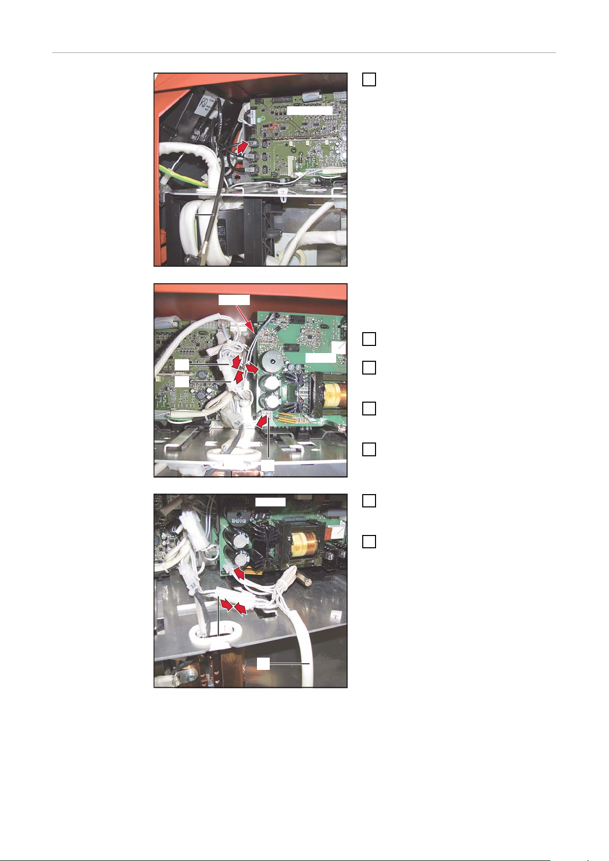
Blindabdeckung einsetzen
Der Speed Net-Anschluss kann an allen 3 Positionen A, B oder C montiert
werden. In die gewünschte Position
keine Blindabdeckung einsetzen.
OPT/i TPS 4x
Switch SpeedNet an der Rückseite einbauen
Kabel schwarz (1) am freien Ste-
1
cker am Print SMB 5000 anstecken
WICHTIG! Wenn kein freier Stecker
am Print SMB5000 vorhanden ist (z.B.
bei vorhandenem Roboter-Interface):
Kabel zum Roboter-Interface vom
-
Print SMB5000 abstecken
Kabel zum Roboter-Interface an-
-
schließend am Print SCRATSW
anstecken
Der Print NT241 liegt unter dem Print
NT601.
8-poliges Kabel (2) vom Print
2
NT241 abstecken
Kabelbaum 2p / 8p (3) aus dem
3
Lieferumfang des Einbau-Sets mit
dem 8-poligen Kabel (2) zusammenstecken
Kabelbaum 2p / 8p (3) am Print
4
NT241 anstecken
4-poliges Kabel (4) vom Print
5
NT601 abstecken
6
Page 7

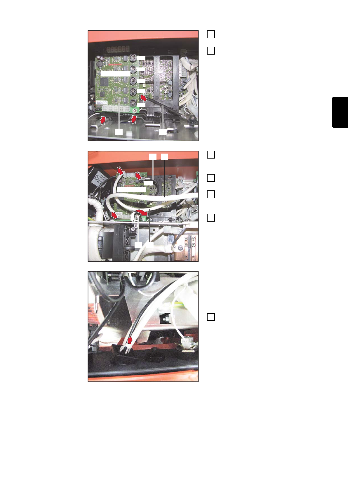
NT601
(5)
(4)
6
7
7
Kabelbaum 4p / 4p (5) am Print
SCRATSW
(6) (1)
X10
X11
X12
X13
X14
8
9
9
(1) (5)
SCRATSW
(3)(7)
X10
12
11
13
10
6
NT601 anstecken
Kabelbaum 4p / 4p (5) mit dem 4-
7
poligen Kabel (4) zusammenstecken
Kabel schwarz (1) durch die Print-
8
Halterung führen
Print (6) mit Print-Halterung bis
9
zum 2. Mal Einrasten einschieben
DE
Messingdistanz (7) einschrauben
10
Anzugsmoment = 1,8 Nm
Kabel schwarz (1) am Print
11
SCRATSW anstecken
Kabelbaum 2p / 8p (3) am Print
12
SCRATSW anstecken
Kabelbaum 4p / 4p (5) am Print
13
SCRATSW anstecken
7
Page 8

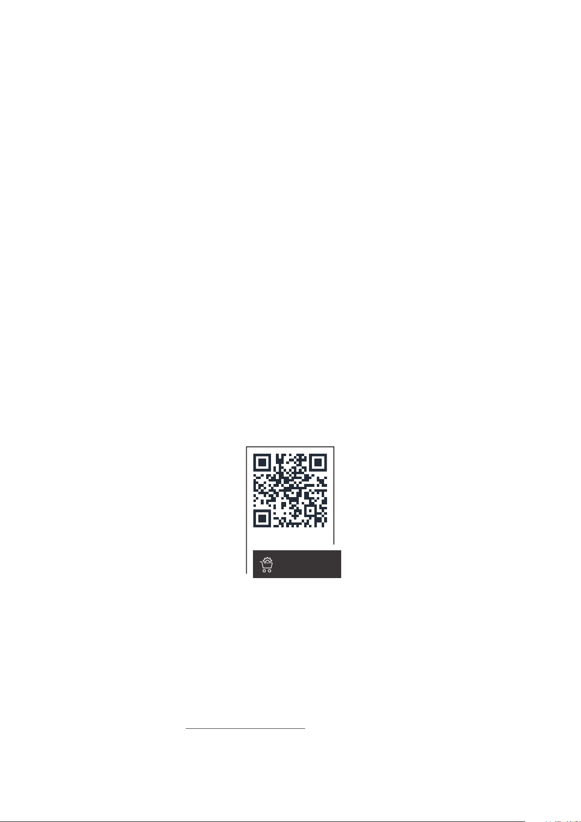
(8)
14
WICHTIG! Beim Einsetzen des Speed-
15
15
(8)
18
16
17
Net-Anschlusses darauf achten, dass
die Markierung „TOP“ oben ist.
Anschluss SpeedNet vom Kabel-
14
baum schwarz / weiß (8) an der
Rückseite der Stromquelle von innen nach außen in die freie Öffnung einsetzen
Anschluss SpeedNet mit den 2
15
Schrauben aus dem Lieferumfang
des Einbau-Sets befestigen
Anzugsmoment = 1,8 Nm
Abschließende
Tätigkeiten
16
17
18
Kabel mit Kabelbinder fixieren
1
Rechten Seitenteil der Stromquelle montieren
2
Schwarzes Kabel vom Kabelbaum
schwarz / weiß (8) am Print
SCRATSW anstecken
Weißes 4-poliges Kabel vom Kabelbaum schwarz / weiß (8) am Print
SCRATSW anstecken
Weißes 2-poliges Kabel vom Kabelbaum schwarz / weiß (8) am Print
SCRATSW anstecken
8
Page 9

OPT/i TPS 4x Switch SpeedNet an der Geräte-
1
1
1
1
4
2
3
Vorderseite einbauen
Vorbereitung
Stromquelle ausschalten und vom Netz trennen
1
Rechten Seitenteil der Stromquelle entfernen
2
3
DE
4
Print gemäß Abbildung in die Halterung einsetzen
5
2 Schrauben TX 25 entfernen
Bedienpanel heraus klappen
Blindabdeckung von innen nach außen entfernen
Print nach rechts verschieben und in der Halterung fixieren
9
Page 10

OPT/i TPS 4x
(1)
SMB5000
1
NT241
NT601
(3)
(2)
(4)
5
3
3
4
NT601
(5)
(4)
6
7
7
Switch SpeedNet an der Vorderseite einbauen
Kabel schwarz (1) am freien Ste-
1
cker am Print SMB 5000 anstecken
WICHTIG! Wenn kein freier Stecker
am Print SMB5000 vorhanden ist (z.B.
bei vorhandenem Roboter-Interface):
Kabel zum Roboter-Interface vom
-
Print SMB5000 abstecken
Kabel zum Roboter-Interface an-
-
schließend am Print SCRATSW
anstecken
Der Print NT241 liegt unter dem Print
NT601.
8-poliges Kabel (2) vom Print
2
NT241 abstecken
Kabelbaum 2p / 8p (3) aus dem
3
Lieferumfang des Einbau-Sets mit
dem 8-poligen Kabel (2) zusammenstecken
Kabelbaum 2p / 8p (3) am Print
4
NT241 anstecken
4-poliges Kabel (4) vom Print
5
NT601 abstecken
Kabelbaum 4p / 4p (5) am Print
6
NT601 anstecken
Kabelbaum 4p / 4p (5) mit dem 4-
7
poligen Kabel (4) zusammenstecken
10
Page 11

SCRATSW
(6) (1)
X10
X11
X12
X13
X14
8
9
9
Kabel schwarz (1) durch die Print-
(1) (5)
SCRATSW
(3)(7)
X10
12
11
13
10
11
8
Halterung führen
Print (6) mit Print-Halterung bis
9
zum 2. Mal Einrasten einschieben
Messingdistanz (7) einschrauben
10
Anzugsmoment = 1,8 Nm
Kabel schwarz (1) am Print
11
SCRATSW anstecken
Kabelbaum 2p / 8p (3) am Print
12
SCRATSW anstecken
Kabelbaum 4p / 4p (5) am Print
13
SCRATSW anstecken
DE
WICHTIG! Beim Einsetzen des Speed-
Net-Anschlusses darauf achten, dass
die Markierung „TOP“ oben ist.
Anschluss SpeedNet vom Kabel-
14
baum schwarz / weiß (8) an der
Vorderseite der Stromquelle von
innen nach außen in die freie Öffnung einsetzen
11
Page 12

15
15
Anschluss SpeedNet mit den 2
16
12
(8)
19
17
15
Schrauben aus dem Lieferumfang
des Einbau-Sets befestigen
Anzugsmoment = 1,8 Nm
Abdeckung anbringen
16
Abschließende
Tätigkeiten
17
18
19
Kabel mit Kabelbinder fixieren
1
Bedienpanel mit 2 Schrauben TX25 montieren
2
Anzugsmoment = 3 Nm
Rechten Seitenteil der Stromquelle montieren
3
Schwarzes 2-poliges Kabel vom
Kabelbaum schwarz / weiß (8) am
Print SCRATSW anstecken
Weißes 4-poliges Kabel vom Kabelbaum schwarz / weiß (8) am Print
SCRATSW anstecken
Weißes 2-poliges Kabel vom Kabelbaum schwarz / weiß (8) am Print
SCRATSW anstecken
12
Page 13

General
(1) (2) (3) (4) (5)
(6)(7)(8)
(9)(10)
4p
4p
8p
2p
8p
4p
Safety
WARNING!
Danger from incorrect operation and work that is not carried out properly.
This can result in serious personal injury and damage to property.
All the work and functions described in this document must only be carried
▶
out by technically trained and qualified personnel.
Read and understand this document in full.
▶
Read and understand all safety rules and user documentation for this device
▶
and all system components.
WARNING!
Danger from electrical current.
This can result in serious personal injury and damage to property.
Before starting work, switch off all devices and components involved and dis-
▶
connect them from the grid.
Secure all devices and components involved so they cannot be switched back
▶
on.
After opening the device, use a suitable measuring instrument to check that
▶
electrically charged components (such as capacitors) have been discharged.
EN
Prerequisite The OPT/i TPS 4x Switch SpeedNet installation set is not compatible with power
sources with the OPT/i TPS 2nd SpeedNet connector installation set (4,100,812)
fitted.
If a robot interface is present, the black SpeedNet line of the robot interface
must be disconnected from the SMB5000 PC board and connected to the
SCRATSW PC board.
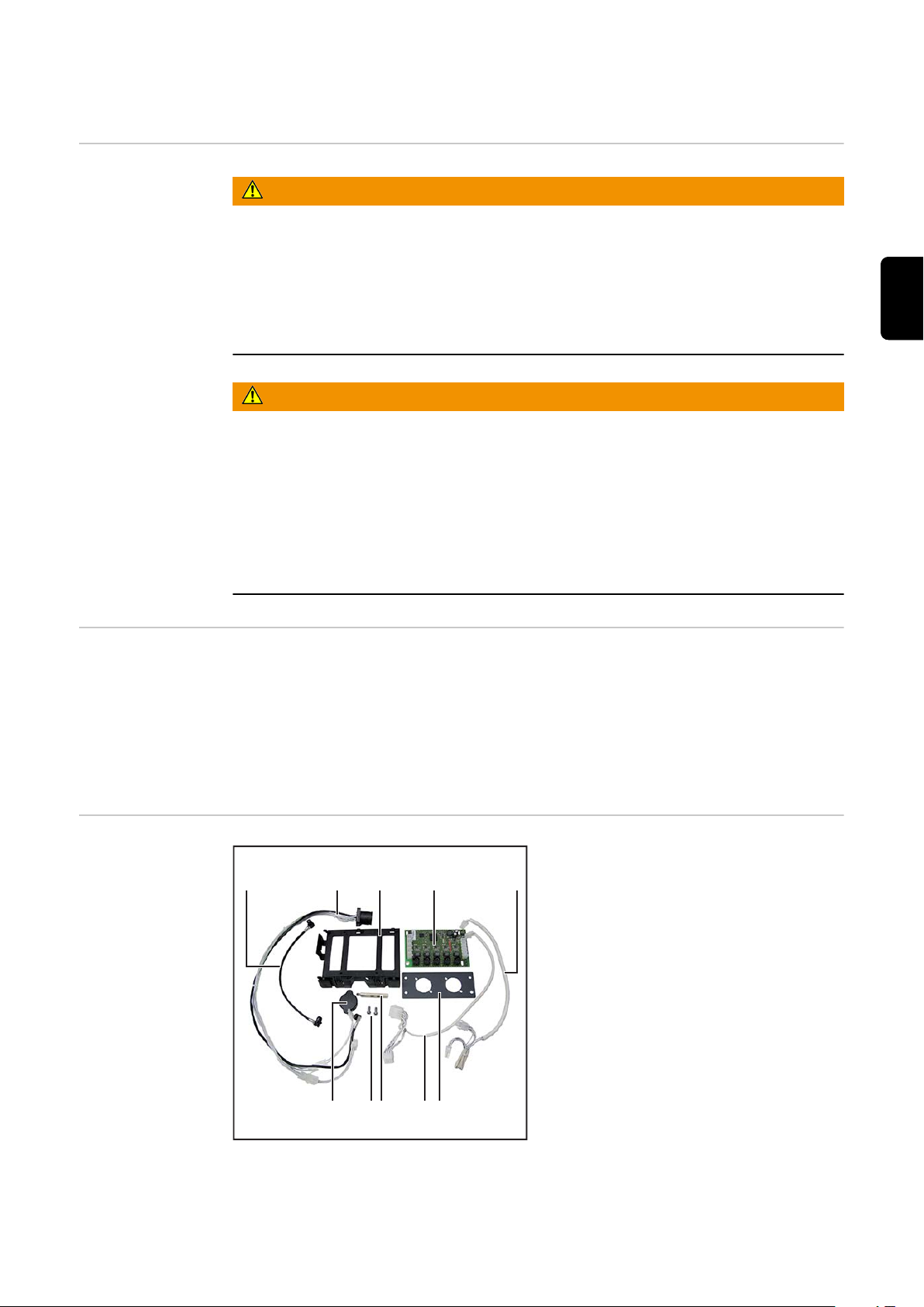
Scope of supply
(1) 1x black cable
(2) 1x black/white cable harness
(3) 1x PC board holder
(4) 1x SCRATSW PC board
(5) 1x 4p/4p cable harness
(6) 1x mounting plate
(7) 1x 2p/8p cable harness
(8) 1x brass spacer
(9) 2x TX25 screws
(10) 1x blanking cover
Not shown:
1x installation instructions
13
Page 14

Note on PC
board population
The SCRATSW PC board is populated differently depending on the version:
Tools required
SCRATSW PC board with 5 SpeedNet connections
SCRATSW PC board with 4 SpeedNet connections
In these Installation Instructions, the SCRATSW PC board with 5 SpeedNet
connections has been used.
TX25 Torx screwdriver
-
8 mm socket wrench
-
Diagonal cutting pliers
-
14
Page 15
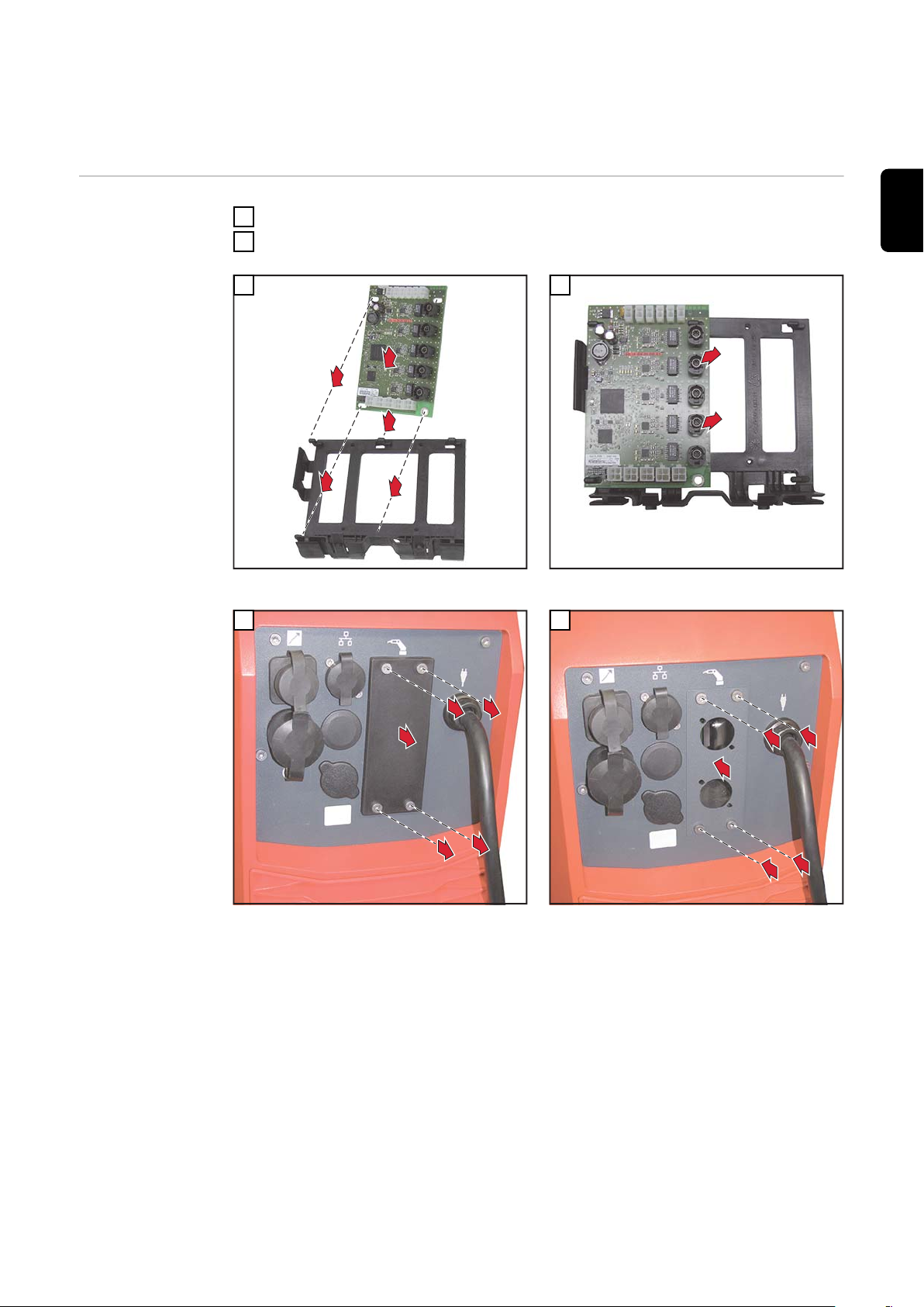
Installing the OPT/i TPS 4x Switch SpeedNet on
1
1
1
1
2
5
4
3
2
3
1
6
4
the rear of the device
Preparations
Switch off the power source and disconnect it from the mains
1
Remove the right side panel from the power source
2
3
Fit the PC board into the holder as illustrated
5
4
Slide the PC board to the right and secure in the
holder
6
EN
Remove the plate on the rear
Fit the mounting plate, tightening torque = 3 Nm
15
Page 16

A
B
C
3
1
2
7
(1)
SMB5000
1
NT241
NT601
(3)
(2)
(4)
5
3
3
4
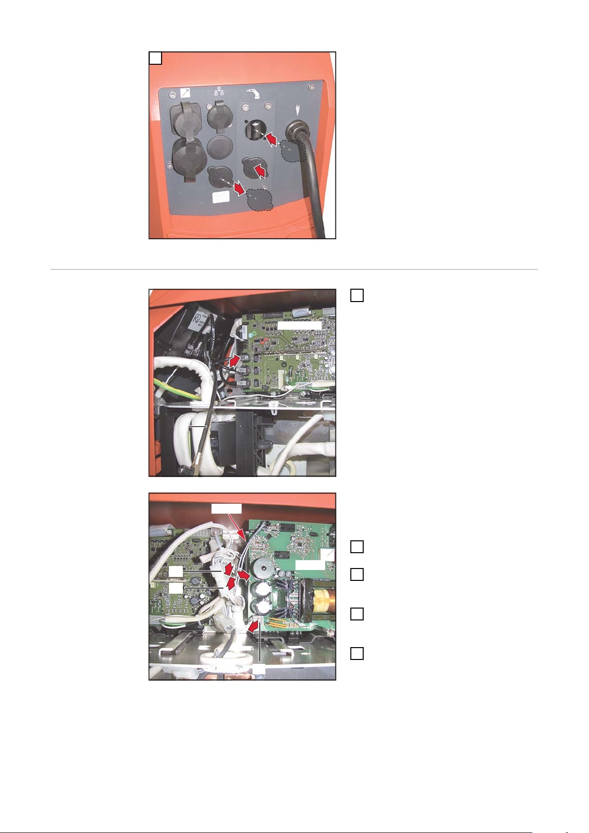
Fit the blanking cover
The SpeedNet connection socket may
be fitted to any of the three locations:
A, B or C. Do not fit a blanking cover to
the desired location.
Installing the
OPT/i TPS 4x
Switch SpeedNet on the rear
Connect the black cable (1) to the
1
free connector on the SMB5000
PC board
IMPORTANT! If there is no free connector available on the SMB5000 PC
board (e.g. with robot interface
present):
Disconnect the robot interface ca-
-
ble from the SMB5000 PC board
Connect the robot interface cable
-
to the SCRATSW PC board
The NT241 PC board is underneath the
NT601 PC board.
Detach the 8-pin cable (2) from the
2
NT241 PC board
Connect the 2p/8p cable harness
3
(3) from the installation set to the
8-pin cable (2)
Connect the 2p/8p cable harness
4
(3) to the NT241 PC board
Detach the 4-pin cable (4) from
5
the NT601 PC board
16
Page 17

NT601
(5)
(4)
6
7
7
Connect the 4p/4p cable harness
SCRATSW
(6) (1)
X10
X11
X12
X13
X14
8
9
9
(1) (5)
SCRATSW
(3)(7)
X10
12
11
13
10
6
(5) to the NT601 PC board
Connect the 4p/4p cable harness
7
(5) to the 4-pin cable (4)
Guide the black cable (1) through
8
the PC board holder
Push in the PC board (6) with PC
9
board holder until it engages for
the second time
EN
Screw in the brass spacer (7)
10
Tightening torque = 1.8 Nm
Connect the black cable (1) to the
11
SCRATSW PC board
Connect the 2p/8p cable harness
12
(3) to the SCRATSW PC board
Connect the 4p/4p cable harness
13
(5) to the SCRATSW PC board
17
Page 18

(8)
14
IMPORTANT! When inserting the
15
15
(8)
18
16
17
SpeedNet connection socket, ensure
that the side marked "TOP" is at the
top.
Starting from the inside, push the
14
SpeedNet connection socket of
the black/white cable harness (8)
through the free opening on the rear of the power source
Secure the SpeedNet connection
15
socket using the two screws from
the installation set
Tightening torque = 1.8 Nm
And finally...
16
17
18
Bind cables together with cable ties
1
Attach the right side panel to the power source
2
Connect the black cable from the
black/white cable harness (8) to
the SCRATSW PC board
Connect the white 4-pin cable
from the black/white cable harness
(8) to the SCRATSW PC board
Connect the white 2-pin cable
from the black/white cable harness
(8) to the SCRATSW PC board
18
Page 19

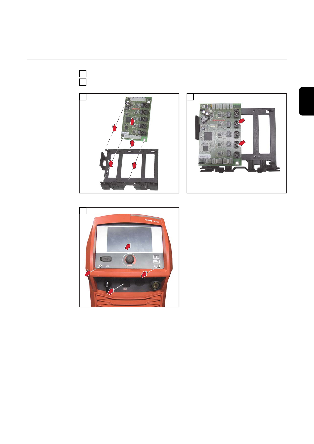
Installing the OPT/i TPS 4x Switch SpeedNet on
1
1
1
1
4
2
3
the front of the device
Preparations
Switch off the power source and disconnect it from the mains
1
Remove the right side panel from the power source
2
3
Fit the PC board into the holder as illustrated
5
4
Slide the PC board to the right and secure in the
holder
EN
Remove the two TX25 screws
Fold the control panel outwards
Remove the blanking cover from the inside
19
Page 20

Installing the
(1)
SMB5000
1
NT241
NT601
(3)
(2)
(4)
5
3
3
4
NT601
(5)
(4)
6
7
7
OPT/i TPS 4x
Switch SpeedNet on the front
Connect the black cable (1) to the
1
free connector on the SMB5000
PC board
IMPORTANT! If there is no free connector available on the SMB5000 PC
board (e.g. with robot interface
present):
Disconnect the robot interface ca-
-
ble from the SMB5000 PC board
Connect the robot interface cable
-
to the SCRATSW PC board
The NT241 PC board is underneath the
NT601 PC board.
Detach the 8-pin cable (2) from the
2
NT241 PC board
Connect the 2p/8p cable harness
3
(3) from the installation set to the
8-pin cable (2)
Connect the 2p/8p cable harness
4
(3) to the NT241 PC board
Detach the 4-pin cable (4) from
5
the NT601 PC board
Connect the 4p/4p cable harness
6
(5) to the NT601 PC board
Connect the 4p/4p cable harness
7
(5) to the 4-pin cable (4)
20
Page 21

SCRATSW
(6) (1)
X10
X11
X12
X13
X14
8
9
9
Guide the black cable (1) through
(1) (5)
SCRATSW
(3)(7)
X10
12
11
13
10
11
8
the PC board holder
Push in the PC board (6) with PC
9
board holder until it engages for
the second time
Screw in the brass spacer (7)
10
Tightening torque = 1.8 Nm
Connect the black cable (1) to the
11
SCRATSW PC board
Connect the 2p/8p cable harness
12
(3) to the SCRATSW PC board
Connect the 4p/4p cable harness
13
(5) to the SCRATSW PC board
EN
IMPORTANT! When inserting the
SpeedNet connection socket, ensure
that the side marked "TOP" is at the
top.
Starting from the inside, push the
14
SpeedNet connection socket of
the black/white cable harness (8)
through the free opening on the
front of the power source
21
Page 22

15
15
Secure the SpeedNet connection
16
12
(8)
19
17
15
socket using the two screws from
the installation set
Tightening torque = 1.8 Nm
Attach the cover
16
And finally...
17
18
19
Bind cables together with cable ties
1
Fit the control panel with two TX25 screws
2
Tightening torque = 3 Nm
Attach the right side panel to the power source
3
Connect the black 2-pin cable
from the black/white cable harness
(8) to the SCRATSW PC board
Connect the white 4-pin cable
from the black/white cable harness
(8) to the SCRATSW PC board
Connect the white 2-pin cable
from the black/white cable harness
(8) to the SCRATSW PC board
22
Page 23
Généralités
(1) (2) (3) (4) (5)
(6)(7)(8)
(9)(10)
4p
4p
8p
2p
8p
4p
Sécurité
AVERTISSEMENT!
Danger dû à une erreur de manipulation et d'erreur en cours d'opération.
Cela peut entraîner des dommages corporels et matériels graves.
Toutes les fonctions et tous les travaux décrits dans le présent document
▶
doivent uniquement être exécutés par du personnel techniquement qualifié.
Ce document doit être lu et compris dans son intégralité.
▶
Lire et comprendre toutes les consignes de sécurité et la documentation uti-
▶
lisateur de cet appareil et de tous les composants périphériques.
AVERTISSEMENT!
Risque d'électrocution.
Cela peut entraîner des dommages corporels et matériels graves.
Avant d'entamer les travaux, déconnecter tous les appareils et composants
▶
concernés et les débrancher du réseau électrique.
S'assurer que tous les appareils et composants concernés ne peuvent pas
▶
être remis en marche.
Après ouverture de l'appareil, s'assurer, à l'aide d'un appareil de mesure ap-
▶
proprié, que les composants à charge électrique (condensateurs, par ex.)
sont déchargés.
FR
Condition préalable
Contenu de la livraison
Pour l'utilisation du kit d'installation OPT/i TPS 4x Switch SpeedNet, le kit d'installation OPT/i TPS 2e SpeedNet Connector (4,100,812) ne doit pas se trouver
sur la source de courant.
Si une interface robot est présente, le câble SpeedNet noir de celle-ci doit être
débranché du circuit imprimé SMB5000 et branché au circuit imprimé
SCRATSW.
(1) 1 x câble noir
(2) 1 x faisceau de câble
noir / blanc
(3) 1 x support de circuit imprimé
(4) 1 x circuit imprimé SCRATSW
(5) 1 x faisceau de câble 4p / 4p
(6) 1 x plaque de montage
(7) 1 x faisceau de câbles 2p / 8p
(8) 1 x pièce d’écartement en laiton
(9) 2 x vis TX25
(10) 1 x fausse prise
Non représenté :
1 x instructions d’installation
23
Page 24

Remarque relative à l'équipement du circuit
imprimé
Selon la version, le circuit imprimé SCRATSW est équipé différemment :
Outils nécessaires
Circuit imprimé SCRATSW avec 5 connecteurs
SpeedNet
Circuit imprimé SCRATSW avec 4 connecteurs
SpeedNet
Pour ces Instructions d‘installation, c'est le circuit imprimé SCRATSW avec
5 connecteurs SpeedNet qui a été utilisé.
Tournevis Torx TX 25
-
Clé à douille SW 8 mm
-
Pince coupante de côté
-
24
Page 25

Montage de l'OPT/i TPS 4x Switch SpeedNet sur
1
1
1
1
2
5
4
3
2
3
1
6
4
la face arrière de l'appareil
Préparation
Désactiver la source de courant et la débrancher du secteur
1
Retirer le panneau latéral droit de la source de courant
2
3
Insérer le circuit imprimé dans le support, comme indiqué sur l’illustration
5
4
Déplacer le circuit imprimé vers la droite et le fixer dans le support
6
FR
Retirer la plaque sur la face arrière
Monter la plaque de montage, couple de serrage
= 3 Nm
25
Page 26
A
B
C
3
1
2
7
(1)
SMB5000
1
NT241
NT601
(3)
(2)
(4)
5
3
3
4
Insérer la fausse prise
Le raccord Speed Net peut être monté
sur l’une des 3 positions A, B ou C. Ne
pas insérer de fausse prise dans la position choisie.
Montage de
l'OPT/
i TPS 4x Switch
SpeedNet sur la
face arrière
Brancher le câble noir (1) au con-
1
necteur libre du circuit imprimé
SMB 5000
IMPORTANT ! Si aucun connecteur
n'est libre sur le circuit imprimé
SMB5000 (par ex. en présence d'une
interface robot) :
Débrancher le câble de l'interface
-
robot du circuit imprimé
SMB5000
Brancher le câble de l'interface ro-
-
bot au circuit imprimé SCRATSW
Le circuit imprimé NT241 se trouve
sous le circuit imprimé NT601.
Débrancher le câble à 8 pôles (2)
2
du circuit imprimé NT241
Raccorder le faisceau de câbles
3
2p / 8p (3) fourni dans le kit d'installation au câble à 8 pôles (2)
Brancher le faisceau de câbles
4
2p / 8p (3) au circuit imprimé
NT241
Débrancher le câble à 4 pôles (4)
5
du circuit imprimé NT601
26
Page 27

NT601
(5)
(4)
6
7
7
Brancher le faisceau de câbles
SCRATSW
(6) (1)
X10
X11
X12
X13
X14
8
9
9
(1) (5)
SCRATSW
(3)(7)
X10
12
11
13
10
6
4p / 4p (5) au circuit imprimé
NT601
Raccorder le faisceau de câbles
7
4p / 4p (5) au câble à 4 pôles (4)
Passer le câble noir (1) au travers
8
du support du circuit imprimé
Insérer le circuit imprimé (6) avec
9
le support du circuit imprimé et le
pousser jusqu'au deuxième déclic
FR
Visser la pièce d'écartement (7) en
10
laiton
couple de serrage = 1,8 Nm
Brancher le câble noir (1) au circuit
11
imprimé SCRATSW
Brancher le faisceau de câbles
12
2p / 8p (3) au circuit imprimé
SCRATSW
Brancher le faisceau de câbles
13
4p / 4p (5) au circuit imprimé
SCRATSW
27
Page 28

(8)
14
IMPORTANT ! Lors de la mise en place
15
15
(8)
18
16
17
du connecteur SpeedNet, veiller à ce
que le marquage « TOP » se trouve en
haut.
Insérer le connecteur SpeedNet du
14
faisceau de câbles noir / blanc (8)
dans l'ouverture libre de l'intérieur
vers l'extérieur sur la face arrière
de la source de courant
Fixer le connecteur SpeedNet à
15
l'aide des 2 vis fournies dans le kit
d'installation
Couple de serrage = 1,8 Nm
Opérations finales
Brancher le câble noir du faisceau
16
de câbles noir / blanc (8) au circuit
imprimé SCRATSW
Brancher le câble à 4 pôles blanc
17
du faisceau de câbles noir / blanc
(8) au circuit imprimé SCRATSW
Brancher le câble à 2 pôles blanc
18
du faisceau de câbles noir / blanc
(8) au circuit imprimé SCRATSW
Fixer le câble à l'aide des attache-câbles
1
Remonter le panneau latéral droit de la source de courant
2
28
Page 29
Montage de l'OPT/i TPS 4x Switch SpeedNet sur
1
1
1
1
4
2
3
la face avant de l'appareil
Préparation
Désactiver la source de courant et la débrancher du secteur
1
Retirer le panneau latéral droit de la source de courant
2
3
Insérer le circuit imprimé dans le support, comme indiqué sur l'illustration
5
4
Déplacer le circuit imprimé vers la droite et le fixer dans le support
FR
Retirer 2 vis TX 25
Rabattre le panneau de commande vers l'extérieur
Retirer la fausse prise de l'intérieur vers l'extérieur
29
Page 30
Montage de
(1)
SMB5000
1
NT241
NT601
(3)
(2)
(4)
5
3
3
4
NT601
(5)
(4)
6
7
7
l'OPT/
i TPS 4x Switch
SpeedNet sur la
face avant
Brancher le câble noir (1) au con-
1
necteur libre du circuit imprimé
SMB 5000
IMPORTANT ! Si aucun connecteur
n'est libre sur le circuit imprimé
SMB5000 (par ex. en présence d'une
interface robot) :
Débrancher le câble de l'interface
-
robot du circuit imprimé
SMB5000
Brancher le câble de l'interface ro-
-
bot au circuit imprimé SCRATSW
Le circuit imprimé NT241 se trouve
sous le circuit imprimé NT601.
Débrancher le câble à 8 pôles (2)
2
du circuit imprimé NT241
Raccorder le faisceau de câbles
3
2p / 8p (3) fourni dans le kit d'installation au câble à 8 pôles (2)
Brancher le faisceau de câbles
4
2p / 8p (3) au circuit imprimé
NT241
Débrancher le câble à 4 pôles (4)
5
du circuit imprimé NT601
Brancher le faisceau de câbles
6
4p / 4p (5) au circuit imprimé
NT601
Raccorder le faisceau de câbles
7
4p / 4p (5) au câble à 4 pôles (4)
30
Page 31
SCRATSW
(6) (1)
X10
X11
X12
X13
X14
8
9
9
Passer le câble noir (1) au travers
(1) (5)
SCRATSW
(3)(7)
X10
12
11
13
10
11
8
du support du circuit imprimé
Insérer le circuit imprimé (6) avec
9
le support du circuit imprimé et le
pousser jusqu'au deuxième déclic
Visser la pièce d'écartement (7) en
10
laiton
couple de serrage = 1,8 Nm
Brancher le câble noir (1) au circuit
11
imprimé SCRATSW
Brancher le faisceau de câbles
12
2p / 8p (3) au circuit imprimé
SCRATSW
Brancher le faisceau de câbles
13
4p / 4p (5) au circuit imprimé
SCRATSW
FR
IMPORTANT ! Lors de la mise en place
du connecteur SpeedNet, veiller à ce
que le marquage « TOP » se trouve en
haut.
Insérer le connecteur SpeedNet du
14
faisceau de câbles noir / blanc (8)
dans l'ouverture libre de l'intérieur
vers l'extérieur sur la face avant de
la source de courant
31
Page 32

15
15
Fixer le connecteur SpeedNet à
16
12
(8)
19
17
15
l'aide des 2 vis fournies dans le kit
d'installation
Couple de serrage = 1,8 Nm
Replacer le cache
16
Étapes finales
Brancher le câble à 2 pôles noir du
17
faisceau de câbles noir / blanc (8)
au circuit imprimé SCRATSW
Brancher le câble à 4 pôles blanc
18
du faisceau de câbles noir / blanc
(8) au circuit imprimé SCRATSW
Brancher le câble à 2 pôles blanc
19
du faisceau de câbles noir / blanc
(8) au circuit imprimé SCRATSW
Fixer le câble à l’aide des attache-câbles
1
Monter le panneau de commande avec 2 vis TX25
2
Couple de serrage = 3 Nm
Remonter le panneau latéral droit de la source de courant
3
32
Page 33

FR
33
Page 34

34
Page 35

FR
35
Page 36
Fronius International GmbH
Froniusstraße 1
4643 Pettenbach
Austria
contact@fronius.com
www.fronius.com
Under www.fronius.com/contact you will find the adresses
of all Fronius Sales & Service Partners and locations.
spareparts.fronius.com
SPAREPARTS
ONLINE
 Loading...