


/ Perfect Charging / Perfect Welding / Solar Energy
OPT/i TPS 2. SpeedNet Connector
OPT/i TPS 2nd SpeedNet Connector
OPT/i TPS 2e SpeedNet Connector
Einbauanleitung
DEENFR
MIG/MAG-Stromquelle
Fitting instructions
MIG/MAG Power source
Instructions d'installation
Source de courant MIG/MAG
42,0410,2044 002-28092015

0

Allgemeines
DE
Sicherheit
Lieferumfang
WARNUNG! Ein elektrischer Schlag kann tödlich sein. Vor Öffnen des Gerätes
- Netzschalter in Stellung - O - schalten
- Gerät vom Netz trennen
- ein verständliches Warnschild gegen Wiedereinschalten anbringen
- mit Hilfe eines geeigneten Messgerätes sicherstellen, dass elektrisch geladene Bauteile (z.B. Kondensatoren) entladen sind
WARNUNG! Fehlerhaft durchgeführte Arbeiten können schwerwiegende Personen- und Sachschäden verursachen. Nachfolgend beschriebene Tätigkeiten dürfen nur von geschultem Fachpersonal durchgeführt werden! Beachten Sie das
Kapitel „Sicherheitsvorschriften“ in der Bedienungsanleitung der Stromquelle und
der Systemkomponenten.
(1) 1 Schaltplan
(2) 1 Kabelbaum schwarz / weiß
(3) 1 Abdeckung
(1)
(4) 4 Kabelbinder
(5) 2 Schrauben TX20
ohne Abbildung:
Erforderliche
Werkzeuge
1 Einbauanleitung
(2) (3) (4) (5)
OPT/i TPS 2. SpeedNetConnector
- Schraubendreher TX 25
- Schraubendreher TX 20
1

OPT/i TPS 2. SpeedNet Connector an der GeräteRückseite einbauen
Vorbereitung Stromquelle ausschalten und vom Netz trennen
OPT/i TPS
2. SpeedNet
1
Rechten Seitenteil der Stromquelle entfernen
2
(1)
1
Connector an der
Geräte-Rückseite
2
einbauen
1
2
(2)
(1)
3
4
3
3
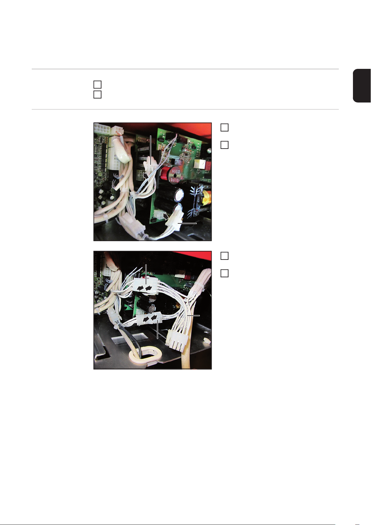
Kabel (1) vom Stecker X2 am Print
NT241 abstecken
Kabel (2) vom Stecker X1 am Print
NT601 abstecken
Kabel (1) mit dem entsprechenden Gegenstück vom Kabelbaum (3) zusammenstecken
Kabel (2) mit dem entsprechenden Gegenstück vom Kabelbaum (3) zusammenstecken
4
4
(3)
(2)
2

6
(5)
(4)
4-poligen Stecker (4) vom Kabelbaum
5
am Print NT601 an X1 anstecken
8-poligen Stecker (5) vom Kabelbaum
6
DE
am Print NT241 an X2 anstecken
5
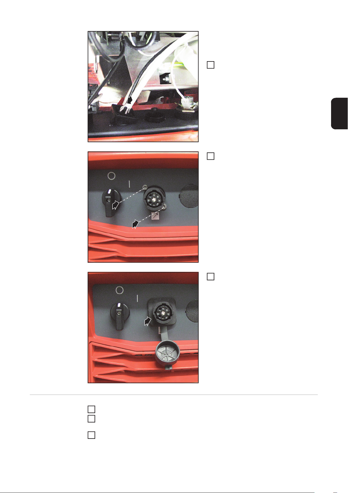
Schwarzes Kabel (6) vom Kabelbaum
7
am Print SMB an X23 anstecken
(6)
7
“TOP“
(7) (8) (9)
Blindabdeckung an der Rückseite ent-
8
fernen
WICHTIG! Beim Einsetzen des SpeedNet-Anschlusses darauf achten, dass
die Markierung “TOP“ oben ist!
SpeedNet-Anschluss (8) vom Kabel-
9
baum von innen nach außen in die Öffnung einsetzen
SpeedNet-Anschluss (8) mit den 2
10
Schrauben TX20 aus dem Lieferumfang fixieren
Anzugsmoment = 1,8 Nm
3

Abdeckung (10) über dem SpeedNet-
11
Anschluss anbringen
11
(10)
Kabel mittels Kabelinder fixieren
12
Rechten Seitenteil der Stromquelle
13
montieren
12
12
12
12
4

OPT/i TPS 2. SpeedNet Connector an der GeräteVorderseite einbauen
Vorbereitung Stromquelle ausschalten und vom Netz trennen
OPT/i TPS
2. SpeedNet
Connector an der
Geräte-Vorderseite einbauen
1
Rechten Seitenteil der Stromquelle entfernen
2
(1)
1
2
(2)
1
2
DE
Kabel (1) vom Stecker X2 am Print
NT241 abstecken
Kabel (2) vom Stecker X1 am Print
NT601 abstecken
Kabel (1) mit dem entsprechenden Ge-
(1)
3
genstück vom Kabelbaum (3) zusammenstecken
Kabel (2) mit dem entsprechenden Ge-
4
3
3
genstück vom Kabelbaum (3) zusammenstecken
4
4
(3)
(2)
5

6
(5)
(4)
4-poligen Stecker (4) vom Kabelbaum
5
am Print NT601 an X1 anstecken
8-poligen Stecker (5) vom Kabelbaum
6
am Print NT241 an X2 anstecken
5
Schwarzes Kabel (6) vom Kabelbaum
7
am Print SMB an X23 anstecken
7
(6)
2 Schrauben TX25 entfernen
8
Bedienpanel heraus klappen
Blindabdeckung von innen nach außen
entfernen
3
1
4
2
6

WICHTIG! Beim Einsetzen des 2. SpeedNet-Anschlusses darauf achten, dass die
Markierung „TOP“ oben ist.
Anschluss SpeedNet vom Kabelbaum
9
DE
schwarz / weiß (8) an der Vorderseite
der Stromquelle von innen nach außen
in die freie Öffnung einsetzen
4
1
Anschluss SpeedNet mit den 2
10
Schrauben aus dem Lieferumfang des
Einbau-Sets befestigen
Anzugsmoment = 1,8 Nm
15
15
16
Abdeckung anbringen
11
Abschließende
Tätigkeiten
Kabel mit Kabelbinder fixieren
1
Bedienpanel mit 2 Schrauben TX25 montieren
2
Anzugsmoment = 3 Nm
Rechten Seitenteil der Stromquelle montieren
3
7

8

General
Safety
Scope of supply
WARNING! An electric shock can be fatal. Before opening the device
- Turn the mains switch to the "O" position
- Unplug the machine from the mains
- Put up an easy-to-understand warning sign to stop anybody inadvertently
switching it back on again
- Using a suitable measuring instrument, check to make sure that electrically
charged components (e.g. capacitors) have discharged
WARNING! Work that is carried out incorrectly can cause serious injury and damage. The following activities must only be carried out by trained and qualified personnel. Read the "Safety rules" chapter in the power source and system
components operating instructions.
(1) 1 circuit diagram
(2) 1 black/white cable harness
(3) 1 cover
(1)
(4) 4 cable ties
(5) 2 TX20 screws
Not shown:
EN
(2) (3) (4) (5)
OPT/i TPS 2nd SpeedNetConnector
Tools required - TX 25 screwdriver
- TX 20 screwdriver
1 installation instructions
9

Installing the OPT/i TPS 2nd SpeedNet connector on
the rear of the device
Preparations Switch off the power source and disconnect it from the mains
Installing the
OPT/i TPS
1
Remove the right side panel from the power source
2
(1)
Unplug cable (1) from the X2 connec-
1
tor on the NT241 PC board
2nd SpeedNet
Unplug cable (2) from the X1 connec-
connector on the
rear of the device
1
2
2
tor on the NT601 PC board
(2)
Connect cable (1) to respective coun-
(1)
3
terpart of the cable harness (3)
Connect cable (2) to respective coun-
4
terpart of the cable harness (3)
3
3
4
4
(3)
(2)
10

6
(5)
Plug the 4-pin connector (4) on the ca-
5
ble harness into X1 on the NT601 PC
board
Plug the 8-pin connector (5) on the ca-
6
ble harness into X2 on the NT241 PC
board
(6)
5
EN
(4)
Plug the black cable (6) on the cable
7
harness into X23 on the SMB PC
board
7
“TOP“
(7) (8) (9)
Remove blanking cover on the rear
8
IMPORTANT! When inserting the
SpeedNet connection socket, ensure
that the side marked "TOP" is at the
top.
Insert the SpeedNet connector (8) on
9
the cable harness into the opening
from the inside
Secure the SpeedNet connector (8)
10
using the 2
TX20 screws supplied
Tightening torque = 1.8 Nm
11

Fit cover (10) over the SpeedNet
11
connector
11
(10)
Secure cables using cable ties
12
Attach the right side panel to the power
13
source
12
12
12
12
12
Installing the OPT/i TPS 2nd SpeedNet connector on
the front of the device
Preparations Switch off the power source and disconnect it from the mains
Installing the
OPT/i
1
Remove the right side panel from the power source
2
(1)
Unplug cable (1) from the X2 connec-
1
tor on the NT241 PC board
TPS 2nd Speed-
Unplug cable (2) from the X1 connec-
Net connector on
the front of the
2
tor on the NT601 PC board
device
1
2
(2)
Connect cable (1) to respective coun-
(1)
3
terpart of the cable harness (3)
Connect cable (2) to respective coun-
4
terpart of the cable harness (3)
3
3
EN
4
4
(3)
(2)
13

6
(5)
(4)
Plug the 4-pin connector (4) on the ca-
5
ble harness into X1 on the NT601 PC
board
Plug the 8-pin connector (5) on the ca-
6
ble harness into X2 on the NT241 PC
board
5
Plug the black cable (6) on the cable
7
harness into X23 on the SMB PC
board
7
(6)
Remove the two TX25 screws
8
Fold the control panel outwards
Remove the blanking cover from the
inside
3
1
4
2
14

IMPORTANT! When inserting the 2nd
connection socket, ensure that the side
marked "TOP" is at the top.
Starting from the inside, push the
9
SpeedNet connection socket from the
black/white cable harness (8) through
the free opening on the front of the po-
EN
wer source
4
1
Secure the SpeedNet connection so-
10
cket using the two screws from the installation set
Tightening torque = 1.8 Nm
15
15
16
Attach the cover
11
And finally... Bind cables together with cable ties
1
Fit the control panel with two TX25 screws
2
Tightening torque = 3 Nm
Attach the right side panel to the power source
3
15

16

Généralités
Sécurité
Contenu de la livraison
AVERTISSEMENT ! Un choc électrique peut être mortel. Avant d'ouvrir l'appareil
- commuter l’interrupteur du secteur en position - O -
- débrancher l'appareil du secteur
- apposer un panneau d'avertissement compréhensible afin de prévenir toute
remise en marche
- s'assurer, à l'aide d'un appareil de mesure approprié, que les composants à
charge électrique (condensateurs par ex.) sont déchargés
AVERTISSEMENT ! Les erreurs en cours d'opération peuvent entraîner des
dommages corporels et matériels graves. Les opérations décrites ci-après
doivent être effectuées exclusivement par du personnel qualifié et formé ! Respecter les prescriptions du chapitre « Consignes de sécurité » figurant dans les
Instructions de service de la source de courant et des composants du système.
(1) 1 schéma de connexions
(2) 1 faisceau de câbles noir / blanc
(3) 1 cache
(1)
(4) 4 attache-câbles
(5) 2 vis TX20
Non illustrées :
FR
Outils nécessaires
Instructions d’installation
(2) (3) (4) (5)
2e connecteur SpeedNet OPT/i TPS
- Tournevis TX 25
- Tournevis TX 20
17

Monter le 2e connecteur SpeedNet OPT/i TPS sur la
face arrière de l’appareil
Préparation Désactiver la source de courant et la débrancher du secteur
Monter le
2e connecteur
1
Retirer le panneau latéral droit de la source de courant
2
(1)
1
Débrancher le câble (1) de la fiche X2
sur le circuit imprimé NT241
SpeedNet OPT/i
Débrancher le câble (2) de la fiche X1
TPS sur la face arrière de l’appareil
1
2
2
sur le circuit imprimé NT601
(2)
Raccorder le câble (1) à son pendant
(1)
3
sur le faisceau de câbles (3)
Raccorder le câble (2) à son pendant
4
sur le faisceau de câbles (3)
3
3
4
4
(3)
(2)
18

6
(5)
Raccorder la fiche 4 pôles (4) du fais-
5
ceau de câbles à X1 sur le circuit imprimé NT601
Raccorder la fiche 8 pôles (5) du fais-
6
ceau de câbles à X2 sur le circuit imprimé NT241
5
(6)
7
(4)
“TOP“
Raccorder le câble noir (6) du faisceau
7
de câbles à X23 sur le circuit imprimé
SMB
Retirer la fausse prise sur la face arriè-
8
re
FR
(7) (8) (9)
IMPORTANT ! Lors de la mise en place du connecteur SpeedNet, veiller à
ce que le marquage « TOP » se trouve
en haut !
Insérer le connecteur SpeedNet (8) du
9
faisceau de câbles de l’intérieur vers
l’extérieur dans l’ouverture
Fixer le connecteur SpeedNet (8) avec
10
les 2
vis TX20 fournies
Couple de serrage = 1,8 Nm
19

Poser le cache (10) au-dessus du
11
connecteur SpeedNet
11
(10)
Fixer le câble au moyen des attache-
12
câbles
Remonter le panneau latéral droit de la
13
12
source de courant
12
12
12
20

Monter le 2e connecteur SpeedNet OPT/i TPS sur la
face avant de l’appareil
Préparation Désactiver la source de courant et la débrancher du secteur
Monter le
2e connecteur
1
Retirer le panneau latéral droit de la source de courant
2
(1)
1
Débrancher le câble (1) de la fiche X2
sur le circuit imprimé NT241
SpeedNet OPT/i
Débrancher le câble (2) de la fiche X1
TPS sur la face
avant de l’appa-
2
sur le circuit imprimé NT601
reil
1
2
(2)
Raccorder le câble (1) à son pendant
(1)
3
sur le faisceau de câbles (3)
Raccorder le câble (2) à son pendant
4
sur le faisceau de câbles (3)
3
3
FR
4
4
(3)
(2)
21

6
(5)
(4)
Raccorder la fiche 4 pôles (4) du fais-
5
ceau de câbles à X1 sur le circuit imprimé NT601
Raccorder la fiche 8 pôles (5) du fais-
6
ceau de câbles à X2 sur le circuit imprimé NT241
5
Raccorder le câble noir (6) du faisceau
7
de câbles à X23 sur le circuit imprimé
SMB
7
(6)
Retirer 2 vis TX25
8
Rabattre le panneau de commande
vers l’extérieur
Retirer la fausse prise de l’intérieur
3
1
4
2
vers l’extérieur
22
IMPORTANT ! Lors de la mise en place du
2e connecteur SpeedNet, veiller à ce que le
marquage « TOP » se trouve en haut !
Insérer le connecteur SpeedNet du fai-
9
sceau de câbles noir / blanc (8) dans
l’ouverture libre de l’intérieur vers
l’extérieur sur la face avant de la source de courant
4
1
FR
Fixer le connecteur SpeedNet à l’aide
10
des 2 vis fournies dans le kit d’installation
Couple de serrage = 1,8 Nm
15
15
16
Replacer le cache
11
Étapes finales Fixer le câble à l’aide des attache-câbles
1
Monter le panneau de commande avec 2 vis TX25
2
Couple de serrage = 3 Nm
Remonter le panneau latéral droit de la source de courant
3
23

FRONIUS INTERNATIONAL GMBH
Froniusplatz 1, A-4600 Wels, Austria
Tel: +43 (0)7242 241-0, Fax: +43 (0)7242 241-3940
E-Mail: sales@fronius.com
www.fronius.com
www.fronius.com/addresses
Under http://www.fronius.com/addresses you will find all addresses
of our Sales & service partners and Locations
 Loading...