


Installation
Instructions
OPT/i TPS 2nd M12 Current Bolt
DE
EN-US
Installationsanleitung
Installation instructions
42,0410,2912 001-06032023


Inhaltsverzeichnis
Allgemeines 4
Voraussetzung 4
Lieferumfang 4
Erforderliche Werkzeuge 4
OPT/i TPS 2nd M12 Current Bolt einbauen 5
Sicherheit 5
Vorbereitung 5
OPT/i TPS 2nd M12 Current Bolt einbauen 6
Abschließende Tätigkeiten 8
Kabel an der zweiten Strombuchse festschrauben 9
Kabel an der zweiten Strombuchse festschrauben 9
DE
3

Allgemeines
(1)
(2)
(3)
(4)
(5)
(6)
(7)
(10)
(11)
(8)
(9)
Voraussetzung Für Montage und Betrieb der Option OPT/i TPS 2nd M12 Current Bolt muss die
Option OPT/i TPS M12 Current Bolts (4,100,784) in der Stromquelle eingebaut
sein.
Lieferumfang
Erforderliche
Werkzeuge
(1) 2 Stromschienen
(2) Strombuchse
(3) Isolierbuchse
(4) Isolierscheibe
(5) Strombuchsen-Abdeckung
(6) Sechskant-Schraube M12 x 20 mm, SW 19 mm
(7) Sechskant-Schrauben M12 x 30 mm, SW 19 mm
(8) 2 Messingscheiben
(9) 2 Tellerfedern
(10) Sechskant-Mutter M24, SW 32 mm
(11) Scheibe A13
Torx Schraubendreher TX 25
-
Gabelschlüssel SW 19 mm
-
Gabelschlüssel SW 32 mm
-
Drehmomentschlüssel
-
Steckschlüsseleinsatz SW 19
-
Steckschlüsseleinsatz SW 32
-
4

OPT/i TPS 2nd M12 Current Bolt einbauen
DE
Sicherheit
WARNUNG!
Fehlbedienung und fehlerhaft durchgeführte Arbeiten können schwerwiegende
Personen- und Sachschäden verursachen.
Alle in diesem Dokument beschriebenen Arbeiten und Funktionen dürfen
▶
nur von geschultem Fachpersonal ausgeführt werden.
Alle in diesem Dokument beschriebenen Arbeiten und Funktionen dürfen
▶
nur ausgeführt werden, wenn dieses Dokument vollständig gelesen und verstanden wurde.
Alle in diesem Dokument beschriebenen Arbeiten und Funktionen dürfen
▶
nur ausgeführt werden, wenn sämtliche Bedienungsanleitungen der Systemkomponenten, insbesondere Sicherheitsvorschriften vollständig gelesen und
verstanden wurden.
WARNUNG!
Ein elektrischer Schlag kann tödlich sein.
Vor Beginn der Arbeiten
Netzschalter der Stromquelle in Stellung - O - schalten
▶
Stromquelle vom Netz trennen
▶
sicherstellen, dass die Stromquelle bis zum Abschluss aller Arbeiten vom
▶
Netz getrennt bleibt
Nach dem Öffnen des Gerätes mit Hilfe eines geeigneten Messgerätes si-
▶
cherstellen, dass elektrisch geladene Bauteile (z.B. Kondensatoren) entladen
sind.
Vorbereitung
WARNUNG!
Unzureichende Schutzleiter-Verbindung kann schwerwiegende Personen- und
Sachschäden verursachen.
Die Gehäuse-Schrauben stellen eine geeignete Schutzleiter-Verbindung für die
Erdung des Gehäuses dar.
Die Gehäuse-Schrauben dürfen keinesfalls durch andere Schrauben ohne
▶
zuverlässige Schutzleiter-Verbindung ersetzt werden.
VORSICHT!
Verletzungsgefahr durch heiße Systemkomponenten.
Vor Beginn der Arbeiten alle heißen Systemkomponenten auf Zimmertempe-
▶
ratur (+25 °C, +77 °F) abkühlen lassen, beispielsweise:
Kühlmittel,
wassergekühlte Systemkomponenten,
Antriebsmotor des Drahtvorschubes.
Von vorne gesehen, den rechten Seitenteil der Stromquelle entfernen
1
2 Schrauben TX 25 des Bedienpanels entfernen
2
Bedienpanel aus dem Gehäuse der Stromquelle herausklappen
3
5

OPT/i TPS 2nd
1
2
2
3
4
M12 C
Bolt einbauen
urrent
Blindabdeckung entfernen
1
Sechskant-Schraube entfernen
2
SW 19 mm
Strombuchse in Isolierbuchse einsetzen
3
Strombuchse und Isolierbuchse von vorne in die Öffnung einsetzen
4
6
6
5
7
8
Isolierscheibe auf die Strombuchse aufsetzen
5
Strombuchse mit Sechskantmutter fixieren
6
SW 32 mm, Anzugsmoment = 25 Nm
2 Stromschienen an der Strombuchse positionieren
7
Stromschienen mit Sechskant-Schraube M12 x 20 mm + Tellerfeder + Schei-
8
be A13 an der Strombuchse anschrauben - noch nicht festziehen!
SW 19 mm
DE
WICHTIG! Die Wölbung der Tellerfeder muss zum Schraubenkopf zeigen, die
nicht-abgerundete Seite der Scheibe muss zur Tellerfeder zeigen.
7

9
9
1
0
Sechskant-Schraube aus Arbeitsschritt 2 mit Buchsenstern, Tellerfeder und
9
Scheibe an der freien Strombuchse aufschrauben und festziehen
SW 19 mm, Anzugsmoment = 15 Nm
Sechskant-Schraube an der 2. Strombuchse festziehen
10
SW 19 mm, Anzugsmoment = 15 Nm
Abschließende
Tätigkeiten
Bedienpanel in seine Originalposition bringen
1
Bedienpanel mit 2 Schrauben TX 25 an der Stromquelle festschrauben
2
Rechten Seitenteil der Stromquelle in die Stromquelle einsetzen und mit 5
3
Schrauben TX 25 festschrauben
8

Kabel an der zweiten Strombuchse festschrauben
(2)
(1)
(2)
(2)
(3)
(4)
(5)
(6)
3
1
DE
Kabel an der
zweiten Strombuchse festschrauben
WICHTIG! Die Strombuchsen-Abdeckung (1) muss eng am Anschlusskabel an-
liegen. Falls notwendig, die Strombuchsen-Abdeckung (1) an einer der Markierungen (2) abschneiden.
Strombuchsen-Abdeckung (1) an einer der Markierungen (2) abschneiden
1
Strombuchsen-Abdeckung (1) auf das Anschlusskabel schieben
2
Den Kabelschuh vom Anschlusskabel wie folgt mit dem mitgelieferten Befes-
3
tigungsmaterial an der Strombuchse festschrauben:
Sechskant-Schraube M12 x 30 mm - Tellerfeder (6) - Messingscheibe (5) - Kabelschuh (4) - Messingscheibe (3)
SW 19 mm, Anzugsmoment = 15 - 35 Nm
9

4
Strombuchsen-Abdeckung über die Strombuchse schieben
4
10

Table of contents
General 12
Requirements 12
Scope of supply 12
Tools required 12
Installing the OPT/i TPS M12 Current Bolt 13
Safety 13
Preparation 13
Installing the OPT/i TPS M12 Current Bolt 14
Final Tasks 16
Screwing the cable onto the second current socket 17
Screwing the cable onto the second current socket 17
EN-US
11

General
(1)
(2)
(3)
(4)
(5)
(6)
(7)
(10)
(11)
(8)
(9)
Requirements To install and operate the OPT/i TPS 2nd M12 Current Bolt option, the OPT/i TPS
M12 Current Bolts option (4,100,784) must be installed in the power source.
Scope of supply
Tools required
(1) 2 x busbars
(2) Current socket
(3) Insulating socket
(4) Insulating washer
(5) Current socket cover
(6) M12 x 20 mm hexagonal bolt, size 19 mm
(7) M12 x 30 mm hexagonal bolts, size 19 mm
(8) 2 x brass washers
(9) 2 x disk springs
(10) M24 hexagonal nut, size 32 mm
(11) Washer A13
Torx screwdriver, TX 25
-
19 mm wrench
-
32 mm wrench
-
Torque wrench
-
19 mm socket wrench
-
32 mm socket wrench
-
12

Installing the OPT/i TPS M12 Current Bolt
Safety
WARNING!
Incorrect operation and incorrectly performed work can cause serious injury
and damage to property.
All the work and functions described in this document must only be carried
▶
out by trained and qualified personnel.
All work and functions described in this document must only be performed
▶
once you have read and understood this document in full.
Do not perform the work and functions described in this document until you
▶
have thoroughly read and understood all the Operating Instructions for the
system components, especially the safety rules.
WARNING!
An electric shock can be fatal.
Before beginning the work
Switch the power switch on the power source to - O -
▶
Disconnect the power source from the grid
▶
Ensure that the power source remains disconnected from the grid until all
▶
work is complete
After opening the device, use a suitable measuring tool to ensure that
▶
electrically charged components (e.g. capacitors) are discharged.
EN-US
Preparation
WARNING!
An inadequate ground conductor connection can cause serious injury and damage to property.
The housing screws act as a ground conductor connection for grounding the
housing.
The housing screws must not under any circumstances be replaced by other
▶
screws without a reliable ground conductor connection.
CAUTION!
Risk of injury from hot system components.
Before starting work, allow all hot system components to cool to room tem-
▶
perature (+25 °C, +77 °F), for example:
Coolant,
water-cooled system components,
wirefeeder drive motor.
Looking from the front, take the right side panel off the power source
1
Remove the two TX 25 screws on the control panel
2
Fold out the control panel from the power source
3
13
Installing the
1
2
2
3
4
OPT/i TPS M12
Current Bolt
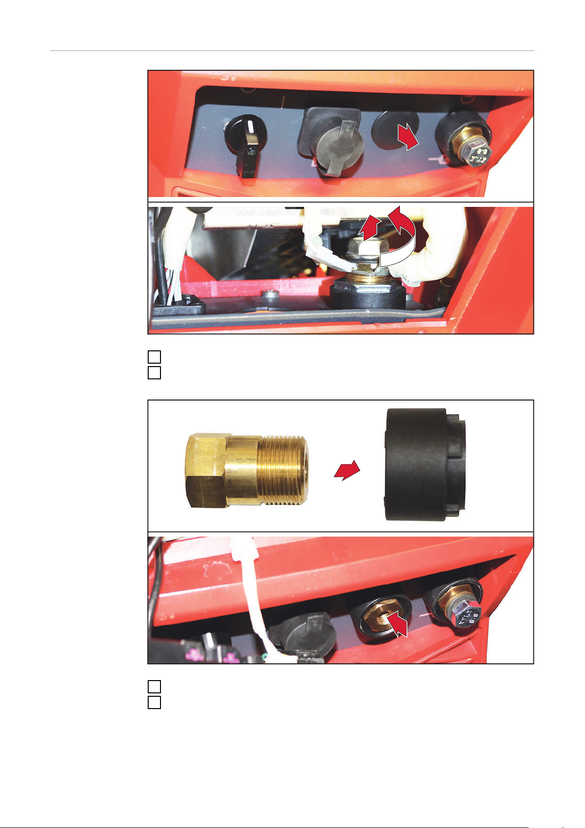
Remove the dummy cover
1
Remove the hexagonal bolt
2
size 19 mm
14
Insert the current socket into the insulating socket
3
Insert the current socket and insulating socket into the opening from the
4
front

6
5
7
8
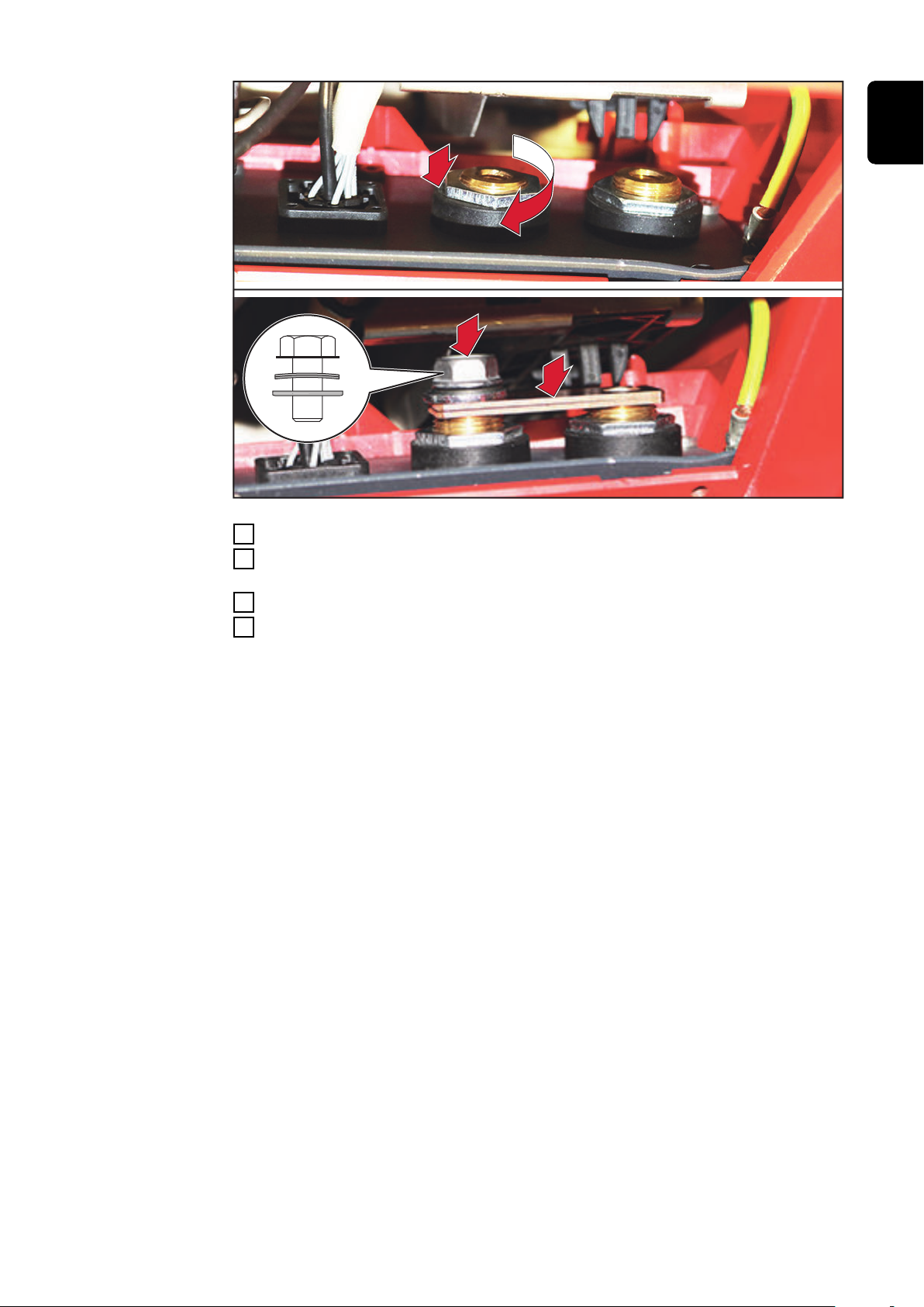
Place the insulating washer on the current socket
5
Fix the current socket with the hexagonal nut
6
size 32 mm, tightening torque = 25 Nm
Position the two busbars on the current socket
7
Screw the busbars to the current socket with the M12 x 20 mm hexagonal
8
bolt + disk spring + washer A13 – do not tighten yet!
Size 19 mm
EN-US
IMPORTANT! The bulge of the disk spring must face the bolt head, the non-
rounded side of the washer must face the disk spring.
15

9
9
1
0
Screw the hexagonal bolt from work step 2 onto the free current socket with
9
star, disk spring, and washer, and tighten
size 19 mm, tightening torque = 15 Nm
Tighten the hexagonal bolt on the 2nd current socket
10
size 19 mm, tightening torque = 15 Nm
Final Tasks
Return the control panel to its original position
1
Use two TX25 screws to secure the control panel to the power source
2
Fit the right side panel to the power source and secure using five TX25
3
screws
16

Screwing the cable onto the second current so-
(2)
(1)
(2)
(2)
(3)
(4)
(5)
(6)
3
1
cket
Screwing the cable onto the second current socket
IMPORTANT! The current socket cover (1) must fit tightly against the connec-
tion cable. If necessary, cut the current socket cover (1) at one of the points marked (2).
EN-US
Cut the current socket cover (1) at one of the points marked (2)
1
Push the current socket cover (1) onto the connection cable
2
Screw the cable lug of the connection cable to the current socket as follows
3
with the supplied fastening material:
M12 x 30 mm hexagonal bolt - disk spring (6) - brass washer (5) - cable lug (4)
- brass washer (3)
size 19 mm, tightening torque = 15 - 35 Nm
17

4
Push the current socket cover over the current socket
4
18

EN-US
19

 Loading...