


Fronius prints on elemental chlorine free paper (ECF) sourced from certified sustainable forests (FSC).
/ Perfect Charging / Perfect Welding / Solar Energy
OPT/i SpeedNet CWF
Installationsanleitung
DE
WIG-Stromquelle
Installation instructions
TIG power source
EN-US
42,0410,2633 001-19112020


Allgemeines
(1)
(2) (3) (4)
DE
Sicherheit
Ein elektrischer Schlag kann tödlich sein.
Vor Öffnen des Gerätes
▶
▶
▶
▶
Fehlerhaft durchgeführte Arbeiten können schwerwiegende Personen- und
Sachschäden verursachen.
▶
▶
Allgemeines Die OPT/i TIG SpeedNet CWF wird an der Stromquellen-Vorderseite montiert.
WARNUNG!
Netzschalter in Stellung - O - schalten
Gerät vom Netz trennen
ein verständliches Warnschild gegen Wiedereinschalten anbringen
mit Hilfe eines geeigneten Messgerätes sicherstellen, dass elektrisch geladene Bau-
teile (z.B. Kondensatoren) entladen sind
WARNUNG!
Nachfolgend beschriebene Tätigkeiten dürfen nur von geschultem Fachpersonal
durchgeführt werden!
Beachten Sie das Kapitel „Sicherheitsvorschriften“ in der Bedienungsanleitung der
Stromquelle und der Systemkomponenten.
Lieferumfang
Die OPT/i TIG SpeedNet CWF und die OPT/i TIG NT601 sind für den Betrieb eines
Drahtvorschubes erforderlich.
(1) 2x Schraube TX20
(2) 3x Kabelbinder
(3) Abdeckung
(4) Kabelbaum
OPT/i TIG SpeedNet CWF
Erforderliche
Werkzeuge
- Torx Schraubendreher TX 25
- Torx Schraubendreher TX 20
- Spitzzange
- Seitenschneider
3
OPT/i TIG SpeedNet CWF bei vorhandener OPT/i
iWave DCiWave AC/DC
5x TX25
7x TX25
1
1
1
2
1
1
1
1
1
2
1
1
1
1
iWave DCiWave AC/DC
5x TX25
7x TX25
1
1
1
1
1
1
1
2
1
1
1
1
1
2
TIG NT601 einbauen
Vorbereitung
Stromquelle ausschalten und vom Netz trennen
1
2
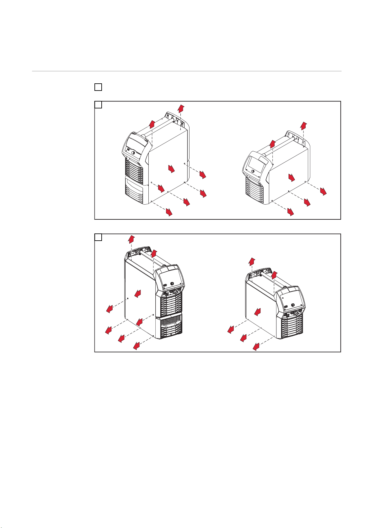
Rechten Seitenteil entfernen
3
Linken Seitenteil entfernen
4
2
2x TX25
1
1
4
2x TX25
2
2
3
1
3x TX25
1
1
1
2
1
2
3
5
DE
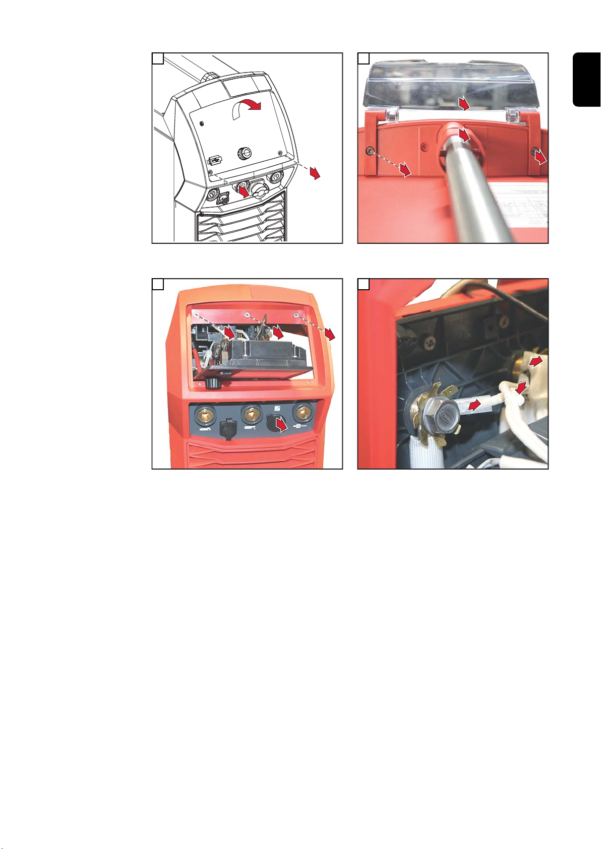
Bedienpanel entfernen
6
3 Schrauben TX25 entfernen;
Blindabdeckung entfernen
Griffspange lösen;
Bedienpanel-Abdeckung entfernen
7
Flachstecker vom linken Buchsenstern abstecken;
Schutzbeschaltung vom mittleren Buchsenstern
abstecken;
Flachstecker vom mittleren Buchsenstern abstecken
5

OPT/i TIG Speed-
1
2
2x TX20
3
3
3x TX25
1
1
1
4
1
1
3
2
1
Net CWF bei vorhandener OPT/i
TIG NT601 einbauen
1
2
Front leicht nach vorne ziehen;
Stecker vom Kabelbaum mit der breiten Ausnehmung
oben von innen nach außen in die Öffnung einsetzen;
Stecker mit 2 Schrauben TX20 fixieren,
Anzugsmoment = 1,5 Nm
3
Flachstecker am linken Buchsenstern anstecken (2x);
Flachstecker am mittleren Buchsenstern anstecken;
Schutzbeschaltung am mittleren Buchsenstern anstecken;
schwarzes Datenkabel am Print SMB500i anstecken
Geräte-Front mit 3 Schrauben TX25 montieren,
Anzugsmoment = 3 Nm
4
2-poliges Kabel vom Kabelbaum mittels Spitzzange
am Print HF500i / X10 anstecken
6

2
1
2
5
2x TX25
1
3
2
2
6
DE
Abschließende
Tätigkeiten
4-poliges Kabel *) vom Kabelbaum am Print NT601 /
X1 anstecken;
Kabelbaum mit Kabelbinder fixieren;
Kabelbinder ablängen
Bedienpanel einsetzen - keine Kabel einklemmen
oder beschädigen!
Bedienpanel mit 2 Schrauben TX25 fixieren,
Anzugsmoment = 3 Nm;
Abdeckung anbringen
*)
HINWEIS!
Ist in der Stromquelle kein Print NT601 vorhanden, bleibt das 4-polige Kabel vom
Kabelbaum frei.
In diesem Fall das 4-polige Kabel mittels Kabelbinder mitfixieren.
▶
Rechten und linken Seitenteil montieren:
1
iWave DC mit je 5 Schrauben TX25
iWave AC/DC mit je 7 Schrauben TX25
Anzugsmoment = 3 Nm
Bedienpanel-Abdeckung mit 2 Schrauben TX25 montieren
2
Anzugsmoment = 3 Nm
Griffspange montieren
3
7

General
(1)
(2) (3) (4)
Safety
An electric shock can be fatal.
Before opening the device
▶
▶
▶
▶
Work performed incorrectly can cause serious injury and damage to property.
▶
▶
General The OPT/i TIG SpeedNet CWF is mounted on the front of the power source.
WARNING!
Set the power switch to - O Unplug the device from grid power
Attach a clear warning sign advising others not to switch the power source back on
Use a suitable measuring instrument to ensure that electrically charged components
(e.g., capacitors) are discharged
WARNING!
Only trained and qualified personnel may carry out the activities described in the following.
Please note the information in the "Safety Rules" chapter in the Operating Instructions for the power source and the system components.
Scope of supply
The OPT/i TIG SpeedNet CWF and the OPT/i TIG NT601 are required to operate a wirefeeder.
(1) 2x TX20 screws
(2) 3x cable ties
(3) Cover
(4) Cable harness
OPT/i TIG SpeedNet CWF
Tools required - Torx screwdriver, TX25
- Torx screwdriver, TX20
- Needle-nosed pliers
- Diagonal cutting pliers
8

OPT/i TIG SpeedNet CWF bei vorhandener OPT/i
iWave DCiWave AC/DC
5x TX25
7x TX25
1
1
1
2
1
1
1
1
1
2
1
1
1
1
iWave DCiWave AC/DC
5x TX25
7x TX25
1
1
1
1
1
1
1
2
1
1
1
1
1
2
TIG NT601 einbauen
Preparation
Switch off the power source and disconnect from the mains
1
2
Remove the right side panel
3
EN-US
Remove left side panel
9

2
2x TX25
1
1
4
2x TX25
2
2
3
1
3x TX25
1
1
1
2
1
2
3
5
Remove control panel
6
Remove the 3 TX25 screws;
Remove the dummy cover
Undo the handle clip;
Remove the control panel cover
7
Disconnect the tab connector from the left star;
Disconnect the protective circuit from the center star;
Disconnect the tab connector from the center star
10

Installing OPT/i
1
2
2x TX20
3
3
3x TX25
1
1
1
4
1
1
3
2
1
TIG SpeedNet
CWF with existing OPT/i TIG
NT601
1
2
EN-US
Pull the front panel slightly forward;
Insert the connector from the cable harness with the
wide recess at the top from the inside out into the
opening;
Secure the connector with 2 TX20 screws,
tightening torque = 1.5 Nm
3
Connect the tab connector to the left star (2x);
Connect the tab connector to the center star;
Connect the protective circuit to the center star;
Connect the black data cable to the PC board
SMB500i
Mount the device front panel using 3 TX25 screws
Tightening torque = 3 Nm
4
Connect the 2-pin plug from the cable harness to the
PC board HF500i / X10 using needle-nosed pliers
11

2
1
2
5
2x TX25
1
3
2
2
6
Final tasks
Connect the 4-pin cable *) from the cable harness to
the PC board NT601 / X1;
Secure cable harness with cable tie;
Cut cable tie to length
Insert the control panel - do not pinch or damage any
cables!
Secure the control panel with 2 TX25 screws,
tightening torque = 3 Nm;
Attach the cover
*)
NOTE!
If there is no PC board NT601 in the power source, the 4-pin cable from the cable
harness remains free.
In this case, secure the 4-pin cable using cable ties.
▶
Mount the right and left side panel:
1
iWave DC with 5 TX25 screws
iWave AC/DC with 7 TX25 screws
Tightening torque = 3 Nm
Fit the control panel cover using 2 TX25 screws
2
Tightening torque = 3 Nm
Install the handle clip
3
12

EN-US
13

14

EN-US
15

FRONIUS INTERNATIONAL GMBH
Froniusstraße 1
A-4643 Pettenbach
AUSTRIA
contact@fronius.com
www.fronius.com
Under www.fronius.com/contact you will find the addresses
of all Fronius Sales & Service Partners and locations.
 Loading...