


Installation
Instructions
OPT/i TIG PowerConnector DC
OPT/i TIG PowerConnector AC
DE
EN-US
Installationsanleitung
Installation instructions
42,0410,2643 003-27012023


Allgemeines
(1) (2) (3) (4)
(5)
(6)(7)
(10) (8)
(9)
DE
Sicherheit
WARNUNG!
Gefahr durch Fehlbedienung und fehlerhaft durchgeführte Arbeiten.
Schwere Personen- und Sachschäden können die Folge sein.
Alle in diesem Dokument beschriebenen Arbeiten und Funktionen dürfen
▶
nur von technisch geschultem Fachpersonal ausgeführt werden.
Dieses Dokument vollständig lesen und verstehen.
▶
Sämtliche Sicherheitsvorschriften und Benutzerdokumentationen dieses
▶
Gerätes und aller Systemkomponenten lesen und verstehen.
WARNUNG!
Gefahr durch elektrischen Strom.
Schwere Personen- und Sachschäden können die Folge sein.
Vor Beginn der Arbeiten alle beteiligten Geräte und Komponenten ausschal-
▶
ten und von Stromnetz trennen.
Alle beteiligten Geräte und Komponenten gegen Wiedereinschalten sichern.
▶
Nach dem Öffnen des Gerätes mit Hilfe eines geeigneten Messgerätes si-
▶
cherstellen, dass elektrisch geladene Bauteile (beispielsweise Kondensatoren) entladen sind.
Lieferumfang
Erforderliche
Werkzeuge
2 Schlitz-Schraubendreher
-
Torx Schraubendreher TX 20, TX 25, TX 30
-
Kreuz-Schraubendreher
-
Sechskantschlüssel SW 32 mm
-
Sechskantschlüssel SW 19 mm
-
Seitenschneider
-
(1) Stromkabel
(2) 3x Kabelbinder
(3) Sechskant-Schraube
(4) Scheibe
(5) Tellerfeder
(6) Sechskant-Mutter
(7) Isolierscheibe
(8) Buchsengehäuse
(9) Abdeckung
(10) Strombuchse
3

Vorbereitung
A
A
B
B
A
2
3
1
2
A
1
3
A
Rippenelement
an der GeräteRückseite entfernen
Position der Verriegelungen am Rippenelement
A ... Position der oberen Verriegelungen am Rippenelement (Geräte-Vorderseite)
B ... Position der unteren Verriegelungen am Rippenelement (Geräte-Vorderseite)
HINWEIS!
Die Positionen der Verriegelungen am Rippenelement an der Geräte-Rückseite
entsprechen denen der Geräte-Vorderseite.
Schraubendreher-Breite: 5 - 6,5 mm
2 Schraubendreher gemäß Abbil-
1
dung in die vorgesehenen Öffnungen an Position A einführen:
Beide Schraubendreher gleichzei-
2
tig nach außen drücken und halten
Beide Schraubendreher nach hin-
3
ten ziehen und die obere Verriegelung lösen
4

B
5
6
4
5
B
4
6
7
2 Schraubendreher gemäß Abbil-
iWave DCiWave AC/DC
5x TX25
7x TX25
1
1
1
2
1
1
1
1
1
2
1
1
1
1
iWave DC
iWave AC/DC
5x TX25
7x TX25
1
1
1
1
1
1
1
2
1
1
1
1
1
2
4
dung in die vorgesehenen Öffnungen an Position B einführen
Beide Schraubendreher gleichzei-
5
tig nach außen drücken und halten
Beide Schraubendreher nach hin-
6
ten ziehen und die untere Veriegelung lösen
Rippenelement entfernen
7
DE
Vorbereitung
Stromquelle ausschalten und vom Netz trennen
1
2
Rechten Seitenteil entfernen
3
Linken Seitenteil entfernen
5

4
4
4
4
4
5
6
4
4
4
8 Schrauben TX25 entfernen
7
6
1
0
9
8
11
12
12
4
Schraube vom Schalterknopf mit-
5
tels Kreuz-Schraubendreher entfernen
Schalterknopf entfernen
6
2 Schrauben TX20 vom Haupt-
7
schalter entfernen;
Netzkabel-Zugentlastung lösen
8
Anschlussplatte herausklappen
9
Anschlussplatte entlang des Netz-
10
kabels nacht unten schieben
Hintere Griffrohr-Spange lösen
11
und nach vor schieben
2 Schrauben TX20 entfernen und
12
Blockklemme abnehmen
6

13
13
13
14
3 Schrauben TX25 entfernen und
15
1
6
15
13
hinteren Rahmen abziehen
Blindabdeckung entfernen
14
2 Schrauben TX25 entfernen
15
Bedienpanel herausklappen und al-
16
le Kabel abstecken
DE
7

OPT/i TIG PowerConnector einbauen
2
1
1
3
4
4
5
OPT/i TIG
PowerConnector
einbauen
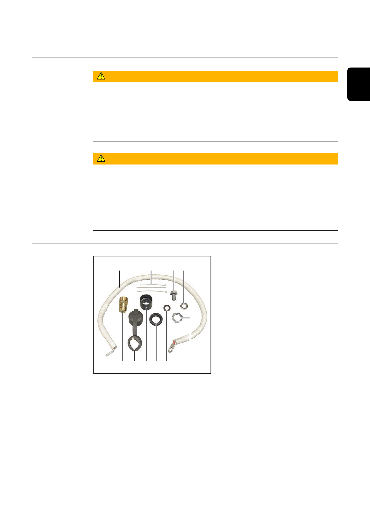
Abdeckung über das Buchsen-
1
gehäuse schieben
Strombuchse in das Buchsen-
2
gehäuse einsetzen
Für den Einbau der Option OPT/i TIG PowerConnector können Gehäusedeckel
und Griffrohr am Gerät verbleiben. In den folgenden 2 Abbildungen ist das Gerät
ohne Gehäusedeckel und Griffrohr abgebildet. Der Einbau erfolgt auf die gleiche
Weise.
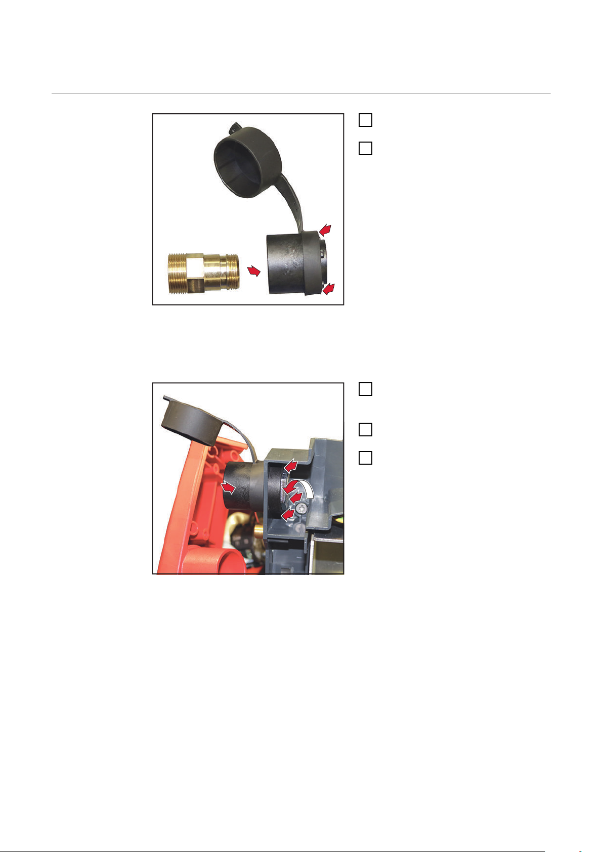
Strombuchse mit Abdeckung und
3
Gehäuse von außen nach innen in
die Öffnung einsetzen
Isolierscheibe innen auf das Buch-
4
sengehäuse aufsetzen
Sechskant-Mutter auf das Gewinde
5
der Strombuchse aufschrauben
und festziehen, SW 32 mm
Anzugsmoment = 10 Nm
WICHTIG! Beim Verlegen des Stromkabels muss der 90°-gebogene Kabelschuh
bei der Geräte-Rückseite sein!
8

90°
6
6
6
6
7
8
Stromkabel gemäß Abbildung verlegen
9
10
10
1
1
1
1
1
1
6
Stromkabel mittels Scheibe, Tellerfeder und Sechskant-Schraube an der
7
Strombuchse anschließen
(Kabelschuh - Scheibe - Tellerfeder - Sechskant-Schraube)
Sechskant-Schraube SW 19 mm festziehen
8
Anzugsmoment = 15 Nm
Stromkabel mit Kabelbinder fixie-
9
ren
DE
Hinteren Rahmen ansetzen
10
Rahmen mit 3 Schrauben TX25 fi-
11
xieren
Anzugsmoment = 3 Nm
9

12
13
12
Blockklemme ansetzen und mit 2
13
14
14
19
19
20
12
Schrauben TX20 fixieren
Anzugsmoment = 1,5 Nm
Hintere Griffrohr-Spange nach hin-
13
ten schieben und fixieren
Rippenelement einsetzen
14
Anschlussplatte einsetzen und mit
15
8 Schrauben TX25 fixieren
Anzugsmoment = 3 Nm
Hauptschalter mit 2 Schrauben
16
TX20 fixieren
Schalterknopf aufsetzen und mit
17
Kreuzschraube fixieren
Netzkabel-Zugentlastung fixieren
18
Stromkabel an iWave DC Stromquellen anschließen
Bei iWave DC Stromquellen wird das Stromkabel an der von vorne gesehenen
rechten Strombuchse angeschlossen.
Sechskant-Schraube SW 19 mm
19
entfernen
HINWEIS!
Die Sechskant-Schraube SW 19
mm kann auch von vorne mit einem TX30 Schraubendreher entfernt werden.
Buchsenstern abnehmen
20
WICHTIG! Das vorhandene Stromka-
bel muss an der Strombuchse verbleiben!
10

21
22
Stromkabel mittels Scheibe, Teller-
1
9
1
9
2
0
2
2
21
21
21
21
feder und Sechskant-Schraube
zum bestehenden Stromkabel dazuschließen
(Kabelschuh vom bestehenden
Stromkabel - Kabelschuh vom neuen Stromkabel - Buchsenstern Scheibe - Tellerfeder - SechskantSchraube)
Sechskant-Schraube SW 19 mm
22
festziehen
Anzugsmoment = 15 Nm
Stromkabel an iWave AC/DC Stromquellen anschließen
Bei iWave AC/DC Stromquellen wird das Stromkabel an der mittleren Strombuchse angeschlossen.
Sechskant-Schraube SW 19 mm
19
entfernen
DE
HINWEIS!
Die Sechskant-Schraube SW 19
mm kann auch von vorne mit einem TX30 Schraubendreher entfernt werden.
Buchsenstern abnehmen
20
WICHTIG! Das vorhandene Stromka-
bel muss an der Strombuchse verbleiben!
Stromkabel mittels Scheibe, Teller-
21
feder und Sechskant-Schraube
zum bestehenden Stromkabel dazuschließen
(Kabelschuh vom bestehenden
Stromkabel - Kabelschuh vom neuen Stromkabel - Buchsenstern Scheibe - Tellerfeder - SechskantSchraube)
Sechskant-Schraube SW 19 mm
22
festziehen
Anzugsmoment = 15 Nm
11

2
3
23
23
2
3
Die am Stromkabel vorhandenen
23
Spreizanker-Kabelbinder in die beiden Öffnungen an der Stromquelle
einsetzen
Abschließende
Tätigkeiten
Rechten und linken Seitenteil montieren:
1
iWave DC mit je 5 Schrauben TX25
iWave AC/DC mit je 7 Schrauben TX25
Anzugsmoment = 3 Nm
WICHTIG! Beim Anstecken der Kabel am Bedienpanel darauf achten, dass
das schwarze Kabel nicht am Anschluss Ethernet angeschlossen wird.
Bedienpanel anschließen und einsetzen
2
Bedienpanel mit 2 Schrauben TX25 montieren
3
Anzugsmoment = 3 Nm
12
General
(1) (2) (3) (4)
(5)
(6)(7)
(10) (8)
(9)
Safety
WARNING!
Danger from incorrect operation and work that is not carried out properly.
This can result in serious personal injury and damage to property.
All the work and functions described in this document must only be carried
▶
out by technically trained and qualified personnel.
Read and understand this document in full.
▶
Read and understand all safety rules and user documentation for this equip-
▶
ment and all system components.
WARNING!
Danger from electrical current.
This can result in serious personal injury and damage to property.
Before starting work, switch off all devices and components involved, and
▶
disconnect them from the grid.
Secure all devices and components involved so they cannot be switched back
▶
on.
After opening the device, use a suitable measuring instrument to check that
▶
electrically charged components (such as capacitors) have been discharged.
EN-US
Scope of supply
Tools required
2 slotted screwdrivers
-
Torx screwdriver TX 20, TX 25, TX 30
-
Philips® screwdriver
-
Allen wrench, WAF 32 mm
-
Allen wrench, WAF 19 mm
-
Diagonal cutting pliers
-
(1) Power cable
(2) 3x cable ties
(3) Hexagonal bolt
(4) Washer
(5) Cup spring
(6) Hexagonal nut
(7) Insulating washer
(8) Socket housing
(9) Cover
(10) Current socket
13

Preparation
A
A
B
B
A
2
3
1
2
A
1
3
A
Removing the fin
element from
the rear of the
device
Position of the locking elements on the fin element
A ... Position of the upper locking elements on the fin element (front of device)
B ... Position of the lower locking elements on the fin element (front of device)
NOTE!
The positions of the locking elements on the fin element at the rear of the device correspond to those on the front.
Screwdriver width: 5 - 6.5 mm
Insert the two screwdrivers into
1
the openings provided at position
A as shown in the illustration:
Push both screwdrivers outwards
2
at the same time and hold them in
place
Pull both screwdrivers backwards
3
and release the upper locking element
14

B
5
6
4
5
B
4
6
7
Insert the two screwdriver into the
iWave DCiWave AC/DC
5x TX25
7x TX25
1
1
1
2
1
1
1
1
1
2
1
1
1
1
iWave DC
iWave AC/DC
5x TX25
7x TX25
1
1
1
1
1
1
1
2
1
1
1
1
1
2
4
openings provided at position B as
shown in the illustration
Push both screwdrivers outwards
5
at the same time and hold them in
place
Pull both screwdrivers backwards
6
and release the lower locking element
Remove fin element
7
EN-US
Preparation
Switch off the power source and disconnect from the grid
1
2
Removing the right side panel
3
Removing the left side panel
15

4
4
4
4
4
5
6
4
4
4
Remove the 8 TX25 screws
7
6
1
0
9
8
11
12
12
4
Remove the screw from the switch
5
knob using the Philips® screwdriver
Remove the switch knob
6
Remove the 2 TX20 screws from
7
the main switch
Loosen the mains cable strain-reli-
8
ef device
Fold out the connection plate
9
Slide the connection plate down
10
along the mains cable
Undo the rear handle tube clasp
11
and push forward
Remove the 2 TX20 screws and ta-
12
ke off the block terminal
16

13
13
13
14
Remove the 3 TX25 screws and
15
1
6
15
13
pull off the rear frame
Remove the dummy cover
14
Remove the 2 TX25 screws
15
Fold out the control panel and dis-
16
connect all cables
EN-US
17
Installing the OPT/i TIG PowerConnector
2
1
1
3
4
4
5
Installing the
OPT/i TIG
PowerConnector
Slide the cover over the socket
1
housing
Insert the current socket into the
2
socket housing
For the installation of the OPT/i TIG PowerConnector option, the housing cover
and handle tube can remain on the device. In the following 2 illustrations, the device is shown without the housing cover and handle tube. The installation is performed in the same way.
Insert the current socket with co-
3
ver and housing into the opening
from the outside inwards
Place the insulating washer on the
4
inside of the socket housing
Screw hexagonal nut onto the
5
thread of the current socket and
tighten, WAF 32 mm
Tightening torque = 10 Nm
18
IMPORTANT! When laying the power cable, the 90° cable lug must be at the rear
of the device!

90°
6
6
6
6
7
8
Lay the power cable according to the illustration
9
10
10
1
1
1
1
1
1
6
Connect the power cable to the current socket using the washer, disc spring,
7
and hexagonal bolt
(cable lug - washer - disc spring - hexagonal bolt)
Tighten the 19 mm hexagonal bolt
8
Tightening torque = 15 Nm
Fix the power cable in place using a
9
cable tie
EN-US
Attach rear frame
10
Secure the frame using 3 TX25
11
screws
Tightening torque = 3 Nm
19

12
13
12
Insert the block terminal and secu-
13
14
14
19
19
20
12
re with 2 TX20 screws
Tightening torque = 1.5 Nm
Push back the rear handle tube
13
clasp and fix it in place
Insert fin element
14
Insert the connection plate and se-
15
cure with 8 TX25 screws
Tightening torque = 3 Nm
Secure the main switch with 2
16
TX20 screws
Put on switch knob and fix it in
17
place with the Philips® screwdriver
Secure the mains cable strain-reli-
18
ef device
Connecting the power cable to iWave DC power sources
For iWave DC power sources, the power cable is connected to the right current
socket as seen from the front.
Remove the 19 mm hexagonal bolt
19
NOTE!
The 19 mm hexagonal bolt can also be removed from the front with
a TX30 screwdriver.
Remove the star
20
IMPORTANT! The existing power cable
must remain connected to the current
socket!
20

21
22
Connect the power cable to the
1
9
1
9
2
0
2
2
21
21
21
21
existing power cable using the washer, disc spring, and hexagonal bolt
(cable lug from the existing power
cable - cable lug from the new
power cable - star - washer - disc
spring - hexagonal bolt)
Tighten the 19 mm hexagonal bolt
22
Tightening torque = 15 Nm
Connecting the power cable to iWave AC/DC power sources
For iWave AC/DC power sources, the power cable is connected to the center current socket.
Remove the 19 mm hexagonal bolt
19
EN-US
NOTE!
The 19 mm hexagonal bolt can also be removed from the front with
a TX30 screwdriver.
Remove the star
20
IMPORTANT! The existing power cable
must remain connected to the current
socket!
Connect the power cable to the
21
existing power cable using the washer, disc spring, and hexagonal bolt
(cable lug from the existing power
cable - cable lug from the new
power cable - star - washer - disc
spring - hexagonal bolt)
Tighten the 19 mm hexagonal bolt
22
Tightening torque = 15 Nm
21

2
3
23
23
2
3
Insert the expansion anchor cable
23
ties on the power cable into the
two openings on the power source
Final tasks
Mount the right and left side panel:
1
iWave DC with 5 TX25 screws each
iWave AC/DC with 7 TX25 screws each
Tightening torque = 3 Nm
IMPORTANT! When connecting the cables to the control panel, make sure
that the black cable is not connected to the Ethernet port.
Connect and insert the control panel
2
Install the control panel using 2 TX25 screws
3
Tightening torque = 3 Nm
22

EN-US
23

 Loading...