


Installation
Instructions
OPT/i TIG NT601
DE
EN-US
Installationsanleitung
Installation instructions
42,0410,2632 004-23022023

Allgemeines
(1)
(2) (3)
(4)
DE
Sicherheit
WARNUNG!
Gefahr durch Fehlbedienung und fehlerhaft durchgeführte Arbeiten.
Schwere Personen- und Sachschäden können die Folge sein.
Alle in diesem Dokument beschriebenen Arbeiten und Funktionen dürfen
▶
nur von technisch geschultem Fachpersonal ausgeführt werden.
Dieses Dokument vollständig lesen und verstehen.
▶
Sämtliche Sicherheitsvorschriften und Benutzerdokumentationen dieses
▶
Gerätes und aller Systemkomponenten lesen und verstehen.
WARNUNG!
Gefahr durch elektrischen Strom.
Schwere Personen- und Sachschäden können die Folge sein.
Vor Beginn der Arbeiten alle beteiligten Geräte und Komponenten ausschal-
▶
ten und von Stromnetz trennen.
Alle beteiligten Geräte und Komponenten gegen Wiedereinschalten sichern.
▶
Nach dem Öffnen des Gerätes mit Hilfe eines geeigneten Messgerätes si-
▶
cherstellen, dass elektrisch geladene Bauteile (beispielsweise Kondensatoren) entladen sind.
Allgemeines Die OPT/i TIG NT601 ist für den Betrieb eines Drahtvorschubes erforderlich.
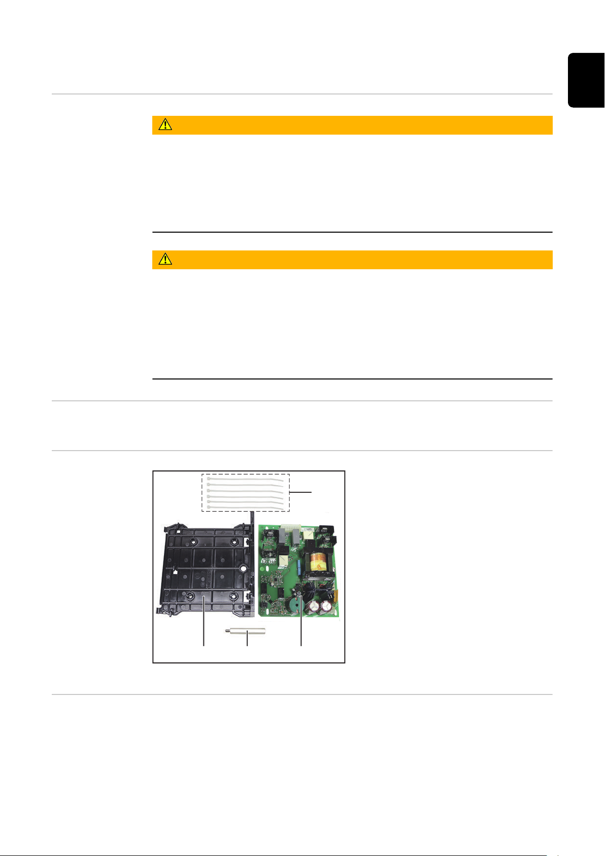
Lieferumfang
Erforderliche
Werkzeuge
OPT/i TIG NT601
Torx Schraubendreher TX 25
-
Steckschlüssel SW 8 mm
-
Seitenschneider
-
(1) Print-Halterung
(2) Messing-Distanz
(3) Print NT601
(4) 6x Kabelbinder
3
OPT/i TIG NT601 einbauen
iWave DCiWave AC/DC
5x TX25
7x TX25
1
1
1
2
1
1
1
1
1
2
1
1
1
1
2
1
2
2
1
1
1
1
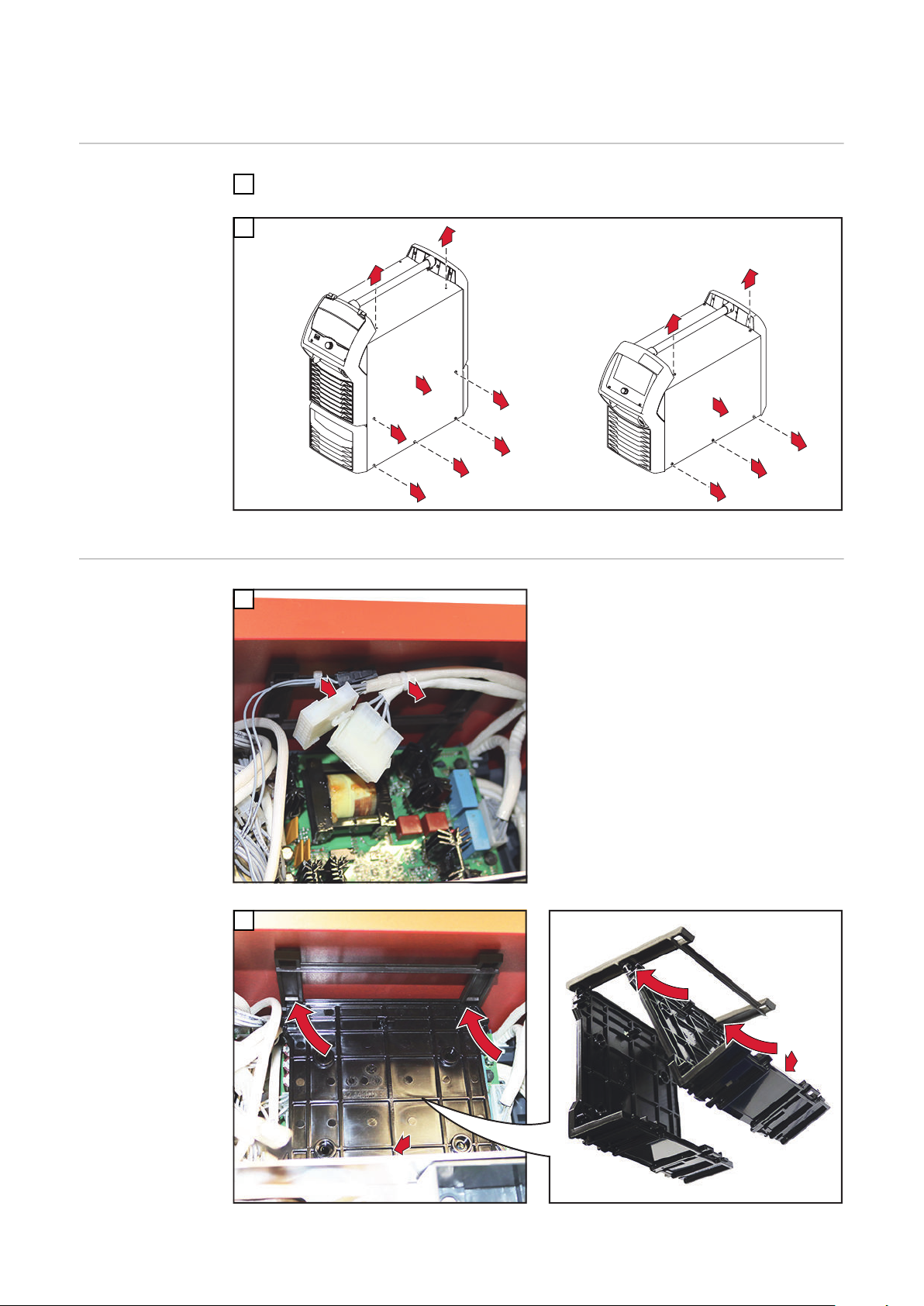
Vorbereitung
OPT/i TIG
NT601 einbauen
Stromquelle ausschalten und vom Netz trennen
1
2
Rechten Seitenteil entfernen
1
2 Kabelbinder entfernen
2
4
Print-Halterung oben einhängen und unten andrücken, bis diese hörbar einrastet

2
3
1
1
2
3
3
1
4
2
5p
4
DE
Abschließende
Tätigkeiten
Print NT601 oben an der Print-Halterung
einhängen;
Print NT601 nach rechts schieben;
Print NT601 unten andrücken
Verbleibendes 4-adriges Kabel (5p) mittels Kabelbinder an der Print-Halte-
5
Print NT601 mittels Messingdistanz M5 x 55 mm
fixieren - SW 8 mm, Anzugsmoment = 1,5 Nm;
vorhandenen 4-poligen Stecker am Print
NT601 / X3
anstecken;
Blindstecker vom 5-adrigen Kabel (5p) entfernen
und 5-adriges Kabel (5p) am Print NT601 / X2
anstecken
rung fixieren
Kabelbinder ablängen
6
Rechten und linken Seitenteil montieren:
1
iWave DC mit 5 Schrauben TX25
iWave AC/DC mit 7 Schrauben TX25
Anzugsmoment = 3 Nm
5

General
(1)
(2) (3)
(4)
Safety
WARNING!
Danger from incorrect operation and work that is not carried out properly.
This can result in serious personal injury and damage to property.
All the work and functions described in this document must only be carried
▶
out by technically trained and qualified personnel.
Read and understand this document in full.
▶
Read and understand all safety rules and user documentation for this equip-
▶
ment and all system components.
WARNING!
Danger from electrical current.
This can result in serious personal injury and damage to property.
Before starting work, switch off all devices and components involved, and
▶
disconnect them from the grid.
Secure all devices and components involved so they cannot be switched back
▶
on.
After opening the device, use a suitable measuring instrument to check that
▶
electrically charged components (such as capacitors) have been discharged.
General The OPT/i TIG NT601 is required to operate a wirefeeder.
Scope of supply
Tools required
OPT/i TIG NT601
Torx screwdriver, TX25
-
Socket wrench size 8 mm
-
Diagonal cutting pliers
-
(1) PC board holder
(2) Brass spacer
(3) PC board NT601
(4) 6x cable ties
6

OPT/i TIG NT601 einbauen
iWave DCiWave AC/DC
5x TX25
7x TX25
1
1
1
2
1
1
1
1
1
2
1
1
1
1
2
1
2
2
1
1
1
1
Preparation
Installing the
OPT/i TIG
NT601
Switch off the power source and disconnect from the grid
1
2
Remove the right side panel
1
EN-US
Remove 2 cable ties
2
Insert the PC board holder at the top and press it down until it audibly clicks into place
7

2
3
1
1
2
3
3
1
4
2
5p
4
Final tasks
Attach PC board NT601 to the PC board holder
at the top;
Push PC board NT601 to the right;
Press PC board NT601 down at the bottom
Fix the remaining 4-core cable (5p) to the PC board holder using a cable tie
5
Trim cable ties
6
Mount the right side panel:
1
Fix the PC board NT601 in place using a M5 x 55
mm brass spacer - WAF 8 mm, tightening torque = 1.5 Nm;
Connect the existing 4-pin plug to the PC board
NT601 / X3
;
Remove the dummy plug from the 5-core cable
(5p) and connect the 5-core cable (5p) to the PC
board NT601 / X2
iWave DC with 5 screws TX25
iWave AC/DC with 7 screws TX25
Tightening torque = 3 Nm
8

EN-US
9

10

EN-US
11

 Loading...