


Installation
Instructions
OPT/i TIG Gas-Durchfluss-Sensor
OPT/i TIG gas flow sensor
DE
EN-US
Installationsanleitung
Installation instructions
42,0410,2638 002-27012023

Allgemeines
(1)
(2)
(3)
(4)
DE
Sicherheit
WARNUNG!
Gefahr durch Fehlbedienung und fehlerhaft durchgeführte Arbeiten.
Schwere Personen- und Sachschäden können die Folge sein.
Alle in diesem Dokument beschriebenen Arbeiten und Funktionen dürfen
▶
nur von technisch geschultem Fachpersonal ausgeführt werden.
Dieses Dokument vollständig lesen und verstehen.
▶
Sämtliche Sicherheitsvorschriften und Benutzerdokumentationen dieses
▶
Gerätes und aller Systemkomponenten lesen und verstehen.
WARNUNG!
Gefahr durch elektrischen Strom.
Schwere Personen- und Sachschäden können die Folge sein.
Vor Beginn der Arbeiten alle beteiligten Geräte und Komponenten ausschal-
▶
ten und von Stromnetz trennen.
Alle beteiligten Geräte und Komponenten gegen Wiedereinschalten sichern.
▶
Nach dem Öffnen des Gerätes mit Hilfe eines geeigneten Messgerätes si-
▶
cherstellen, dass elektrisch geladene Bauteile (beispielsweise Kondensatoren) entladen sind.
Lieferumfang
Erforderliches
Werkzeug
Torx-Schraubendreher TX25
-
Schlauchschere / Messer
-
Seitenschneider
-
Spitzzange
-
(1) Kabel
(2) Gassensor
(3) Zwischenstecker
(4) 2x Kabelbinder
3

Vorbereitung
iWave DCiWave AC/DC
5x TX25
7x TX25
1
1
1
2
1
1
1
1
1
2
1
1
1
1
Vorbereitung
Stromquelle ausschalten und vom Netz trennen
1
2
Rechten Seitenteil entfernen
4
OPT/i TIG Gas-Durchfluss-Sensor einbauen
1
2
3
3
DE
OPT/i TIG Gas-
Durchfluss-Sensor einbauen
Gasschlauch an der Geräte-Vor-
1
derseite abstecken
Kabel am Gassensor anstecken
2
Gasschlauch auf Höhe der Kerbe
3
abschneiden
5

5
4
Gasschlauch gemäß Abbildung am
6
7
9
8
4
Gassensor anstecken
Gassensor in die Ausnehmung ein-
5
setzen und einrasten lassen
Stecker abstecken
6
Stecker vom Sensorkabel vorsich-
7
tig mittels Spitzzange anstecken
Stecker wieder anstecken
8
Sensorkabel mittels Kabelbinder
9
fixieren
6

1
0
11
12
Verbleibendes Gasschlauch-Stück
10
am Gassensor anstecken
Gasschlauch auf Höhe des Winkel-
11
anschlusses ablängen
Gasschlauch am Winkelanschluss
12
anstecken
DE
Abschließende
Tätigkeiten
Rechten und linken Seitenteil montieren:
1
iWave DC mit 5 Schrauben TX25
iWave AC/DC mit 7 Schrauben TX25
Anzugsmoment = 3 Nm
7

General
(1)
(2)
(3)
(4)
Safety
WARNING!
Danger from incorrect operation and work that is not carried out properly.
This can result in serious personal injury and damage to property.
All the work and functions described in this document must only be carried
▶
out by technically trained and qualified personnel.
Read and understand this document in full.
▶
Read and understand all safety rules and user documentation for this equip-
▶
ment and all system components.
WARNING!
Danger from electrical current.
This can result in serious personal injury and damage to property.
Before starting work, switch off all devices and components involved, and
▶
disconnect them from the grid.
Secure all devices and components involved so they cannot be switched back
▶
on.
After opening the device, use a suitable measuring instrument to check that
▶
electrically charged components (such as capacitors) have been discharged.
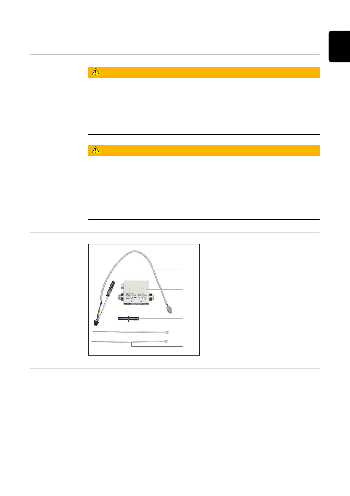
Scope of supply
Required tools
TORX® screwdriver TX25
-
Hose cutters/knife
-
Diagonal cutting pliers
-
Needle-nosed pliers
-
(1) Cable
(2) Gas sensor
(3) Adapter
(4) 2x cable ties
8

Preparation
iWave DCiWave AC/DC
5x TX25
7x TX25
1
1
1
2
1
1
1
1
1
2
1
1
1
1
Preparation
Switch off the power source and disconnect from the grid
1
2
Remove the right side panel
EN-US
9

Installing the OPT/i TIG gas flow sensor
1
2
3
3
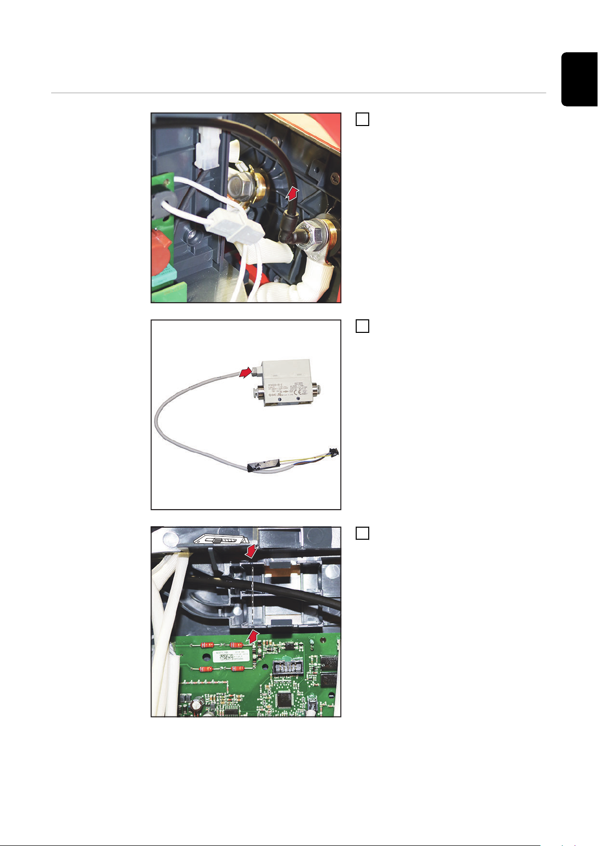
Installing the
OPT/i TIG gas
flow sensor
Disconnect the gas hose from the
1
front of the device
Connect the cable to the gas sen-
2
sor
Cut off the gas hose at the height
3
of the notch
10

5
4
Connect the gas hose to the gas
6
7
9
8
4
sensor as shown in the illustration
Insert the gas sensor into the re-
5
cess and snap it into place
Disconnect the plug
6
Carefully connect the plug of the
7
sensor cable using needle-nosed
pliers
EN-US
Reconnect the plug
8
Fix the sensor cable with a cable
9
tie
11

1
0
11
12
Connect the remaining gas hose
10
piece to the gas sensor
Cut the gas hose to the height of
11
the angle connection
Connect the gas hose to the angle
12
connection
Final tasks
Mount the right side panel:
1
iWave DC with 5 screws TX25
iWave AC/DC with 7 screws TX25
Tightening torque = 3 Nm
12

EN-US
13

14

EN-US
15

 Loading...