


Installation
Instructions
OPT/i TIG 4 Switch SpeedNet
DE
EN-US
Installationsanleitung
Installation instructions
42,0410,2635 003-27012023


Allgemeines
(1)
(2)
(3)
(4)
(5)
(6)
(7)
(8)
DE
Sicherheit
WARNUNG!
Gefahr durch Fehlbedienung und fehlerhaft durchgeführte Arbeiten.
Schwere Personen- und Sachschäden können die Folge sein.
Alle in diesem Dokument beschriebenen Arbeiten und Funktionen dürfen
▶
nur von technisch geschultem Fachpersonal ausgeführt werden.
Dieses Dokument vollständig lesen und verstehen.
▶
Sämtliche Sicherheitsvorschriften und Benutzerdokumentationen dieses
▶
Gerätes und aller Systemkomponenten lesen und verstehen.
WARNUNG!
Gefahr durch elektrischen Strom.
Schwere Personen- und Sachschäden können die Folge sein.
Vor Beginn der Arbeiten alle beteiligten Geräte und Komponenten ausschal-
▶
ten und von Stromnetz trennen.
Alle beteiligten Geräte und Komponenten gegen Wiedereinschalten sichern.
▶
Nach dem Öffnen des Gerätes mit Hilfe eines geeigneten Messgerätes si-
▶
cherstellen, dass elektrisch geladene Bauteile (beispielsweise Kondensatoren) entladen sind.
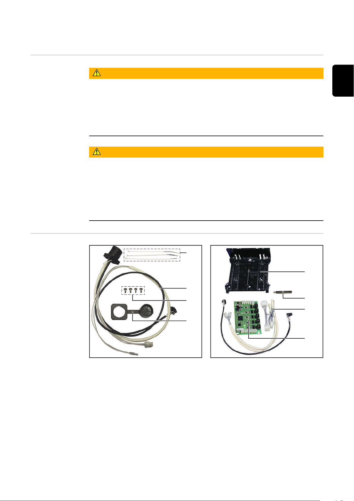
Lieferumfang
(1) 3x Kabelbinder
(2) Kabelbaum
(3) 4x Schraube TX20
(4) Abdeckung
ohne Abbildung:
diese Installationsanleitung
-
Installationsanleitung OPT/i TIG SpeedNet hinten - 42,0410,2634
-
(5) Print-Halterung
(6) Messing-Distanz
(7) Kabelbaum 2
(8) Print SCRAT
3

Erforderliche
Werkzeuge
Torx Schraubendreher TX 25
-
Torx Schraubendreher TX 20
-
Schlitz-Schraubendreher 4 mm
-
Steckschlüssel SW 8 mm
-
Seitenschneider
-
4

OPT/i TIG 4 Switch SpeedNet einbauen
iWave DCiWave AC/DC
5x TX25
7x TX25
1
1
1
2
1
1
1
1
1
2
1
1
1
1
1
3
2
SMB500i
DE
Vorbereitung
Stromquelle ausschalten und vom Netz trennen
1
2
Rechten Seitenteil entfernen
OPT/i TIG SpeedNet hinten gemäß Installationsanleitung 42,0410,2634 an
3
der Stromquelle montieren
WICHTIG! Das Anschließen der OPT/i TIG SpeedNet hinten entfällt:
das 2-polige Kabel NICHT am Print HF500i (X9 oder X10) anstecken
-
das schwarze Datenkabel NICHT am Print SMB500 anstecken
-
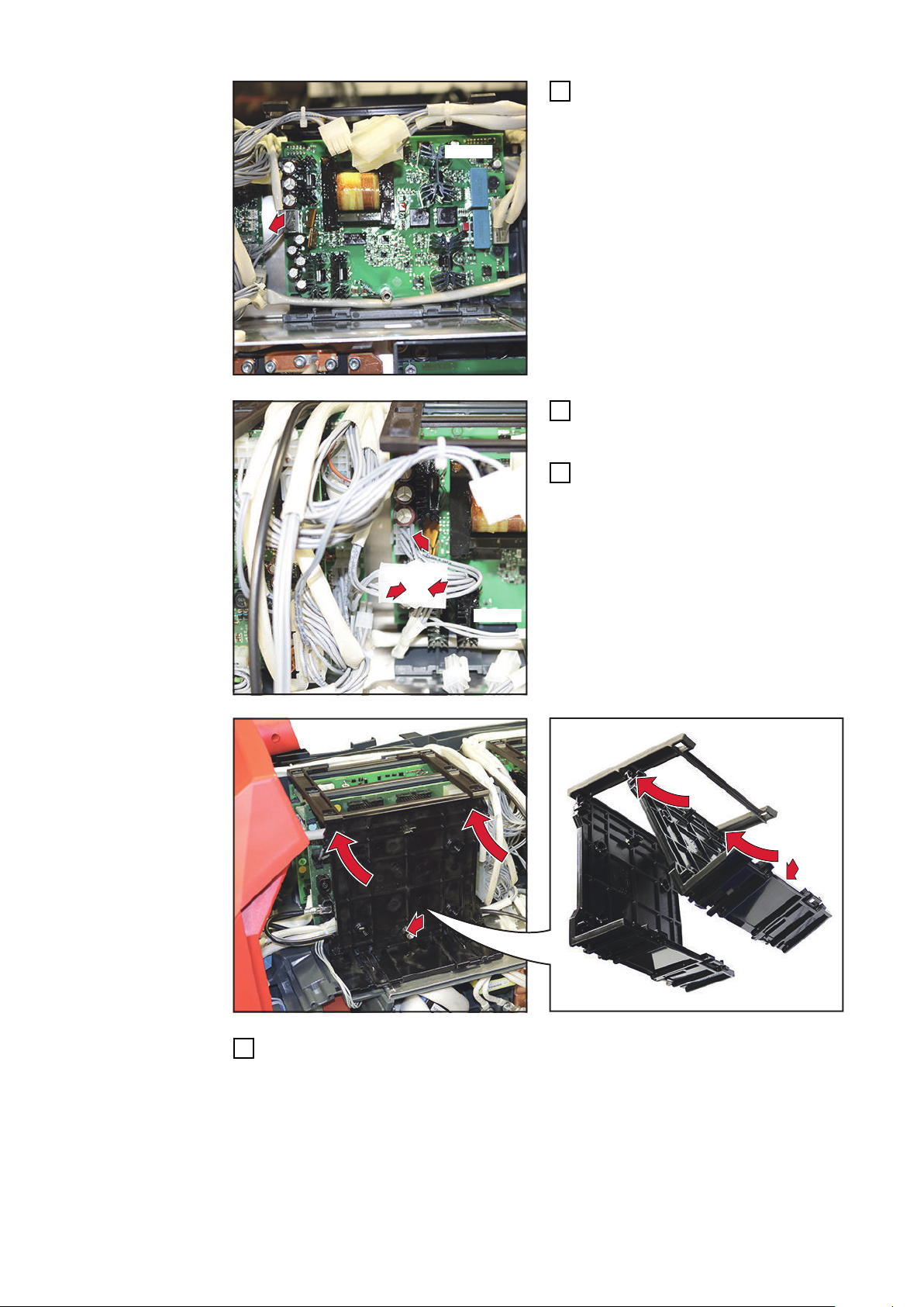
OPT/i TIG 4
Switch SpeedNet einbauen
Schwarzes Datenkabel aus dem
1
Lieferumfang am Print SMB500i
anstecken
Kabel in einer Schlaufe zur Geräte-
2
Rückseite verlegen
Kabel mit Kabelbinder fixieren
3
5

NT242
4
Kabel vom Print NT242 abstecken
NT242
6
5
6
7
7
4
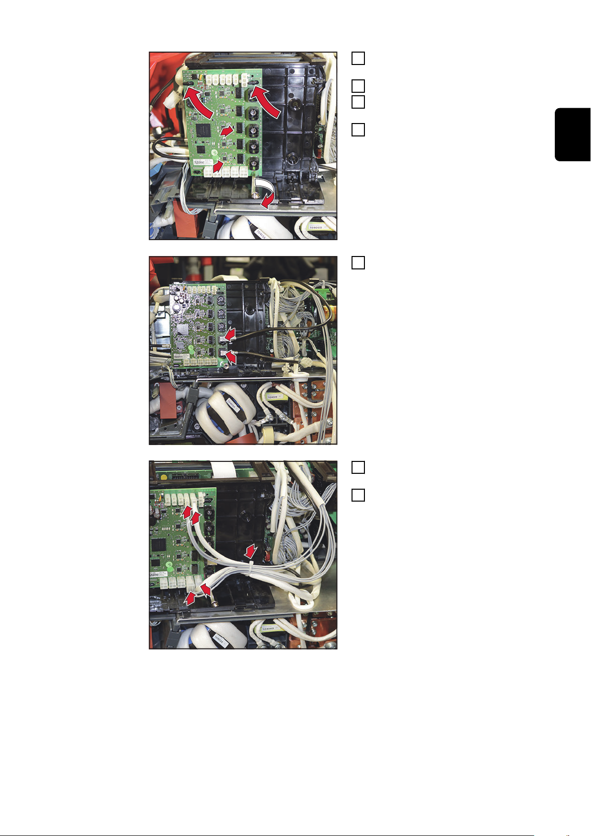
8-poliges Kabel aus dem Lieferum-
5
fang am Print NT242 anstecken
2. Kabelende mit dem zuvor abge-
6
steckten Kabel zusammenstecken
Print-Halterung oben einhängen und unten andrücken, bis diese hörbar ein-
7
rastet
6

9
11
8
8
1
0
Print SCRAT oben an der Print-
12
12
13
1
3
14
1
3
1
3
8
Halterung einhängen;
Print SCRAT nach rechts schieben
9
Print SCRAT unten andrücken
10
Print SCRAT mittels Messingdi-
11
stanz M5 x 55 mm fixieren
SW 8 mm, Anzugsmoment = 1,5
Nm
2 schwarze Datenkabel am Print
12
SCRAT anstecken
DE
Kabel von hinten am Print SCRAT
13
anstecken
Kabel mit Kabelbinder fixieren
14
7

OPT/i TIG 4
11
10
11
Switch SpeedNet bei vorhandenen Option
OPT/i TIG
NT601 einbauen
Sämtliche Kabel vom Print NT601 abstecken
1
Messingdistanz entfernen
2
Print NT601 herausnehmen
3
Print-Halterung entfernen
4
OPT/i TIG 4 Switch SpeedNet einbauen
5
siehe Seite 5
Print-Halterung wieder einsetzen
6
Print NT601 wieder einsetzen
7
Print NT601 mit Messingdistanz fixieren
8
Die zuvor vom Print NT601 abgesteckten Kabel wieder anstecken
9
Freies 4-poliges Kabel am Print
10
NT601 anstecken
2. Kabelende mit dem zur Geräte-
11
Vorderseite führende Kabel zusammenstecken
Abschließende
Tätigkeiten
Rechten und linken Seitenteil montieren:
1
iWave DC mit 5 Schrauben TX25
iWave AC/DC mit 7 Schrauben TX25
Anzugsmoment = 3 Nm
8
General
(1)
(2)
(3)
(4)
(5)
(6)
(7)
(8)
Safety
WARNING!
Danger from incorrect operation and work that is not carried out properly.
This can result in serious personal injury and damage to property.
All the work and functions described in this document must only be carried
▶
out by technically trained and qualified personnel.
Read and understand this document in full.
▶
Read and understand all safety rules and user documentation for this equip-
▶
ment and all system components.
WARNING!
Danger from electrical current.
This can result in serious personal injury and damage to property.
Before starting work, switch off all devices and components involved, and
▶
disconnect them from the grid.
Secure all devices and components involved so they cannot be switched back
▶
on.
After opening the device, use a suitable measuring instrument to check that
▶
electrically charged components (such as capacitors) have been discharged.
EN-US
Scope of supply
(1) 3x cable ties
(2) Cable harness
(3) 4x screws, TX20
(4) Cover
Not shown:
This set of Installation Instructions
-
Installation Instructions for OPT/i TIG SpeedNet rear - 42,0410,2634
-
(5) PC board holder
(6) Brass spacer
(7) Cable harness 2
(8) PC board SCRAT
9

Tools required
Torx screwdriver, TX25
-
Torx screwdriver, TX20
-
Slotted screwdriver, 4 mm
-
Socket wrench, 8 mm
-
Diagonal cutting pliers
-
10

Installing the OPT/i TIG 4 Switch SpeedNet
iWave DCiWave AC/DC
5x TX25
7x TX25
1
1
1
2
1
1
1
1
1
2
1
1
1
1
1
3
2
SMB500i
Preparation
Switch off the power source and disconnect from the grid
1
2
Removing the right side panel
Mount the OPT/i TIG SpeedNet rear to the power source as per the Installa-
3
tion Instructions 42,0410,2634
IMPORTANT! There is no need to connect up the OPT/i TIG SpeedNet rear:
DO NOT connect the 2-pin cable to PC board HF500i (X9 or X10)
-
DO NOT connect the black data cable to PC board SMB500
-
EN-US
Installing the
OPT/i TIG 4
Switch SpeedNet
Connect the black data cable from
1
the scope of supply to PC board
SMB500i
Lay the cable in a loop to the rear
2
of the device
Fix the cable in place using a cable
3
tie
11
NT242
4
Disconnect cable from PC board
NT242
6
5
6
7
7
4
NT242
Connect the 8-pin cable from the
5
scope of supply to PC board
NT242
Connect the second end of the ca-
6
ble to the previously disconnected
cable
Insert the PC board holder at the top and press it down until it audibly clicks
7
into place
12
9
11
8
8
1
0
Insert PC board SCRAT into the
12
12
13
1
3
14
1
3
1
3
8
PC board holder at the top
Slide PC board SCRAT to the right
9
Press PC board SCRAT down at
10
the bottom
Secure PC board SCRAT using the
11
M5 x 55 mm brass spacer
Size 8 mm, tightening torque = 1.5
Nm
Connect 2 black data cables to PC
12
board SCRAT
EN-US
Connect the cable to PC board
13
SCRAT from behind
Fix the cable in place using a cable
14
tie
13

Installing OPT/i
11
10
11
TIG 4 Switch
SpeedNet with
existing OPT/i
TIG NT601 option
Disconnect all cables from PC board NT601
1
Remove brass spacer
2
Remove PC board NT601
3
Remove PC board holder
4
Install OPT/i TIG 4 Switch SpeedNet
5
See page 11
Refit the PC board holder
6
Refit PC board NT601
7
Secure PC board NT601 with the brass spacer
8
Reconnect the cables previously disconnected from PC board NT601
9
Connect free 4-pin cable to PC
10
board NT601
Connect the second cable end to
11
the cable leading to the front of
the device
Final tasks
Mount the right side panel:
1
iWave DC with 5 screws TX25
iWave AC/DC with 7 screws TX25
Tightening torque = 3 Nm
14

EN-US
15

 Loading...