


Fronius prints on elemental chlorine free paper (ECF) sourced from certified sustainable forests (FSC).
/ Perfect Charging / Perfect Welding / Solar Energy
OPT/i SpeedNet Connector iWave230i
Installationsanleitung
DE
Installation instructions
EN-US
42,0410,2391 002-16112021


Allgemeines
DE
Sicherheit
WARNUNG!
Gefahr durch Fehlbedienung und fehlerhaft durchgeführte Arbeiten.
Schwere Personen- und Sachschäden können die Folge sein.
Alle in diesem Dokument beschriebenen Arbeiten und Funktionen dürfen nur von
▶
technisch geschultem Fachpersonal ausgeführt werden.
Dieses Dokument vollständig lesen und verstehen.
▶
Sämtliche Sicherheitsvorschriften und Benutzerdokumentationen dieses Gerätes
▶
und aller Systemkomponenten lesen und verstehen.
WARNUNG!
Gefahr durch elektrischen Strom.
Schwere Personen- und Sachschäden können die Folge sein.
Vor Beginn der Arbeiten alle beteiligten Geräte und Komponenten ausschalten und
▶
von Stromnetz trennen.
Alle beteiligten Geräte und Komponenten gegen Wiedereinschalten sichern.
▶
Nach dem Öffnen des Gerätes mit Hilfe eines geeigneten Messgerätes sicherstel-
▶
len, dass elektrisch geladene Bauteile (beispielsweise Kondensatoren) entladen
sind.
Voraussetzung Für den Betrieb des Einbau-Sets OPT/i SpeedNet Con. iWave230i darf das Einbau-Set
OPT/i Ethernet iWave230i (4,101,063) nicht an der Stromquelle vorhanden sein.
Lieferumfang ohne Abbildung:
- diese Installationsanleitung
Erforderliches
Werkzeug
- Schraubendreher TX 20
- Schraubendreher TX 25
- Seitenschneider
3
OPT/i SpeedNet Connector iWave230i einbauen
(1) (1) (1)
(1)(1)
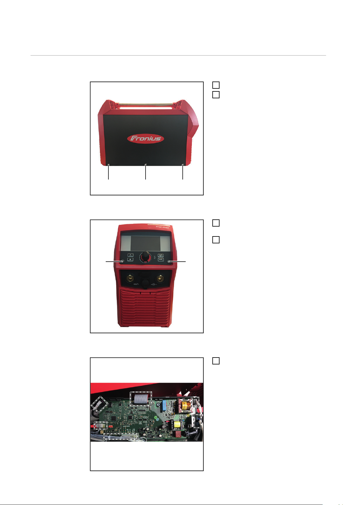
Vorbereitung Linken Seitenteil entfernen
3 Schrauben TX25 (1) entfernen
1
Linken Seitenteil entfernen
2
Bedienpanel demontieren
Print TPC220 ausbauen
2 Schrauben TX25 5x14 mm (1) ent-
1
fernen
Bedienpanel herausklappen
2
Alle Leitungen gemäß Abbildung ab-
1
stecken
4
(1)
(2)
(2)
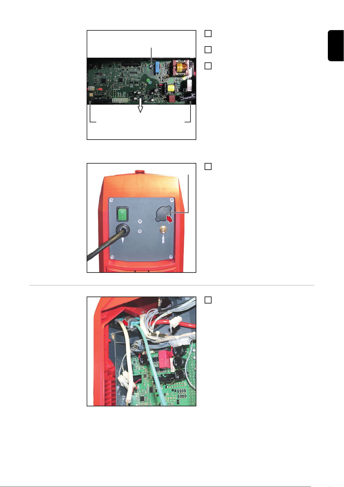
Blindabdeckung entfernen
(1)
1
1
Schraube TX25 5x12 mm (1) entfer-
2
nen
2 Schrauben TX20 4x12 mm (2) ent-
3
fernen
Print TPC220 an der Unterseite nach
4
oben klappen und aus der Print-Halterung entnehmen
Blindabdeckung (1) von innen nach
1
außen entfernen
DE
OPT/i SpeedNet
Connector iWave230i einbauen
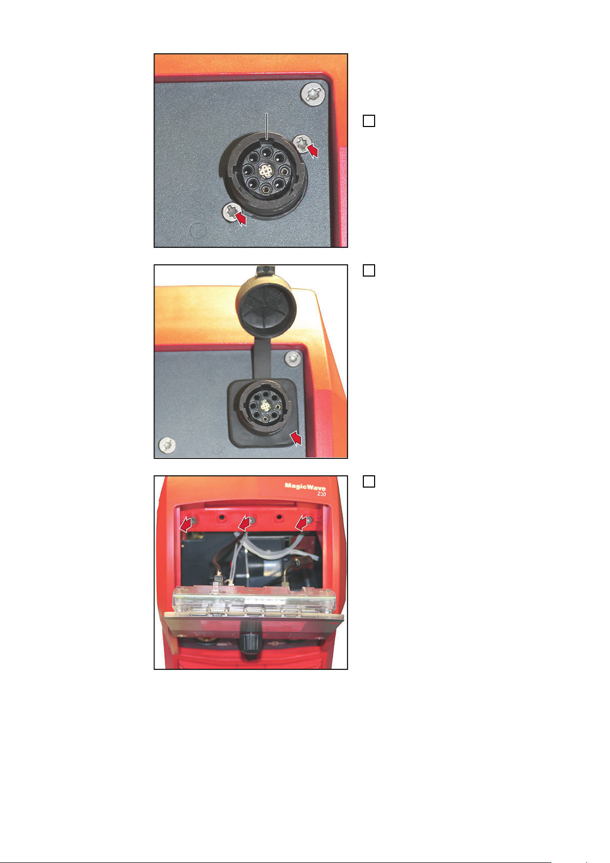
SpeedNet-Anschluss von innen nach
1
außen in die Öffnung einsetzen
5
(1)
2
2
WICHTIG! Beim Einsetzen des SpeedNet-
3
3
3
3
Anschlusses darauf achten, dass die breite Ausnehmung (1) oben ist.
SpeedNet-Anschluss mit 2 Schrauben
2
TX20 fixieren
Anzugsmoment = 1,8 Nm
Abdeckkappe aufsetzen
3
3 Schrauben TX25 entfernen
4
6

5
5
Geräterahmen leicht nach vorne zie-
7
6
7
7
8
8
5
hen und SpeedNet-Kabel von hinten
nach vorne durchfädeln
SpeedNet-Kabel am Bedienpanel an-
6
stecken
Geräterahmen mit 3 Schrauben TX25
7
fixieren
Anzugsmoment = 3 Nm
DE
SpeedNet-Kabel mit 2 Kabelbindern fi-
8
xieren
Kabelbinder ablängen
9
7

10
Kabel vom SpeedNet-Anschluss
X2:2
X2:4
1
1
10
gemäß Kabelaufdruck am 4-poligen
Molexstecker anstecken:
Kabel mit Kabelbinder fixieren
11
Kabelbinder ablängen
12
Print TPC220 einbauen
Print TPC220 gemäß Abbildung an
1
den oberen Halterungen in die PrintHalterung einsetzen
8

(1) (1)
(2)
2 Schrauben TX20 4x12 mm (1) mon-
(3) (4)
7
7
2
tieren
Anzugsmoment = 1,2 Nm
Schraube TX25 5x12 mm (2) montie-
3
ren
Anzugsmoment = 2,1 nm
Alle Leitungen gemäß Abbildung an-
4
stecken.
Flachstecker X1 (3) und Flachstecker
5
X2 (4) anstecken
DE
Abschließende
Tätigkeiten
Nach Einbau des Prints TPC220 auf
6
richtige Kabelverlegung achten:
der Kabelbinder muss gemäß Abbildung über der Kunststoffnase sein!
Bedienpanel mit 2 Schrauben TX25 5x14 mm montieren
1
Anzugsmoment = 1,5 Nm
Linken Seitenteil mit 3 Schrauben TX25 5x12 mm montieren
2
Anzugsmoment = 3 Nm
9

General
Safety
Danger from incorrect operation and work that is not carried out properly.
This can result in serious personal injury and damage to property.
▶
▶
▶
Danger from electrical current.
This can result in serious personal injury and damage to property.
▶
▶
▶
Requirements When operating the installation set OPT/i SpeedNet Con. iWave230i, the installation set
OPT/i Ethernet iWave230i (4,101,063) must not be connected to the power source.
WARNING!
All the work and functions described in this document must only be carried out by
technically trained and qualified personnel.
Read and understand this document in full.
Read and understand all safety rules and user documentation for this equipment
and all system components.
WARNING!
Before starting work, switch off all devices and components involved, and disconnect them from the grid.
Secure all devices and components involved so they cannot be switched back on.
After opening the device, use a suitable measuring instrument to check that electrically charged components (such as capacitors) have been discharged.
Scope of supply not shown:
- this set of Installation Instructions
Required tools - TX 20 screwdriver
- TX 25 screwdriver
- Side cutters
10

Installing OPT/i SpeedNet Connection iWave230i
(1) (1) (1)
(1)(1)
Preparation Remove left side panel
Remove 3 TX25 screws (1)
1
Remove left side panel
2
Remove control panel
EN-US
Remove the TPC220 PC board
Remove 2 TX25 5x14 mm screws (1)
1
Fold out control panel
2
Disconnect all lines as shown
1
11

(1)
(2)
(2)
Remove dummy cover
(1)
1
1
Remove TX25 5x12 mm screws (1)
2
Remove 2 TX20 4x12 mm screws (2)
3
Fold TPC220 PC board on the bottom
4
upward and remove from the PC
board holder
Remove dummy cover (1) from the in-
1
side out
Installing OPT/i
SpeedNet Connection iWave230i
Insert the SpeedNet Connection into
1
the opening from the inside to the outside
12

(1)
2
2
IMPORTANT! IMPORTANT! When inser-
3
3
3
3
ting the SpeedNet Connection, make sure
that the wide recess (1) is at the top.
Secure the SpeedNet Connection
2
using 2 TX20 screws
Tightening torque = 1.8 Nm
Replace cover cap
3
EN-US
Remove 3 TX25 screws
4
13

5
5
Pull the device frame forward slightly
7
6
7
7
8
8
5
and thread the SpeedNet cable
through from the back toward the front
Connect the SpeedNet cable to the
6
control panel
Secure the device frame using 3 TX25
7
screws
Tightening torque = 3 Nm
Secure SpeedNet cable using 2 cable
8
ties
Cut off cable ties
9
14

10
Connect cable from SpeedNet Con-
X2:2
X2:4
1
1
10
nection as per cable label on the 4-pin
Molex plug:
Attach cable using cable tie
11
Cut off cable ties
12
EN-US
Replace the TPC220 PC board
Place the TPC220 PC board in the PC
1
board holder on the upper holders as
shown
15

(1) (1)
(2)
Insert 2 TX20 4x12 mm screws (1)
(3) (4)
7
7
2
Tightening torque = 1.2 Nm
Insert TX25 5x12 mm screw (2)
3
Tightening torque = 2.1 Nm
Connect all lines as shown.
4
Connect flat plug X1 (3) and flat plug
5
X2 (4)
Final tasks
Ensure cables are laid correctly after
6
installing PC board TPC220:
the cable tie must be placed over the
plastic protrusion as shown.
Mount control panel using 2 TX25 5x14 mm screws
1
Tightening torque = 1.5 Nm
Mount left panel using 3 TX25 5x12 mm screws
2
Tightening torque = 3 Nm
16

EN-US
17

18

EN-US
19

Fronius International GmbH
Froniusstraße 1
4643 Pettenbach
Austria
contact@fronius.com
www.fronius.com
Under www.fronius.com/contact you will find the adresses
of all Fronius Sales & Service Partners and locations.
spareparts.fronius.com
SPAREPARTS
ONLINE
 Loading...