


Fronius prints on elemental chlorine free paper (ECF) sourced from certified sustainable forests (FSC).
/ Perfect Charging / Perfect Welding / Solar Energy
OPT/i SB60i Brenner-Ausblasen
(Gas Junction)
OPT/i SB60i gas junction
(Gas Junction)
Installationsanleitung
DEEN-US
Systemerweiterung
Installation Instructions
System extension
42,0410,2602 001-03062020

2

Inhaltsverzeichnis
Allgemeines ............................................................................................................................................... 5
Lieferumfang......................................................................................................................................... 5
Benötigtes Werkzeug............................................................................................................................ 5
Sicherheit.............................................................................................................................................. 5
Vorbereitung .............................................................................................................................................. 7
Vorbereitung ......................................................................................................................................... 7
OPT/i SB60i Brenner-Ausblasen SB 60i R einbauen ................................................................................ 8
OPT/i SB60i Brenner-Ausblasen in SB 60i R einbauen........................................................................ 8
Abschließende Tätigkeiten......................................................................................................................... 13
Abschließende Tätigkeiten.................................................................................................................... 13
DE
3

4
Allgemeines
(1)
(3)
(4)
(5)
(2)
(6)
(7)
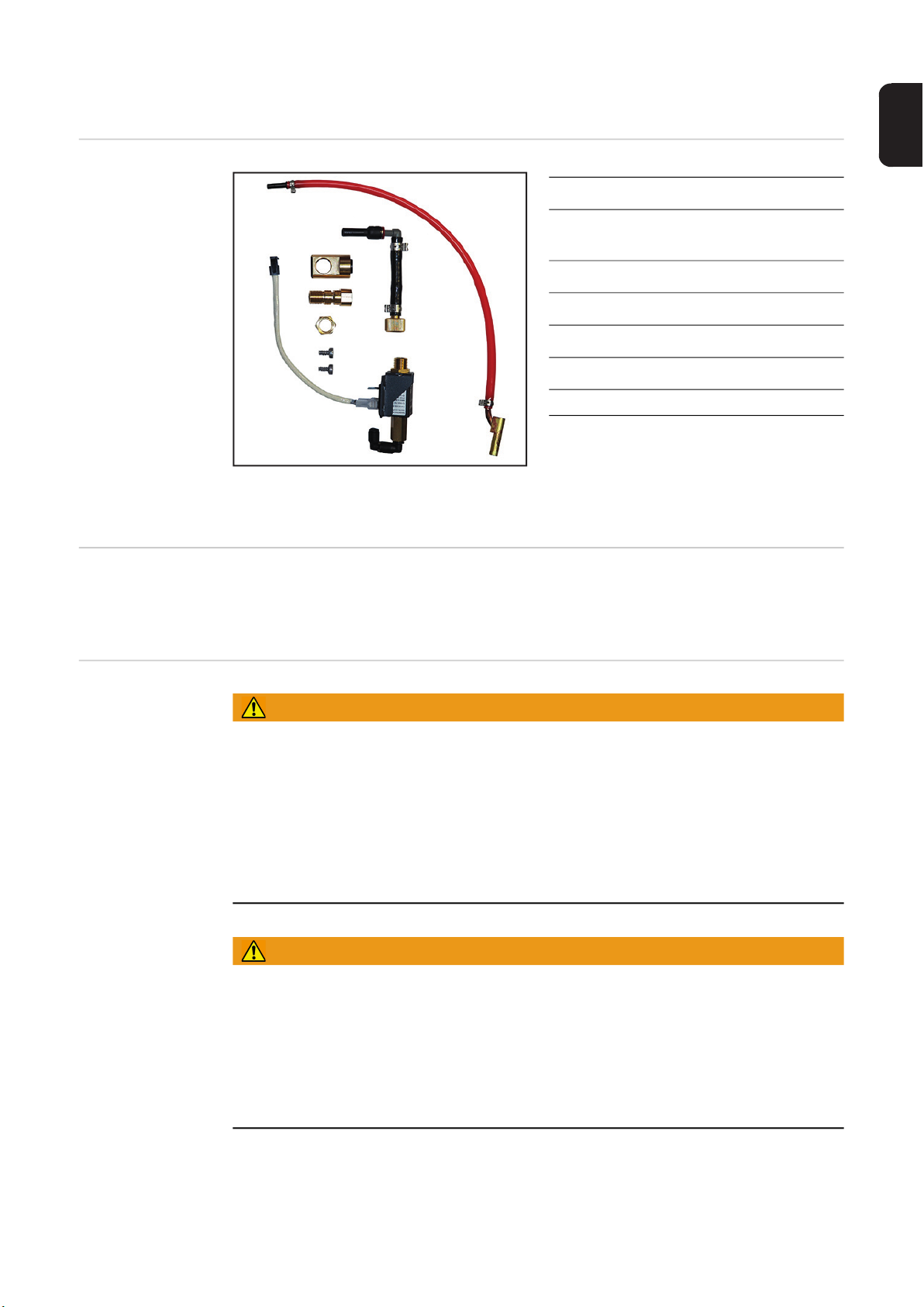
Lieferumfang
DE
(1) Ausblasleitung rot
(2) Gasschlauch mit Steckan-
schluss
(3) Gasverteiler
(4) Hohlschraube
(5) Sechskantmutter SW 17 mm
(6) 2 Schrauben TX25
(7) Magnetventil
Ohne Abbildung:
- 1 Spreizanker
- 1 Kabelbinder
- diese Installationsanleitung
Benötigtes Werkzeug
Sicherheit
- Torx-Schraubendreher TX 25
- Gabelschlüssel SW 16 mm
- Gabelschlüssel SW 17 mm
WARNUNG!
Fehlbedienung und fehlerhaft durchgeführte Arbeiten können schwerwiegende Personen- und Sachschäden verursachen.
► Alle in diesem Dokument beschriebenen Arbeiten und Funktionen dürfen nur von ge-
schultem Fachpersonal ausgeführt werden.
► Alle in diesem Dokument beschriebenen Arbeiten dürfen nur ausgeführt werden, wenn
dieses Dokument vollständig gelesen und verstanden wurde.
► Alle in diesem Dokument beschriebenen Arbeiten dürfen nur ausgeführt werden, wenn
die Bedienungsanleitungen der Systemkomponenten, insbesondere Sicherheitsvorschriften vollständig gelesen und verstanden wurden.
WARNUNG!
Ein elektrischer Schlag kann tödlich sein.
Vor Beginn der Arbeiten:
► Netzschalter der Stromquelle in Stellung - O - schalten
► Stromquelle vom Netz trennen
► sicherstellen, dass die Stromquelle bis zum Abschluss aller Arbeiten vom Netz ge-
trennt bleibt
► Nach dem Öffnen des Gerätes mit Hilfe eines geeigneten Messgerätes sicherstellen,
dass elektrisch geladene Bauteile (z.B. Kondensatoren) entladen sind.
5

VORSICHT!
Verletzungsgefahr durch austretende Drahtelektrode.
Ist ein Abspul-Drahtvorschub im Schweißsystem vorhanden, vor Beginn der Arbeiten:
► Netzschalter des Abspul-Drahtvorschubes in Stellung - O - schalten
► Abspul-Drahtvorschub vom Netz trennen
► sicherstellen, dass der Abspul-Drahtvorschub bis zum Abschluss aller Arbeiten vom
Netz getrennt bleibt
VORSICHT!
Verletzungsgefahr durch heiße Systemkomponenten.
► Vor Beginn der Arbeiten alle heißen Systemkomponenten auf Zimmertemperatur (+25
°C, +77 °F) abkühlen lassen, beispielsweise:
Kühlmittel,
wassergekühlte Systemkomponenten,
Antriebsmotor des Drahtvorschubes
6
Vorbereitung
1
(1)
(2)
(1)
(1)
(1)
(1)
4
5
Vorbereitung Der Einbau wird anhand einer rechten SB 60i R Geräteausführung beschrieben. Der Ein-
bau in eine linke SB 60i R Geräteausführung erfolgt analog dazu.
Sämtliche Verbindungen des Gerätes von allen anderen Systemkomponenten trennen
Gerät vom Roboter abmontieren (4 x Innensechskant-Schraube M6 x 60 mm)
2
Gerät auf einer geeigneten Unterlage mit der durchsichtigen Abdeckung nach unten
3
ablegen
6 Schrauben TX25 (1) lösen
Abdeckung (2) abnehmen
DE
7
OPT/i SB60i Brenner-Ausblasen SB 60i R einbauen
(7)(7)
1
(8)
(9)
2
3
(9)
4
OPT/i SB60i Brenner-Ausblasen in
SB 60i R einbauen
2 Schrauben TX25 (7) am FSC entfernen
FSC (8) zur Seite schwenken
Gasschlauch (9) mit der Schlauchseite
ohne Messingteil in das Gerät einführen
Gasschlauch (9) unterhalb aller Komponenten und Optionen zum Magnetventil verlegen
8

Messingteil (10) des Gasschlauches
(11)
(10)
5
(7)
(7)
6
7
8
(12)
8
bis auf Anschlag in die freie Öffnung
(11) einsetzen
WICHTIG! Beim Einsetzen des FSC darauf achten, dass Kabel und Schläuche nicht eingeklemmt, geknickt, abgeschert oder sonst irgendwie beschädigt werden.
FSC einsetzen
DE
FSC mit 2 Schrauben TX25 (7) fixieren
Anzugsmoment = 3 Nm
Gasschlauch (12) abstecken
9

Kabel (13) vom neuen Magnetventil
(13)
9
9
(14)
9
(15)
10
10
(15)
10
(9)
11
11
mit dem vorhandenen Kabel (14) zusammenstecken
Neues Magnetventil mit 2 Schrauben
TX25 (15) montieren
Anzugsmoment = 3 Nm
Ausblasleitung (9) am neuen Magnetventil anstecken
10

Gasschlauch (12) unter dem neuen
(12)(16)
12
12
13
14
13
15
12
13
14
15
(17)
16
16
16
17
(18)
17
Magnetventil durchführen und wieder
am bestehenden Magnetventil anstecken
Gasschlauch (16) vom bestehenden
Magnetventil abschließen
Kabelbinder entfernen
Gasschlauch (16) mit neuem Spreiz-
anker und Kabelbinder an der unteren
Bohrung fixieren
Hohlschraube (17) aufschrauben und
festziehen
SW 16 mm
DE
Gasverteiler (18) aufschieben
11

Gasschlauch mit Steckanschluss (19)
(19)
18
18
19
18
19
20
(16)
21
(20)
20
21
am neuen Magnetventil anschließen
Gasschlauch mit Steckanschluss (19)
am Gasverteiler anstecken
WICHTIG! Die Gewinde-Freistellung (20)
muss zum Gewinde der Hohlschraube weisen.
Sechskant-Mutter mit der GewindeFreistellung (20) zum Gewinde der
Hohlschraube aufschrauben und festziehen
SW 17 mm
Gasschlauch (16) am Gewinde der
Hohlschraube anschließen
12

Abschließende Tätigkeiten
(1)
(2)
(1)
(1)
(1)
(1)
1
2
DE
Abschließende
Tätigkeiten
Abdeckung (2) einsetzen
Abdeckung mit 6 Schrauben TX25 (1)
festschrauben
Anzugsmoment = 3 Nm
Gerät am Roboter festschrauben (4 x Innensechskant-Schraube M6 x 60 mm)
3
Verbindungen mit den anderen Systemkomponenten herstellen
4
13

14

Table of contents
General ...................................................................................................................................................... 17
Scope of supply .................................................................................................................................... 17
Required tools....................................................................................................................................... 17
Safety.................................................................................................................................................... 17
Preparation ................................................................................................................................................ 19
Preparation ........................................................................................................................................... 19
Installing the OPT/i SB60i torch gas purging in the SB 60i R .................................................................... 20
Installing the OPT/i SB60i torch gas purging in the SB 60i R ............................................................... 20
Finally......................................................................................................................................................... 25
And finally... .......................................................................................................................................... 25
EN-US
15

16

General
(1)
(3)
(4)
(5)
(2)
(6)
(7)
Scope of supply
(1) Gas purging line, red
Required tools - Torx screwdriver TX 25
- Size 16 mm wrench
- Size 17 mm wrench
(2) Gas hose with connection socket
(3) Gas distributor
(4) Banjo bolt
(5) Size 17 mm hexagonal nut
(6) 2 TX25 screws
(7) Solenoid valve
Not pictured:
- 1 expansion anchor
- 1 cable tie
- This set of Installation Instructions
EN-US
Safety
WARNING!
Incorrect operation and incorrectly performed work can cause serious injury and
property damage.
► All the work and functions described in this document must only be carried out by
trained and qualified personnel.
► All work described in this document must only be performed once you have read and
understood this document in full.
► Do not perform the work described in this document until you have thoroughly read and
understood all the Operating Instructions for the system components, especially the
safety rules.
WARNING!
An electric shock can be fatal.
Before beginning work:
► Switch the power switch on the power source to - O ► Disconnect the power source from the grid
► Ensure that the power source remains disconnected from the grid until all work is com-
plete
► After opening the device, use a suitable measuring instrument to ensure that electrical-
ly charged components (e.g., capacitors) are discharged.
17

CAUTION!
Risk of injury from emerging wire electrode.
If there is an unwinding wirefeeder present in the welding system, before starting work:
► Switch the power switch on the unwinding wirefeeder to - O ► Disconnect the unwinding wirefeeder from the mains
► Ensure that the unwinding wirefeeder remains disconnected from the mains until all
work is complete
CAUTION!
Risk of injury from hot system components.
► Before starting work, allow all hot system components to cool to room temperature
(+25 °C, +77 °F), for example:
Coolant,
water-cooled system components,
wirefeeder drive motor
18

Preparation
1
(1)
(2)
(1)
(1)
(1)
(1)
4
5
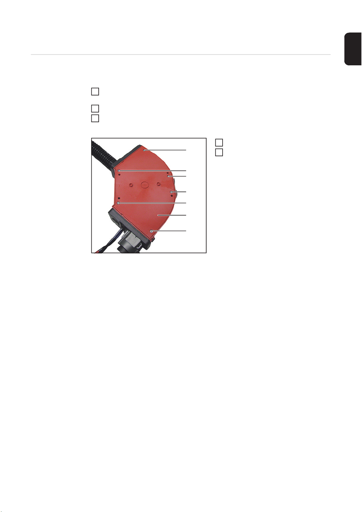
Preparation The installation is described with reference to a right-hand SB 60i R version of the appli-
ance. The installation in a left-hand SB 60i R version of the appliance is the same.
Disconnect the device from all other system components
Remove the device from the robot (4 x Allen screw M6 x 60 mm)
2
Place the device on a suitable surface with the transparent cover facing down
3
Loosen the 6 TX25 screws (1)
Remove cover (2)
EN-US
19

Installing the OPT/i SB60i torch gas purging in the
(7)(7)
1
(8)
(9)
2
3
(9)
4
SB 60i R
Installing the
OPT/i SB60i torch
gas purging in the
SB 60i R
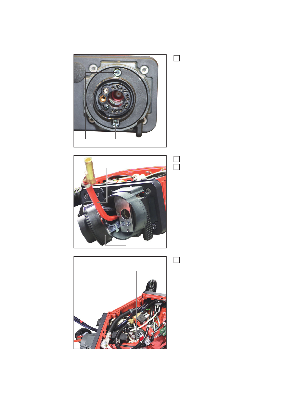
Remove 2 TX25 screws (7) on the FSC
Swivel the FSC (8) to the side
Insert the gas hose (9) into the device
with the hose side without brass section
Route the gas hose (9) underneath all
components and options to the solenoid valve
20
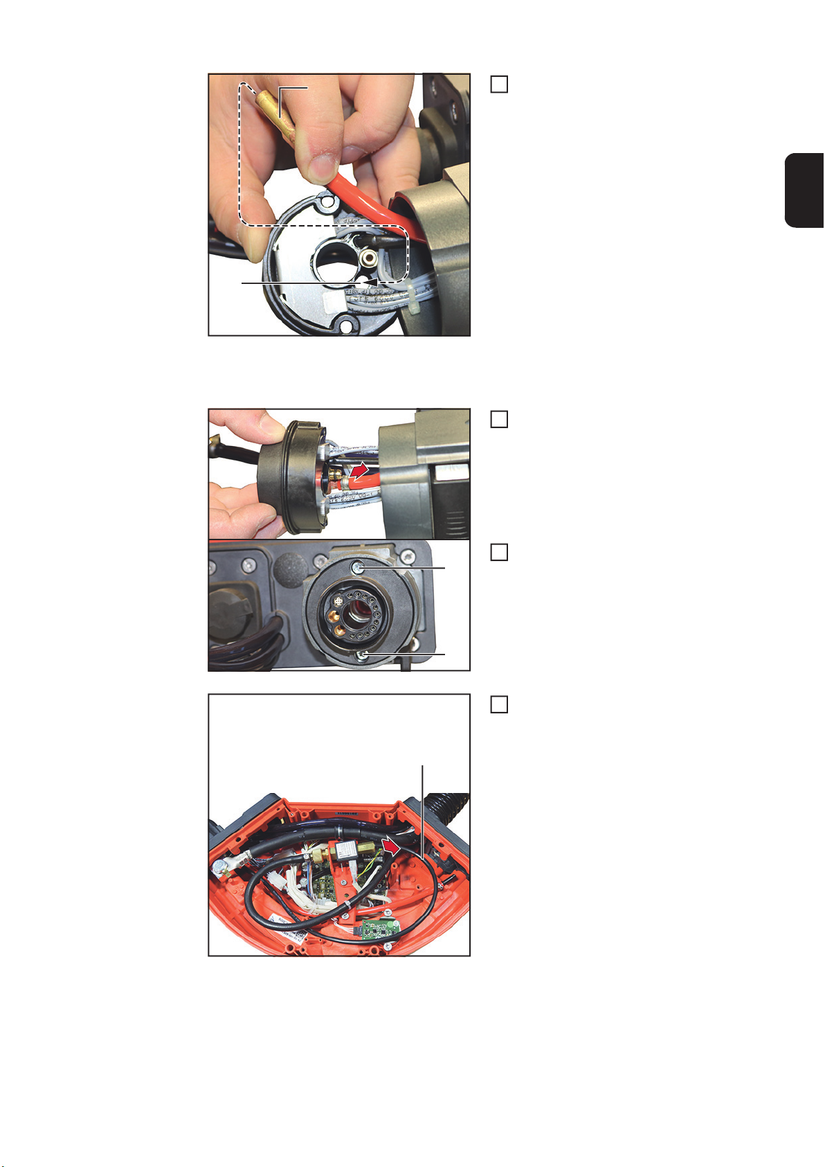
Insert the brass section (10) of the gas
(11)
(10)
5
(7)
(7)
6
7
8
(12)
8
hose into the free opening (11) as far
as it will go
IMPORTANT! When inserting the FSC, ensure that the cables and hoses are not pinched,
kinked, cut, or otherwise damaged.
Inserting the FSC
EN-US
Secure the FSC using 2 TX25 screws
(7)
Tightening torque = 3 Nm
Disconnect the gas hose (12)
21

Connect the cable (13) from the new
(13)
9
9
(14)
9
(15)
10
10
(15)
10
(9)
11
11
solenoid valve to the existing cable
(14)
Fit the new solenoid valve using 2
TX25 screws(15)
Tightening torque = 3 Nm
Connect the gas purging line (9) to the
new solenoid valve
22

Run the gas hose (12) under the new
(12)(16)
12
12
13
14
13
15
12
13
14
15
(17)
16
16
16
17
(18)
17
solenoid valve and reconnect it to the
existing solenoid valve
Disconnect the gas hose (16) from the
existing solenoid valve
Remove cable ties
Secure the gas hose (16) to the bottom
hole with a new expansion anchor and
cable ties
Screw on the banjo bolt (17) and tighten
Size16 mm
EN-US
Push on the gas distributor (18)
23

Connect the gas hose with connection
(19)
18
18
19
18
19
20
(16)
21
(20)
20
21
socket (19) to the new solenoid valve
Connect the gas hose with connection
socket (19) to the gas distributor
IMPORTANT! The thread undercut (20)
must face the thread of the banjo bolt.
Screw on the hexagonal nut with the
thread undercut (20) for the thread of
the banjo bolt and tighten
Size 17 mm
Connect the gas hose (16) to the
thread of the banjo bolt
24

Finally...
(1)
(2)
(1)
(1)
(1)
(1)
1
2
And finally...
Fit the cover (2)
Secure the cover with six TX25 screws
(1)
Tightening torque = 3 Nm
Screw the device to the robot (4 x Allen screws M6 x 60 mm)
3
Establish connections to the other system components
4
EN-US
25

26

EN-US
27

FRONIUS INTERNATIONAL GMBH
Froniusstraße 1
A-4643 Pettenbach
AUSTRIA
contact@fronius.com
www.fronius.com
Under www.fronius.com/contact you will find the addresses
of all Fronius Sales & Service Partners and locations.
 Loading...