


/ Perfect Charging / Perfect Welding / Solar Energy
OPT/i RI Safety Stop out
Installationsanleitung
DEEN-US
Systemerweiterung
Installation Instructions
System extension
42,0410,0131 002-07052018

2

Lieferumfang und erforderliches Werkzeug
DE
Lieferumfang
Erforderliches
Werkzeug
ohne Abbildung:
- 2 Kabelbinder
- diese Installationsanleitung
- Schaltplan
- Schraubendreher TX 20
- Schraubendreher TX 25
- Seitenschneider
3

OPT/i RI Safety Stop out einbauen
Sicherheit
WARNUNG! Fehlbedienung und fehlerhaft durchgeführte Arbeiten können
schwerwiegende Personen- und Sachschäden verursachen.
Alle in diesem Dokument beschriebenen Arbeiten und Funktionen dürfen nur von
geschultem Fachpersonal ausgeführt werden, wenn folgende Dokumente vollständig gelesen und verstanden wurden:
- dieses Dokument
- sämtliche Bedienungsanleitungen der Systemkomponenten, insbesondere
Sicherheitsvorschriften
WARNUNG! Ein elektrischer Schlag kann tödlich sein. Vor Beginn der Arbeiten
alle beteiligten Geräte und Komponenten
- ausschalten
- vom Stromnetz trennen
- gegen Wiedereinschalten sichern.
Nach dem Öffnen des Gerätes mit Hilfe eines geeigneten Messgerätes sicherstellen, dass elektrisch geladene Bauteile (z.B. Kondensatoren) entladen sind.
WARNUNG! Unzureichende Schutzleiter-Verbindung kann schwerwiegende
Personen- und Sachschäden verursachen. Die Gehäuse-Schrauben stellen eine
geeignete Schutzleiter-Verbindung für die Erdung des Gehäuses dar und dürfen
keinesfalls durch andere Schrauben ohne zuverlässige Schutzleiter-Verbindung
ersetzt werden.
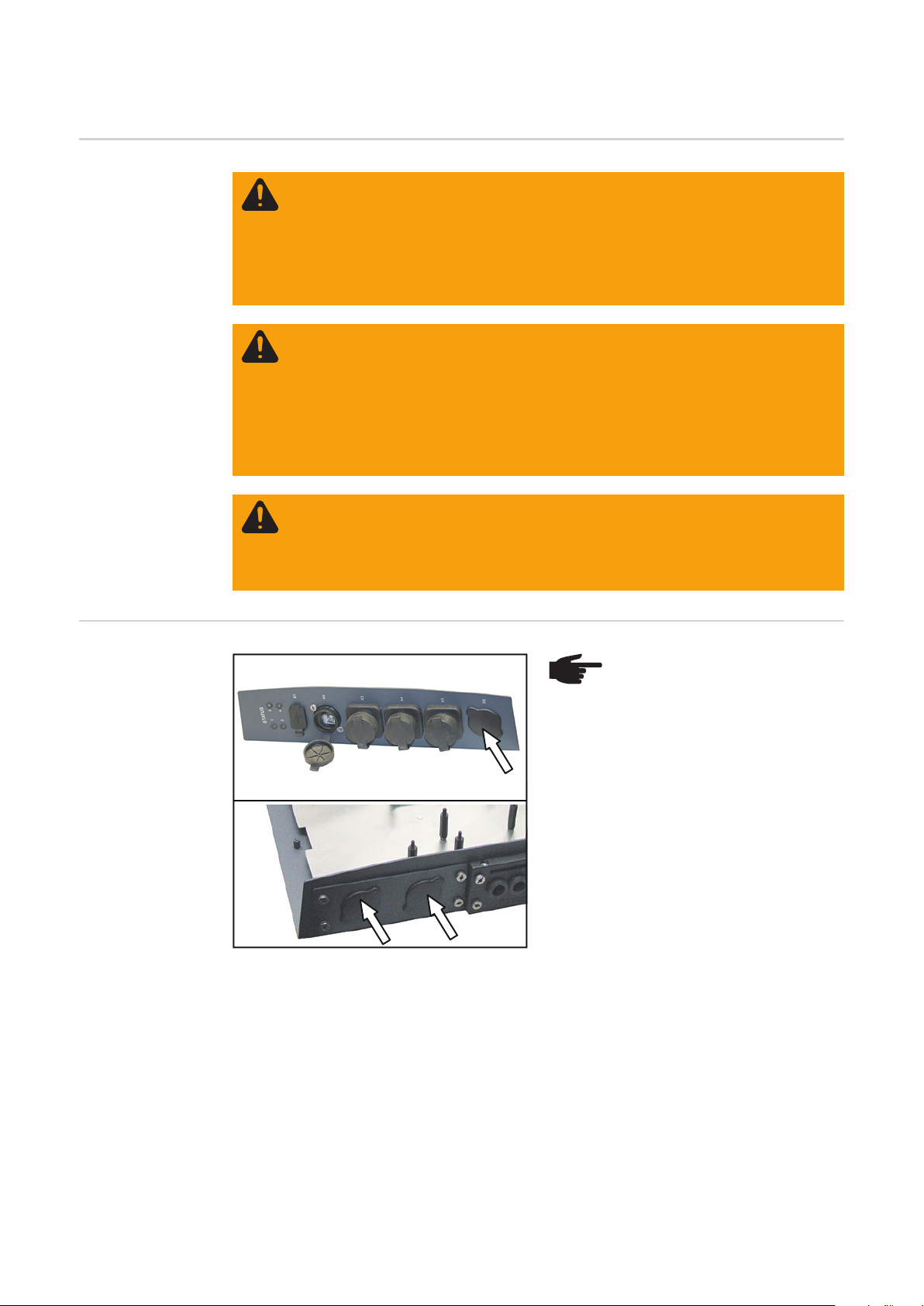
Mögliche Positionen für die Montage
HINWEIS! Die Option OPT/i RI
Safety Stop out kann an folgenden
freien Position mit einer runden
Blindabdeckung montiert werden:
- an der Interface-Vorderseite
bei Anschluss X6
- an der Interface-Rückseite an
den beiden unteren Anschlüssen
In dieser Anleitung wird die Montage an der
Rückseite behandelt.
Die Montage an der Vorderseite erfolgt
analog dazu.
4

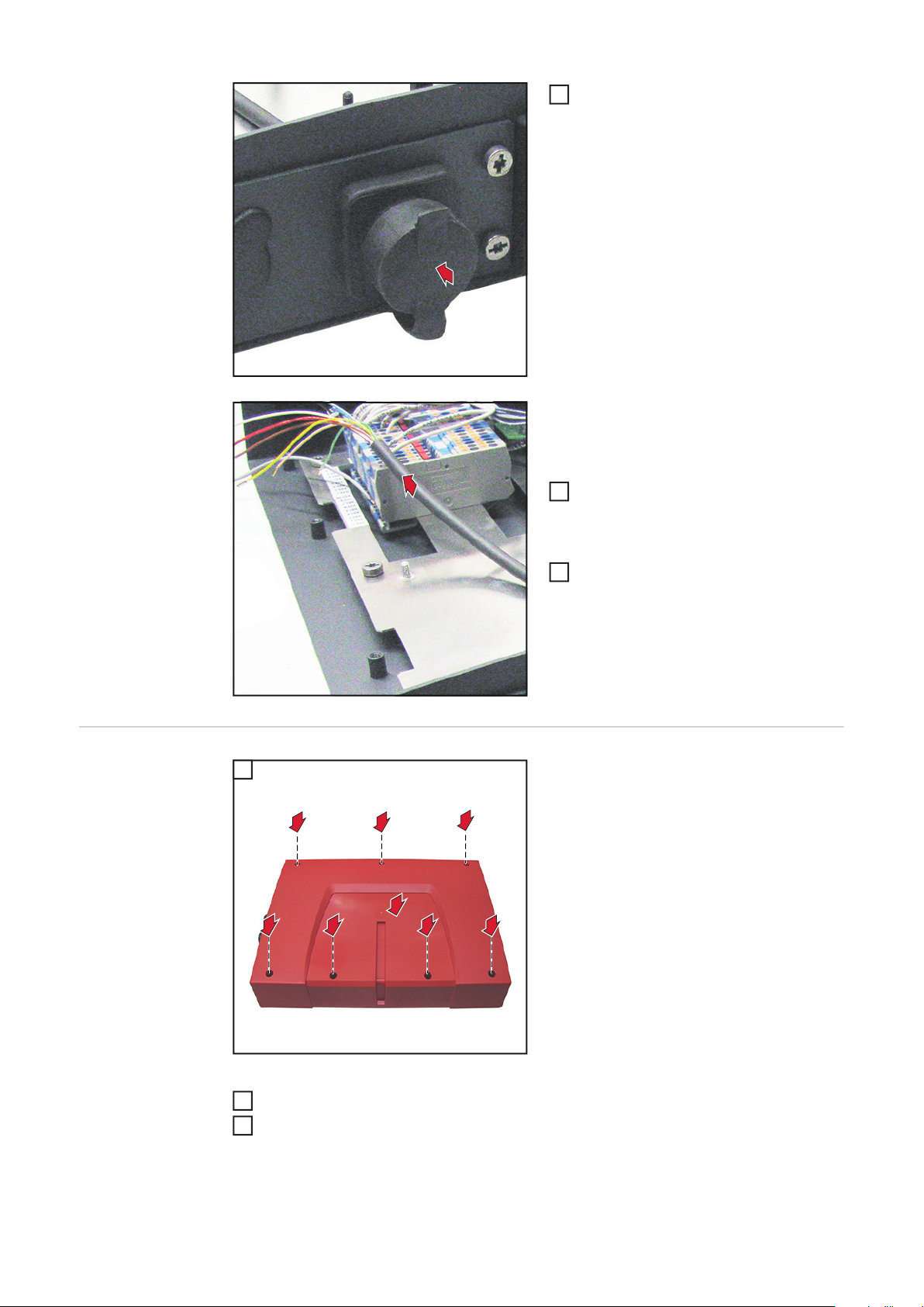
WICHTIG! Der Kabelbaum darf nicht über
den Print Rob Pro verlegt werden!
DE
Vorbereitung Sämtliche Verbindungen des Interfaces von allen anderen Systemkomponenten tren-
1
nen
Interface auf einer geeigneten Unterlage ablegen
2
1 2
3
4
7 x TX25
OPT/i RI Safety
Stop out einbauen
1
1
1
1
2
1
1
1
1
WICHTIG! Beim Einsetzen des Kabels darauf achten, dass die breite Rechteck-Ausnehmung oben ist.
Kabel von innen nach außen in die Öff-
1
1
nung einsetzen
Anschluss mit 2 Schrauben TX20 fixie-
2
ren
2
2
2 x TX20
5

Abdeckkappe aufsetzen
3
3
Die Kabel mit dem grünen Stecker werden
für die Standard-Ausführung des Interfaces
nicht benötigt.
Abschließende
Tätigkeiten
5
Kabel mit dem grünen Stecker in einer
4
Schleife zum Kabelbaum verlegen und
mit 2 Kabelbindern fixieren
Einzelkabel gemäß Kabelfarbe und
5
Schaltplan an den Anschlussklemmen
anschließen
1
1
7 x TX25
2
2
2
2
1
2
2
2
Interface in seine Ausgangsposition bringen
2
Verbindungen des Interfaces mit anderen Systemkomponenten wieder herstellen
3
WICHTIG! Für den Anschluss der OPT/i RI Safety Stop out ausschließlich das 1,5 m Kabel
aus dem Lieferumfang verwenden!
6

Scope of Supply and Tools Required
Scope of Supply
Required tools - TX 20 screwdriver
- TX 25 screwdriver
- Side cutters
Not pictured:
- 2 cable ties
- these Installation Instructions
- Circuit Diagram
EN-US
7
Installing OPT/i RI Safety Stop Out
Safety
WARNING! Incorrect operation and incorrectly performed work can cause seri-
ous injury and damage to property.
All tasks and functions described in this document must only be carried out by
trained specialist personnel once they have read and understood the following
documents in full:
- this document
- all Operating Instructions for system components, especially the safety rules.
WARNING! An electric shock can be fatal. Before beginning the work, all devices
and components must be:
- switched off
- disconnected from the grid
- prevented from being switched back on.
After opening the device, use a suitable measuring tool to ensure that electrically
charged components (e.g. capacitors) are discharged.
WARNING! An inadequate grounding conductor connection can cause serious
injuries to persons and damage to (or loss of) property. The housing screws provide a suitable grounding conductor connection for the housing ground and
should not be replaced under any circumstances by other screws that do not provide a proper grounding conductor connection.
Possible installation positions
NOTE! The OPT/i RI Safety Stop
out option can be installed in the
next free position with a round
dummy cover:
- on the front of the interface at
connection X6
- on the back of the interface at
the two lower connections
These instructions deal with the installation
on the back.
Installation on the front is carried out in the
same way.
8

IMPORTANT! The cable harness must not
be laid over the Rob Pro PCB.
EN-US
Preparation Disconnect all interface connections from all other system components
1
Set the interface aside on a suitable surface
2
2 3
3
4
7 x TX25
Installing OPT/i RI
Safety Stop Out
1
1
1
1
2
1
1
1
1
IMPORTANT! When inserting the cable,
ensure that the wide rectangular opening is
at the top.
Insert cable into the opening from the
1
1
inside.
Fix the connection socket using two
2
TX20 screws.
2
2
2 x TX20
9
Attach cover cap.
3
3
The cables with the green plug are not required for the standard version of the interface.
Final Tasks
5
Route the cables with the green plug to
4
the cable in a loop and fix it using two
cable ties.
Connect the individual cables to the
5
terminals according to the cable color
and the Circuit Diagram.
1
1
7 x TX25
2
2
2
2
1
2
2
2
10
Move the interface to its initial position
2
Re-establish connections between the interface and other system components
3
IMPORTANT! When connecting the OPT/i RI Safety Stop out, only use the 1.5 m cable
included in the scope of supply.

EN-US
11

FRONIUS INTERNATIONAL GMBH
Froniusplatz 1, A-4600 Wels, Austria
Tel: +43 (0)7242 241-0, Fax: +43 (0)7242 241-3940
E-Mail: sales@fronius.com
www.fronius.com
www.fronius.com/addresses
Under http://www.fronius.com/addresses you will find all addresses
of our Sales & service partners and Locations
 Loading...