


Fronius prints on elemental chlorine free paper (ECF) sourced from certified sustainable forests (FSC).
/ Perfect Charging / Perfect Welding / Solar Energy
OPT/i RI REL INT 8I/8O 17P AMP
Installationsanleitung
DEEN
Systemerweiterung
Installations instructions
System extension
42,0410,2326 001-28032017

2

Lieferumfang und benötigtes Werkzeug
Lieferumfang
DE
8x
1x
2x
1x
4x
M4 x 30 mm
4x
M4 x 10 mm
Benötigtes Werkzeug
Ohne Abbildung:
- Schaltplan
- diese Installationsanleitung
- Torx-Schraubendreher TX 25
- Drehmoment-Schlüssel
- Steckschlüssel SW 8 mm
- Kreuz-Schraubendreher PH2
3

OPT/i RI REL INT 8I/8O 17P AMP einbauen
Sicherheit
WARNUNG! Fehlbedienung und fehlerhaft durchgeführte Arbeiten können
schwerwiegende Personen- und Sachschäden verursachen.
Alle in diesem Dokument beschriebenen Arbeiten und Funktionen dürfen nur von
geschultem Fachpersonal ausgeführt werden, wenn folgende Dokumente vollständig gelesen und verstanden wurden:
- dieses Dokument
- sämtliche Bedienungsanleitungen der Systemkomponenten, insbesondere
Sicherheitsvorschriften
WARNUNG! Ein elektrischer Schlag kann tödlich sein. Vor Beginn der Arbeiten
alle beteiligten Geräte und Komponenten
- ausschalten
- vom Stromnetz trennen
- gegen Wiedereinschalten sichern.
Nach dem Öffnen des Gerätes mit Hilfe eines geeigneten Messgerätes sicherstellen, dass elektrisch geladene Bauteile (z.B. Kondensatoren) entladen sind.
WARNUNG! Unzureichende Schutzleiter-Verbindung kann schwerwiegende
Personen- und Sachschäden verursachen. Die Gehäuse-Schrauben stellen eine
geeignete Schutzleiter-Verbindung für die Erdung des Gehäuses dar und dürfen
keinesfalls durch andere Schrauben ohne zuverlässige Schutzleiter-Verbindung
ersetzt werden.
Vorbereitung Sämtliche Verbindungen des Interfaces von allen anderen Systemkomponenten tren-
OPT/i RI REL INT
8I/8O 17P AMP
einbauen
1
nen
Interface auf einer geeigneten Unterlage ablegen
2
(1)(1) (2)(1)
(1)(1)(1)(1)
7 Schrauben (1) lösen
1
- TX 25
Abdeckung (2) entfernen
2
4

(3)
(4)
(5)
(2) (2) (2) (2)
4 Kunststoff-Distanzen M4 x 10 mm (2)
3
festschrauben
- SW 8 mm
- Anzugsmoment = 0,2 Nm
Print (6) gemäß Abbildung auf die 4
4
kurzen Distanzen aufsetzen
Print (6) mit 4 Kunststoff-Distanzen M4
5
x 30 mm (4) fixieren
- SW 8 mm
- Anzugsmoment = 0,8 Nm
Systembus-Leitung (3) anstecken
6
2-poligen Molex-Stecker (5) anstecken
7
DE
(6)
(4)
(7) (7) (7) (7)
4 Stecker (7) gemäß Kabelaufdruck
8
am Print anstecken
5

(9)
(11)
(10)
Eine der beiden Blindabdeckungen (8)
9
entfernen
(8)(8)
Amphenol-Stecker (10) gemäß Abbil-
10
dung von innen nach außen in die Öffnung einsetzen - die Kunststoffnase
muss rechts sein
Amphenol-Stecker (10) mit 2 Kreuz-
11
schrauben (9) fixieren
- PH2
Sämtliche Kabel gemäß Kabelauf-
12
druck und Beschriftung an der Klemmleiste (11) anschließen
Kabel mit Kabelbinder fixieren
13
(12)
Klebeetikette X16 (12) anbringen
14
6
WICHTIG! Vor dem Aufsetzen der Abdeckung darauf achten, dass Kabel nicht eingeklemmt, geknickt, abgeschert oder sonst irgendwie beschädigt werden.
OPT/i RI REL INT
8I/8O 17P AMP
bei vorhandener
Schnittstelle einbauen
Abdeckung aufsetzen
(1)(1) (2)(1)
(1)(1)(1)(1)
Befindet sich im Roboter-Interface schon eine Schnittstelle, erfolgt der Einbau von OPT/i
RI REL INT 8I/8O 17P AMP wie zuvor beschrieben.
Der Amphenol-Stecker wird dabei in einer zur Verfügung stehenden runden Öffnung von
innen nach außen eingesetzt und verschraubt.
15
7 Schrauben (1) festschrauben
16
- TX 25
- Anzugsmoment: 2,5 Nm
DE
Abschließende
Tätigkeiten
Interface in seine Ausgangsposition bringen
1
Verbindungen des Interfaces mit anderen Systemkomponenten wieder herstellen
2
7

8

Scope of supply and tools required
Scope of supply
EN
8x
1x
2x
1x
4x
M4 x 30 mm
4x
M4 x 10 mm
Not illustrated:
- Circuit Diagram
- These Installation Instructions
Tools required - TX25 Torx screwdriver
- Torque wrench
- 8 mm box spanner
- Philips screwdriver (PH2)
9

Installing the OPT/i RI REL INT 8I/8O 17P AMP
Safety
WARNING! Incorrect operation or shoddy workmanship can cause serious injury
or damage.
All functions described in this document may only be carried out by trained and
qualified personnel after they have fully read and understood the following documents:
- this document
- all the operating instructions for the system components, especially the safety rules
WARNING! An electric shock can be fatal. Before starting work, ensure that all
devices and components are
- switched off
- disconnected from the mains
- prevented from being switched back on again.
After opening the device, use a suitable measuring instrument to check that electrically charged components (e.g. capacitors) have been discharged.
WARNING! An inadequate ground conductor connection can cause serious injury or damage. The housing screws provide a suitable ground conductor connection for earthing the housing and must NOT be replaced by any other screws that
do not provide a reliable ground conductor connection.
Preparations Disconnect all interface connections from all other system components
Installing the
OPT/i RI REL INT
8I/8O 17P AMP
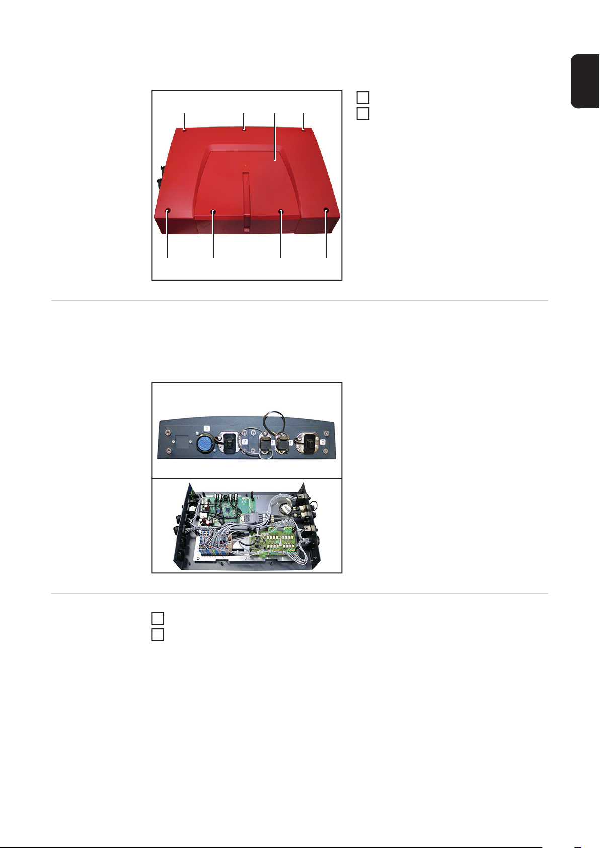
1
Place the interface on a suitable base
2
(1)(1) (2)(1)
Undo the seven screws (1)
1
- TX 25
Remove cover (2)
2
(1)(1)(1)(1)
10

(3)
(4)
(5)
(2) (2) (2) (2)
Secure the four M4 x 10 mm plastic
3
spacers (2)
- 8 mm
- Tightening torque = 0.2 Nm
Place the PC board (6) onto the four
4
short spacers as shown
Secure the PC board (6) with four M4 x
5
30 mm plastic spacers (4)
- 8 mm
- Tightening torque = 0.8 Nm
Connect the system bus lead (3)
6
Connect the 2-pin Molex plug (5)
7
EN
(6)
(4)
(7) (7) (7) (7)
Plug in the four connectors (7) as per
8
the cable labelling on the PC board
11

(9)
(11)
(10)
Remove one of the two blanking co-
9
vers (8)
(8)(8)
Insert the Amphenol plug (10) into the
10
opening from the inside as shown - the
plastic protrusion must be on the right
Secure the Amphenol plug (10) with
11
two cross-head screws (9)
- PH2
Connect all cables to the terminal strip
12
(11) as per the cable labelling
Secure the cables with cable ties
13
(12)
Apply adhesive label X16 (12)
14
12

IMPORTANT! When replacing the cover, ensure that cables are not trapped, crushed,
sheared or damaged in any way.
Replace the cover
(1)(1) (2)(1)
(1)(1)(1)(1)
15
Tighten the seven screws (1)
16
- TX 25
- Tightening torque: 2.5 Nm
EN
Installing the
OPT/i RI REL INT
8I/8O 17P AMP
with an existing
interface
If an interface already exists in the robot interface, install the OPT/i RI REL INT 8I/8O 17P
AMP as described above.
The Amphenol plug is inserted into an available round opening from the inside and secured.
And finally... Return the interface to its original position
1
Restore interface connections to all other system components
2
13

14

EN
15

FRONIUS INTERNATIONAL GMBH
Froniusplatz 1, A-4600 Wels, Austria
Tel: +43 (0)7242 241-0, Fax: +43 (0)7242 241-3940
E-Mail: sales@fronius.com
www.fronius.com
www.fronius.com/addresses
Under http://www.fronius.com/addresses you will find all addresses
of our Sales & service partners and Locations
 Loading...