

Page 1

Fronius prints on elemental chlorine free paper (ECF) sourced from certified sustainable forests (FSC).
/ Perfect Charging / Perfect Welding / Solar Energy
OPT/i RI REL INT 8I/8O 24P Har
Installationsanleitung
DEENFR
Systemerweiterung
Installations instructions
System extension
Instructions d'installation
Extension système
42,0410,2294 001-08022017
Page 2

2
Page 3

Lieferumfang und benötigtes Werkzeug
Lieferumfang
DE
(1)
(2)
(1) OPT/i RI REL INT 8I/8O 24P Har
(2) 20 Buchsenkontakte für Harting-Stecker
(3) 8 Kabelbinder
(4) 4 Kunststoff-Distanzen M4 x 30 mm
(5) 4 Kunststoff-Distanze M4 x 10 mm
(6) Schaltplan (nicht abgebildet)
(7) dieses Dokument (nicht abgebildet)
(3)
(4)
(5)
Benötigtes Werkzeug
- Torx-Schraubendreher TX 25
- Drehmoment-Schlüssel
- Steckschlüssel SW 8 mm
3
Page 4

OPT/i RI REL INT 8I/8O 24P Har einbauen
Sicherheit
WARNUNG! Fehlbedienung und fehlerhaft durchgeführte Arbeiten können
schwerwiegende Personen- und Sachschäden verursachen.
Alle in diesem Dokument beschriebenen Arbeiten und Funktionen dürfen nur von
geschultem Fachpersonal ausgeführt werden, wenn folgende Dokumente vollständig gelesen und verstanden wurden:
- dieses Dokument
- sämtliche Bedienungsanleitungen der Systemkomponenten, insbesondere
Sicherheitsvorschriften
WARNUNG! Ein elektrischer Schlag kann tödlich sein. Vor Beginn der Arbeiten
alle beteiligten Geräte und Komponenten
- ausschalten
- vom Stromnetz trennen
- gegen Wiedereinschalten sichern.
Nach dem Öffnen des Gerätes mit Hilfe eines geeigneten Messgerätes sicherstellen, dass elektrisch geladene Bauteile (z.B. Kondensatoren) entladen sind.
WARNUNG! Unzureichende Schutzleiter-Verbindung kann schwerwiegende
Personen- und Sachschäden verursachen. Die Gehäuse-Schrauben stellen eine
geeignete Schutzleiter-Verbindung für die Erdung des Gehäuses dar und dürfen
keinesfalls durch andere Schrauben ohne zuverlässige Schutzleiter-Verbindung
ersetzt werden.
Vorbereitung Sämtliche Verbindungen des Interfaces von allen anderen Systemkomponenten tren-
OPT/i RI REL INT
8I/8O 24P Har einbauen
1
nen
Interface auf einer geeigneten Unterlage ablegen
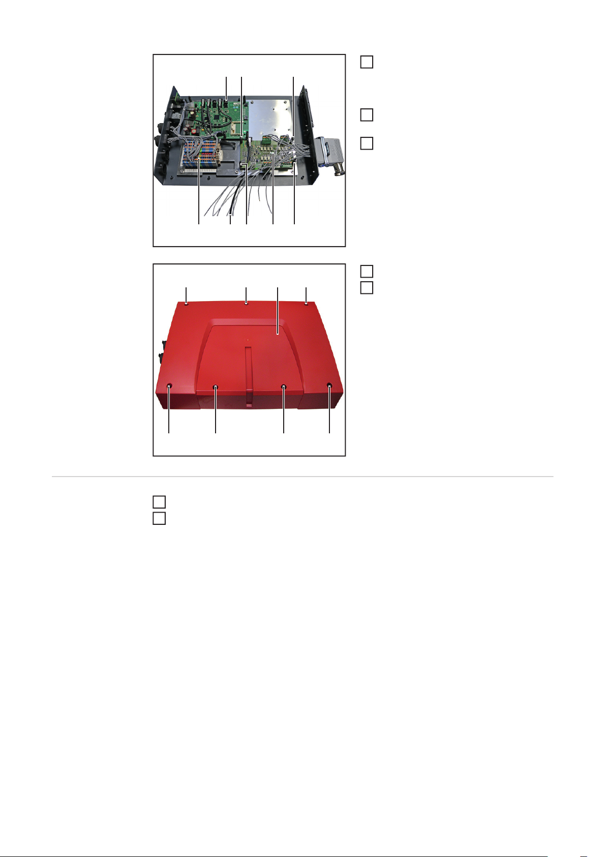
2
(1)(1) (2)(1)
(1)(1)(1)(1)
7 Schrauben (1) lösen
1
- TX 25
Abdeckung (2) entfernen
2
4
Page 5

(3) (4)(3) (3) (3)
(2) (2) (2) (2)
4 Kunststoff-Distanzen M4 x 10 mm (2)
3
festschrauben
- SW 8 mm
- Anzugsmoment = 0,2 Nm
4 Schrauben (3) lösen
4
- TX 25
Abdeckung (4) entfernen
5
DE
(5)
(6)
Print (5) von OPT/i RI REL INT 8I/8O
6
24P Har durch die Öffnung (6) in das
Interface führen und auf die bereits
montieren Kunststoff-Distanzen (2)
aufsetzen
Anschluss Harting (7) mit den zuvor
7
gelösten Schrauben (3) festschrauben
- TX 25
- Anzugsmoment: 2,5 Nm
(3) (7)(3) (3) (3)
5
Page 6

(10)(8) (8)
(9) (8) (8)(5)(11)
Print (5) mit 4 Kunststoff-Distanzen M4
8
x 30 (8) mm festschrauben
- SW 8 mm
- Anzugsmoment = 0,2 Nm
Kabel (9) an Anschluss (10) anschlie-
9
ßen
Die restlichen Kabel von OPT/i RI REL
10
INT 8I/8O 24P Har laut deren Beschriftung an der Klemmleiste (11) anschließen
Abdeckung aufsetzen
(1)(1) (2)(1)
11
7 Schrauben (1) festschrauben
12
- TX 25
- Anzugsmoment: 2,5 Nm
Abschließende
Tätigkeiten
(1)(1)(1)(1)
Interface in seine Ausgangsposition bringen
1
Verbindungen des Interfaces mit anderen Systemkomponenten wieder herstellen
2
6
Page 7

Scope of supply and tools required
Scope of supply
EN
(1)
(2)
(1) OPT/i RI REL INT 8I/8O 24P Har
(2) 20 socket contacts for Harting plug
(3) 8 cable ties
(4) 4 M4 x 30 mm plastic spacers
(5) 4 M4 x 10 mm plastic spacers
(6) Circuit Diagram (not shown)
(7) This document (not shown)
(3)
(4)
(5)
Tools required - TX25 Torx screwdriver
- Torque wrench
- 8 mm box spanner
7
Page 8

Installing OPT/i RI REL INT 8I/8O 24P Har
Safety
WARNING! Incorrect operation or shoddy workmanship can cause serious injury
or damage.
All functions described in this document may only be carried out by trained and
qualified personnel after they have fully read and understood the following documents:
- this document
- all the operating instructions for the system components, especially the safety rules
WARNING! An electric shock can be fatal. Before starting work, ensure that all
devices and components are
- switched off
- disconnected from the mains
- prevented from being switched back on again.
After opening the device, use a suitable measuring instrument to check that electrically charged components (e.g. capacitors) have been discharged.
WARNING! An inadequate ground conductor connection can cause serious injury or damage. The housing screws provide a suitable ground conductor connection for earthing the housing and must NOT be replaced by any other screws that
do not provide a reliable ground conductor connection.
Preparations Disconnect all interface connections from all other system components
Installing OPT/i RI
REL INT 8I/8O 24P
Har
1
Place the interface on a suitable base
2
(1)(1) (2)(1)
Undo the 7 screws (1)
1
- TX 25
Remove the cover (2)
2
(1)(1)(1)(1)
8
Page 9

(3) (4)(3) (3) (3)
(2) (2) (2) (2)
Secure 4 M4 x 10 mm plastic spacers
3
(2) with screws
- 8 mm
- Tightening torque = 0.2 Nm
Undo the 4 screws (3)
4
- TX 25
Remove the cover (4)
5
EN
(5)
(6)
Feed the OPT/i RI REL INT 8I/8O 24P
6
Har PC board (5) through the opening
(6) into the interface and position on
the plastic spacers (2) already fitted
Secure the Harting connection (7) with
7
the previously removed screws (3)
- TX 25
- Tightening torque: 2.5 Nm
(3) (7)(3) (3) (3)
9
Page 10
(10)(8) (8)
(9) (8) (8)(5)(11)
Secure the PC board (5) with 4 M4 x 30
8
mm plastic spacers (8)
- 8 mm
- Tightening torque = 0.2 Nm
Connect the cable (9) to the connecti-
9
on socket (10)
Connect the remaining OPT/i RI REL
10
INT 8I/8O 24P Har cables to the terminal board (11) as per the text on the cable
Replace the cover
(1)(1) (2)(1)
11
Tighten the 7 screws (1)
12
- TX 25
- Tightening torque: 2.5 Nm
(1)(1)(1)(1)
And finally... Return the interface to its original position
1
Restore interface connections to all other system components
2
10
Page 11

Contenu de la livraison et outillage nécessaire
Contenu de la livraison
(1) OPT/i RI REL INT 8I/8O 24P Har
(1)
(2)
(3)
(4)
(5)
FR
Outillage nécessaire
(2) 20 contacts femelles pour prise Harting
(3) 8 attache-câbles
(4) 4 pièces d'écartement en plastique M4 x 30 mm
(5) 4 pièces d'écartement en plastique M4 x 10 mm
(6) Schéma de câblage (non représenté)
(7) Le présent document (non représenté)
- Tournevis Torx TX 25
- Clé dynamométrique
- Clé à douille SW 8 mm
11
Page 12

Monter l'option OPT/i RI REL INT 8I/8O 24P Har
Sécurité
AVERTISSEMENT ! Les erreurs de commande et les erreurs en cours d'opéra-
tion peuvent entraîner des dommages corporels et matériels graves.
L'ensemble des opérations et travaux décrits dans le présent document ne
doivent être effectués que par du personnel qualifié ayant lu et compris l'intégralité des documents suivants :
- le présent document
- toutes les Instructions de service des composants périphériques, en particulier les consignes de sécurité
AVERTISSEMENT ! Une décharge électrique peut être mortelle. Avant le début
des travaux,
- déconnecter tous les appareils et composants impliqués
- débrancher du réseau électrique
- s'assurer de l'impossibilité de reconnecter tous les appareils et composants
concernés.
Après ouverture de l'appareil, s'assurer, à l'aide d'un appareil de mesure approprié, que les composants à charge électrique (condensateurs, par ex.) sont déchargés.
AVERTISSEMENT ! Une connexion de conducteur de terre insuffisante peut entraîner de graves dommages corporels et matériels. Les vis du boîtier constituent
une connexion de conducteur de terre appropriée pour la mise à la terre du corps
de l'appareil. Il ne faut en aucun cas remplacer ces vis par d'autres vis qui n'offriraient pas ce type de connexion de conducteur de terre fiable.
Préparation Débrancher toutes les connexions de l'interface avec tous les autres composants pé-
Monter l'option
OPT/i RI REL INT
8I/8O 24P Har
1
riphériques
Placer l'interface sur un support adapté
2
(1)(1) (2)(1)
Desserrer les 7 vis (1)
1
- TX 25
Retirer le cache (2)
2
(1)(1)(1)(1)
12
Page 13

(3) (4)(3) (3) (3)
(2) (2) (2) (2)
Visser fermement les 4 pièces d'écar-
3
tement en plastique M4 x 10 mm (2)
- Ouverture de clé 8 mm
- Couple de serrage = 0,2 Nm
Desserrer les 4 vis (3)
4
- TX 25
Retirer le cache (4)
5
FR
(5)
(6)
Insérer le circuit imprimé (5) de l'option
6
OPT/i RI REL INT 8I/8O 24P Har à travers l'ouverture (6) dans l'interface et
le placer sur les pièces d'écartement
en plastique (2) déjà montées
Visser fermement le connecteur Har-
7
ting (7) à l'aide des vis (3) desserrées
auparavant
- TX 25
- Couple de serrage : 2,5 Nm
(3) (7)(3) (3) (3)
13
Page 14

(10)(8) (8)
(9) (8) (8)(5)(11)
Fixer le circuit imprimé (5) à l'aide des
8
quatre pièces d'écartement en plastique M4 x 30 mm (8)
- Ouverture de clé 8 mm
- Couple de serrage = 0,2 Nm
Raccorder le câble (9) au connecteur
9
(10)
Raccorder les câbles restants de l'opti-
10
on OPT/i RI REL INT 8I/8O 24P Har au
bornier (11) conformément à ce qui y
est inscrit
Remettre le cache en place
(1)(1) (2)(1)
11
Visser fermement les 7 vis (1)
12
- TX 25
- Couple de serrage : 2,5 Nm
(1)(1)(1)(1)
Étapes finales Replacer l'interface dans sa position initiale
1
Rétablir la connexion de l'interface avec les autres composants périphériques
2
14
Page 15

FR
15
Page 16

FRONIUS INTERNATIONAL GMBH
Froniusplatz 1, A-4600 Wels, Austria
Tel: +43 (0)7242 241-0, Fax: +43 (0)7242 241-3940
E-Mail: sales@fronius.com
www.fronius.com
www.fronius.com/addresses
Under http://www.fronius.com/addresses you will find all addresses
of our Sales & service partners and Locations
 Loading...