


Fronius prints on elemental chlorine free paper (ECF) sourced from certified sustainable forests (FSC).
/ Perfect Charging / Perfect Welding / Solar Energy
OPT/i RI FB active/deactive
OPT/i RI FB active/deactive
Installationsanleitung
DE
Roboter-Option
Installation instructions
Robot option
EN-US
42,0410,2612 001-11082020


Inhaltsverzeichnis
Allgemeines 4
Lieferumfang 4
Erforderliche Werkzeuge 4
OPT/i RI FB active/deactive einbauen 5
Sicherheit 5
OPT/i RI FB active/deactive einbauen 5
DE
3

Allgemeines
Lieferumfang
Erforderliche
Werkzeuge
- Torx-Schraubendreher TX20
- Torx-Schraubendreher TX25
4
OPT/i RI FB active/deactive einbauen
1
1
1
1
4x TX25
2
DE
Sicherheit
WARNUNG!
Fehlbedienung und fehlerhaft durchgeführte Arbeiten können schwerwiegende
Personen- und Sachschäden verursachen.
Alle in diesem Dokument beschriebenen Arbeiten und Funktionen dürfen nur von
▶
geschultem Fachpersonal ausgeführt werden.
Alle in diesem Dokument beschriebenen Arbeiten und Funktionen dürfen nur aus-
▶
geführt werden, wenn folgende Dokumente vollständig gelesen und verstanden wurden:
dieses Dokument,
sämtliche Bedienungsanleitungen der Systemkomponenten, insbesondere Sicherheitsvorschriften.
WARNUNG!
Ein elektrischer Schlag kann tödlich sein.
Vor Beginn der Arbeiten alle beteiligten Geräte und Komponenten ausschalten, vom
▶
Stromnetz trennen und gegen Wiedereinschalten sichern.
Nach dem Öffnen des Gerätes mit Hilfe eines geeigneten Messgerätes sicherstel-
▶
len, dass elektrisch geladene Bauteile (z.B. Kondensatoren) entladen sind.
WARNUNG!
OPT/i RI FB
active/deactive
einbauen
Unzureichende Schutzleiter-Verbindung kann schwerwiegende Personen- und
Sachschäden verursachen.
Die Gehäuse-Schrauben stellen eine geeignete Schutzleiter-Verbindung für die Erdung
des Gehäuses dar.
Die Gehäuse-Schrauben dürfen keinesfalls durch andere Schrauben ohne
▶
zuverlässige Schutzleiter-Verbindung ersetzt werden.
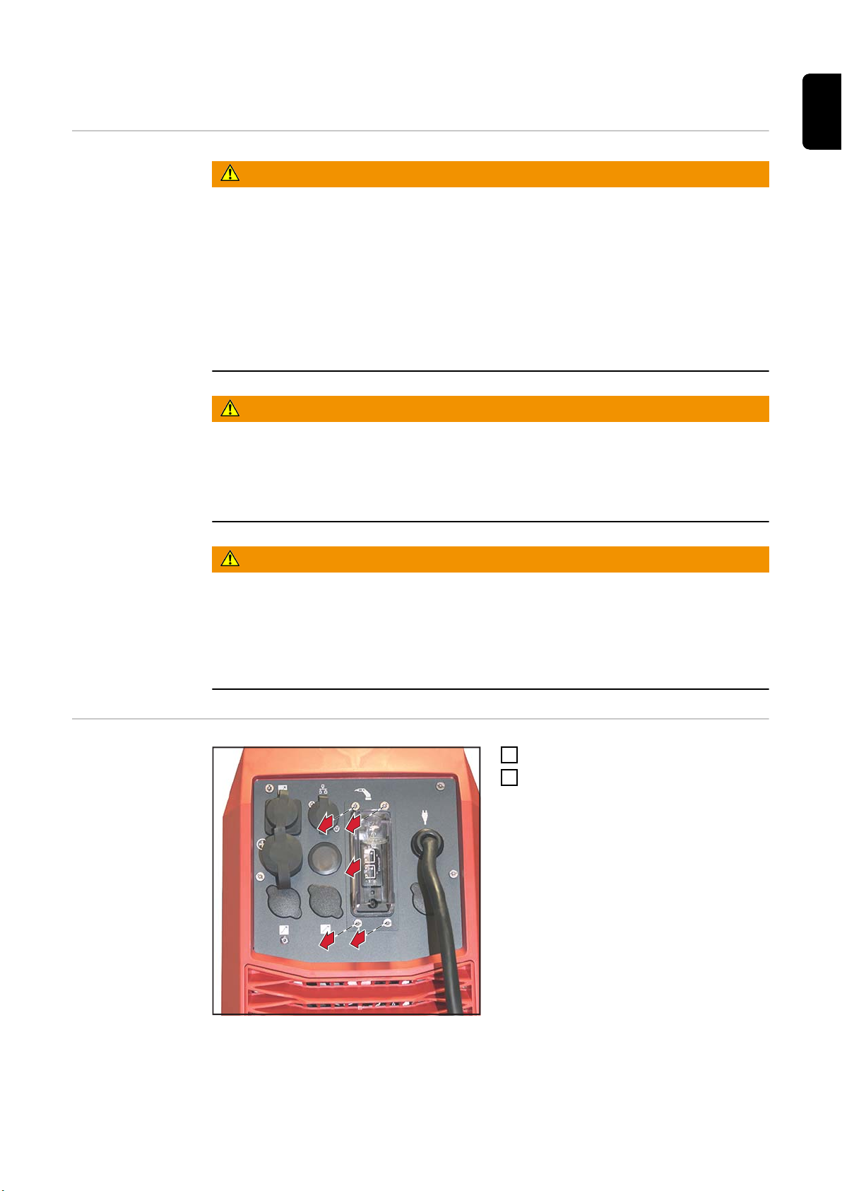
4 Schrauben TX25 entfernen
1
Interface so weit wie möglich heraus
2
ziehen
5

3
Blindabdeckung von innen nach
5
4
5
2x TX20
6
3
außen herausdrücken
WICHTIG! Beim Einsetzen des Schalters
darauf achten, dass die Pfeilspitze nach
oben zeigt.
Schalter durch die eckige Öffnung in
4
das Gerät einführen und dann von
innen nach außen in die runde
Öffnung einsetzen
Schalter mit 2 Schrauben TX20 fixie-
5
ren
Kabel vom Interface-Print abstecken
6
6

7
8
8
9
Kabel vom Schalter am Interface-Print
4x TX25
10
11
10
10
10
7
anstecken
2. Kabel vom Schalter mit dem Kabel
8
aus der Stromquelle zusammenstecken
Interface einsetzen
9
Interface mit 4 Schrauben TX25 fixie-
10
ren
Aufkleber ON/OFF oberhalb des
11
Schalters anbringen
DE
7

8

Table of contents
General 10
Scope of supply 10
Tools required 10
Installing the OPT/i RI FB active/deactive 11
Safety 11
Installing the OPT/i RI FB active/deactive 11
EN-US
9

General
Scope of supply
Tools required - Torx screwdriver TX20
- Torx screwdriver TX25
10

Installing the OPT/i RI FB active/deactive
1
1
1
1
4x TX25
2
Safety
WARNING!
Incorrect operation and incorrectly performed work can cause serious injury and
property damage.
All the work and functions described in this document must only be carried out by
▶
trained and qualified personnel.
Do not perform any of the work and functions described in this document until you
▶
have thoroughly read and understood the following:
This document
All Operating Instructions for system components, especially the safety rules
WARNING!
An electric shock can be fatal.
Before starting work, switch off all devices and components involved, disconnect
▶
from the grid, and secure to prevent them from being switched back on again.
After opening the device, use a suitable measuring instrument to ensure that electri-
▶
cally charged components (e.g., capacitors) are discharged.
WARNING!
An inadequate ground conductor connection can cause serious injury and
damage to property.
The housing screws act as a ground conductor connection for grounding the housing.
The housing screws must not under any circumstances be replaced by other screws
▶
without a reliable ground conductor connection.
EN-US
Installing the
OPT/i RI FB
active/deactive
Remove the four TX25 screws
1
Pull out the interface as far as possi-
2
ble
11

3
Push out the dummy cover from the
5
4
5
2x TX20
6
3
inside out
IMPORTANT! When inserting the switch,
make sure that the arrow tip is pointing
upwards.
Insert the switch into the device
4
through the square opening and then
insert it into the round opening from
the inside out
Secure the switch with two TX20
5
screws
Disconnect the cable from the inter-
6
face PC board
12

7
8
8
9
Connect the cable from the switch to
4x TX25
10
11
10
10
10
7
the interface PC board
Connect the second cable from the
8
switch to the cable from the power
source
Insert the interface
9
Secure the interface with four TX25
10
screws
Affix the ON/OFF sticker above the
11
switch
EN-US
13

14

EN-US
15

FRONIUS INTERNATIONAL GMBH
Froniusstraße 1
A-4643 Pettenbach
AUSTRIA
contact@fronius.com
www.fronius.com
Under www.fronius.com/contact you will find the addresses
of all Fronius Sales & Service Partners and locations.
 Loading...