


/ Battery Charging Systems / Welding Technology / Solar Electronics
VR 2000
VR 4000
VR 7000
Einbauanleitung
Option Betriebswahlschalter
DEENFR
Installation instructions
Optional mode selector
Instructions d´installation
Option commutateur de
sélection de mode de service
42,0410,0856 002-28032012


Sehr geehrter Leser
DE
Einleitung
Wir danken Ihnen für Ihr entgegengebrachtes Vertrauen und gratulieren Ihnen zu Ihrem
technisch hochwertigen Fronius Produkt. Die vorliegende Anleitung hilft Ihnen, sich mit
diesem vertraut zu machen. Indem Sie die Anleitung sorgfältig lesen, lernen Sie die
vielfältigen Möglichkeiten Ihres Fronius-Produktes kennen. Nur so können Sie seine
Vorteile bestmöglich nutzen.
Bitte beachten Sie auch die Sicherheitsvorschriften und sorgen Sie so für mehr Sicherheit am Einsatzort des Produktes. Sorgfältiger Umgang mit Ihrem Produkt unterstützt
dessen langlebige Qualität und Zuverlässigkeit. Das sind wesentliche Voraussetzungen
für hervorragende Ergebnisse.
ud_fr_st_et_00491 01/2012


Inhaltsverzeichnis
Allgemeines .................................................................................................................................................. 2
Allgemeines ............................................................................................................................................. 2
Erforderliche Software ............................................................................................................................. 2
Bauteile .................................................................................................................................................... 2
Erforderliche Werkzeuge und Hilfsmittel .................................................................................................. 3
Einbauset Betriebswahlschalter in Drahtvorschub VR 2000 einbauen ......................................................... 4
Vorbereitende Tätigkeiten am Vorschub .................................................................................................. 4
Vorbereitende Tätigkeiten am Betriebswahlschalter................................................................................ 4
Betriebswahlschalter einbauen ................................................................................................................ 6
Abschließende Tätigkeiten ....................................................................................................................... 8
Einbauset Betriebswahlschalter in Drahtvorschub VR 4000 und VR 7000 einbauen................................... 9
Vorbereitende Tätigkeiten am Vorschub .................................................................................................. 9
Vorbereitende Tätigkeiten am Betriebswahlschalter...............................................................................11
Betriebswahlschalter einbauen .............................................................................................................. 12
Abschließende Tätigkeiten ..................................................................................................................... 15
Bohrschablonen .......................................................................................................................................... 16
Allgemeines ........................................................................................................................................... 16
Bohrschablone VR 4000 ........................................................................................................................ 16
Bohrschablone VR 7000 ........................................................................................................................ 17
DE
1

Allgemeines
Allgemeines
Erforderliche
Software
Bauteile
Die Option Einbauset Betriebswahlschalter dient zur nachträglichen Ausstattung der
Drahtvorschübe VR 2000, VR 4000 und VR 7000 mit dem Betriebswahlschalter.
Hinweis! Ist der Vorschub mit dem Bedienpanel TR 4000 C ausgestattet, kann
die Option Betriebswahlschalter nicht verwendet werden.
Warnung! Fehlerhaft durchgeführte Arbeiten können schwerwiegende Personenund Sachschäden verursachen. Nachfolgend beschriebene Tätigkeiten dürfen
nur von Fronius-geschultem Fachpersonal durchgeführt werden! Beachten Sie
die Sicherheitsvorschriften in der Bedienungsanleitung der Stromquelle.
Vor Öffnen des Gerätes:
- Netzschalter der Stromquelle in Stellung „O“ schalten
- Netzstecker der Stromquelle ziehen
- Verbindungen zwischen Vorschub und Stromquelle trennen
- Schweißbrenner abschließen
Für den Betrieb des Betriebswahlschalters ist folgende Firmware an der Stromquelle
erforderlich: Firmware OFFICIAL UST V2.80.1
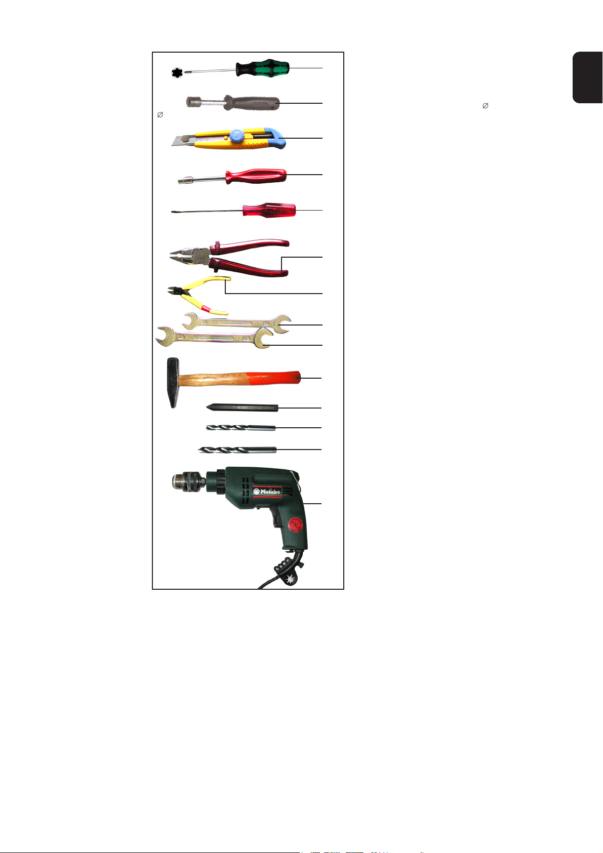
Das Einbauset Betriebswahlschalter (4,100,360) besteht aus folgenden Bauteilen:
(1)(9) (8) (7)(6) (5) (4)(3) (2)
Abb1. Einbauset Betriebswahlschalter VR 2000
(1) Print FPWS 1 ............................................. 1 Stk. ......................................4,070,790
(2) Flachbandkabel 10-polig, 310 mm ............. 1 Stk. ................................ 43,0004,2142
(3) Drehknopf schwarz .................................... 2 Stk. ................................42,0406,0099
(4) Mutterabdeckung rot .................................. 2 Stk. ................................42,0406,0213
(5) Drehknopfdeckel rot ................................... 2 Stk. ................................42,0406,0109
(6) Rundmutter M10x1, D=13x3 ...................... 2 Stk. ................................ 42,0400,0115
(7) Dichtung chrom .......................................... 1 Stk. ................................ 42,0406,0224
(8) ESD-Beutel 152x254 mm, rosa ................. 1 Stk. ................................ 40,0001,0404
(9) Kabelbinder 150 ......................................... 2 Stk. ................................ 42,0407,0100
(10) Klebeetikette Betriebswahlschalter ............ 1 Stk. ................................ 42,0409,2894
(11) Einbauanleitung (ohne Abb.)...................... 1 Stk. ................................ 42,0410,0856
2
(10)
Erforderliche
Werkzeuge und
Hilfsmittel
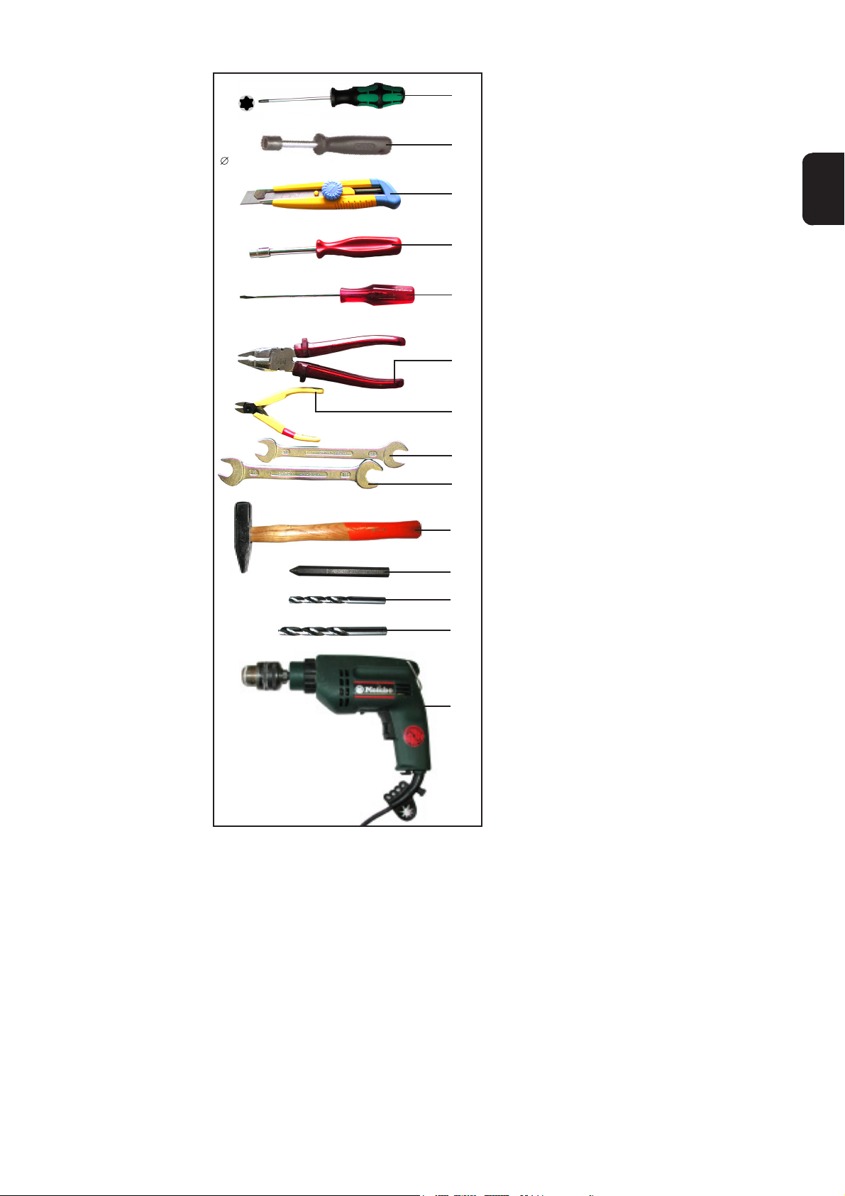
TX25
(A)
(A) Handschraubendreher TX25
(B) Steckschlüssel SW7
DE
13 mm
SW7
SW17
SW14
(C)
(G)
(B)
(I)
(H)
(F)
(E)
(D)
(K)
(J)
(M)
(N)
(C) Rundmutternschlüssel 13 mm
(D) Gabelschlüssel SW17
(E) Gabelschlüssel SW14
(F) Seitenschneider
(G) Stanleymesser
(H) Kombizange
(I) Schlitz-Schraubendreher
(J) Körner
(K) Hammer
(L) Bohrmaschine
(M) Metall-Bohrer Durchmesser 11 mm
(N) Metall-Bohrer Durchmesser 12,5 mm
Wichtig! Die Werkzeuge (K) - (N) werden
nur für Vorschübe benötigt, bei denen
noch keine Bohrungen für die Option
Betriebswahlschalter vorhanden sind.
Abb2. Erforderliche Werkzeuge
(L)
3

Einbauset Betriebswahlschalter in Drahtvorschub
VR 2000 einbauen
Vorbereitende
Tätigkeiten am
Vorschub
(A)
(b)
(a)
Abb.3 Gehäuse abnehmen
(c)
1. Seitenteil links (b) öffnen
2. Extrude-Tite-Schrauben auf Vorschub-Oberseite und Vorschub-Seite
mittels Handschraubendreher TX25
(A) herausschrauben
3. Gehäuse (a) nach oben abnehmen
4. Blindabdeckungen (c) entfernen
Die Blindabdeckungen werden nicht
mehr benötigt.
Vorbereitende
Tätigkeiten am
Betriebswahlschalter
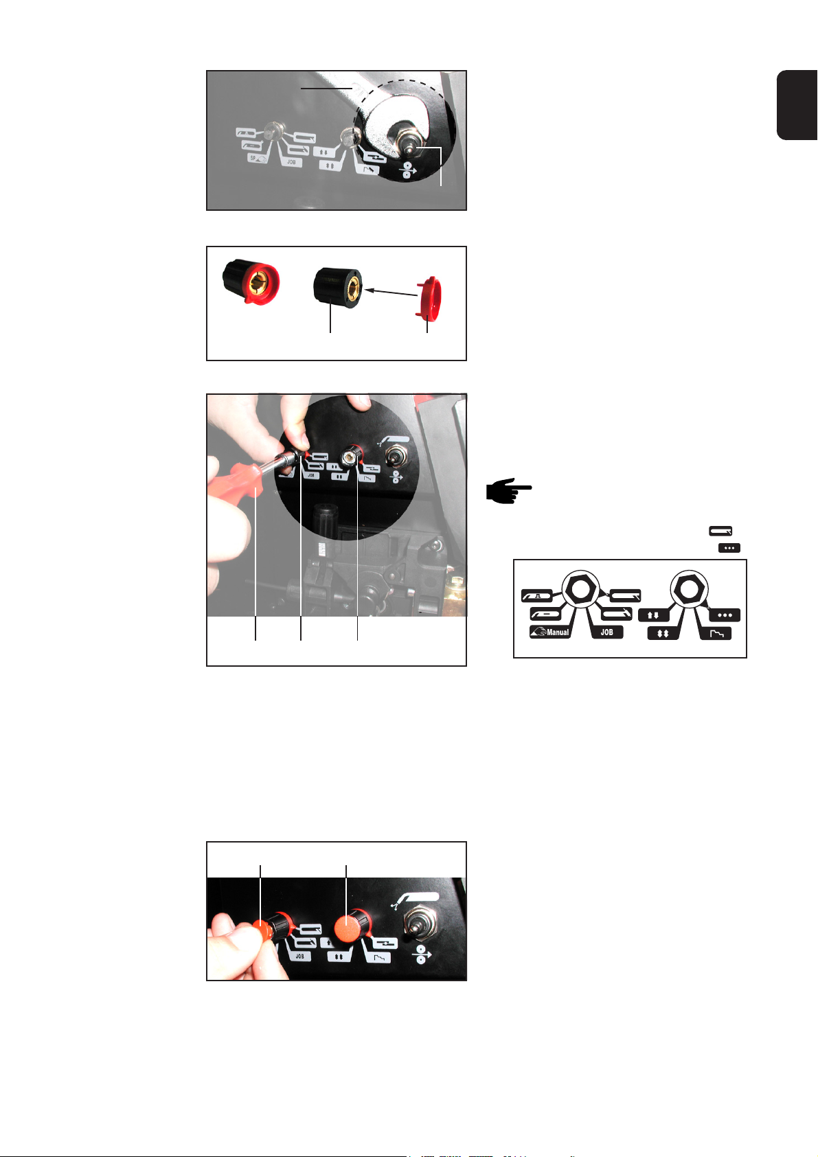
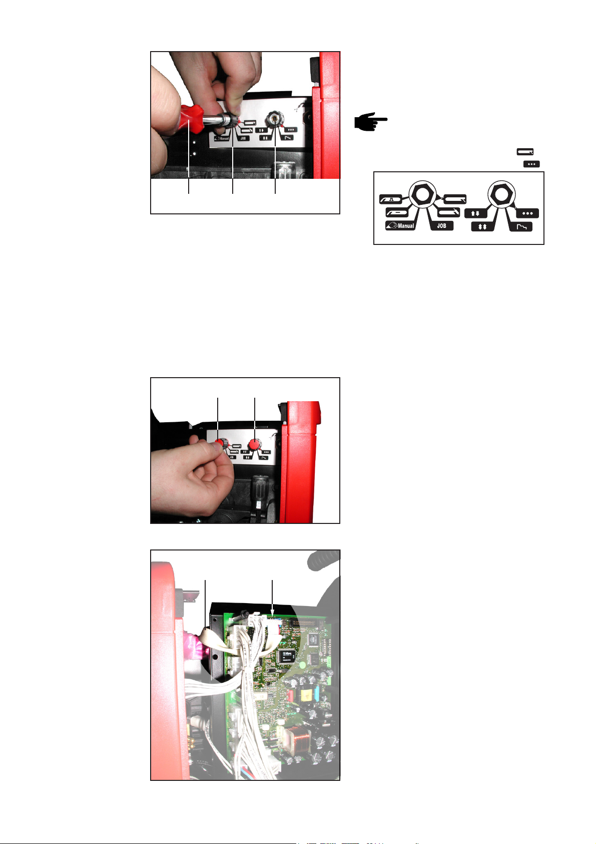
Abb.4 Blindabdeckungen entfernen
5. Sechskantmuttern von Wahlschaltern
und Taster mittels Gabelschlüssel
SW14 (E) entfernen
Wichtig! Vom Taster nur die oberste
Sechskantmutter entfernen, die
untere Sechskantmutter und die
Scheibe bleiben am Taster.
Die Sechskantmuttern werden nicht
mehr benötigt.
(E)
Abb.5 Sechskantmuttern entfernen
4

Vorbereitende
Tätigkeiten am
Betriebswahlschalter
(Fortsetzung)
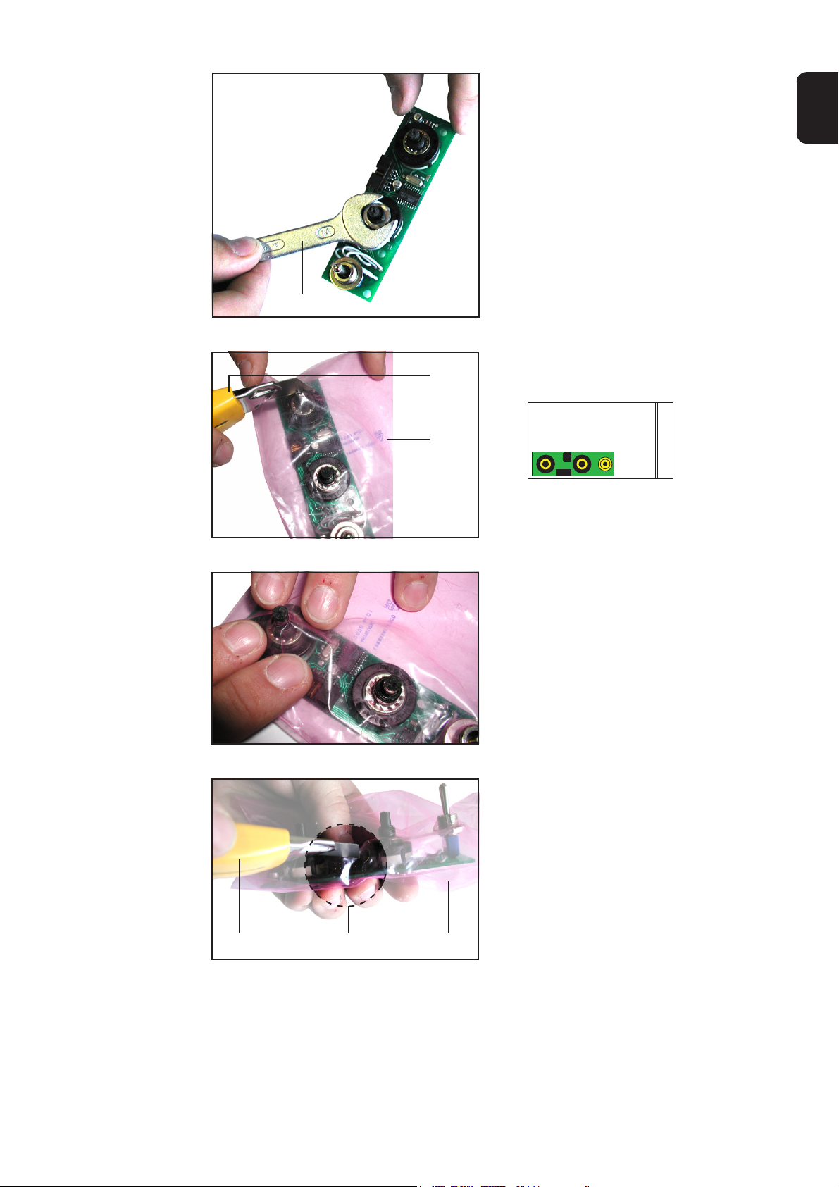
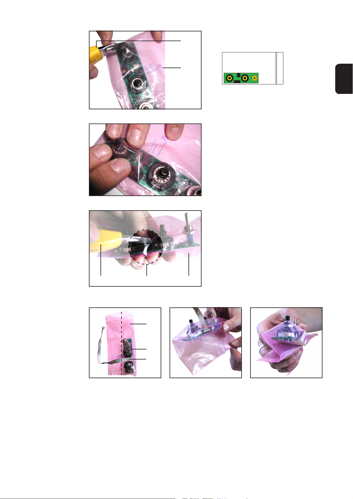
Abb.6 ESD-Beutel einschneiden
Abb.7 Folie nach unten drücken
(G)
(8)
6. Print FPWS 1 (1) in ESD-Beutel (8)
geben - zum Schutz vor Staub- und
Feuchtigkeit
7. ESD-Beutel (8) mittels Stanleymesser
(G) kreuzweise über Wahlschaltern
und Taster einschneiden
8. Beutelfolie nach unten drücken,
sodaß Wahlschalter und Taster bis
zum Gewinde freiliegen
DE
(d)
Abb.8 Stecker für Flachbandkabel ausschneiden
(8)(G)
(8)
(1)
(2)
Abb.9a Flachbandkabel anstek-
ken
Abb.9b ESD-Beutel um Print
falten ...
9. Stecker für Flachbandkabel (d) mittels
Stanleymesser (G) aus ESD-Beutel
(8) ausschneiden
Abb.9c ... S-förmig
10. Flachbandkabel (2) von außerhalb des ESD-Beutels (8) gemäß Abbildung 9a am
Print (1) anstecken
11. ESD-Beutel (8) entlang der Print-Längsseite S-förmig um Print (1) falten, sodaß die
Beutel-Außenkante auf Höhe der Print-Mitte liegt
5

Vorbereitende
Tätigkeiten am
Betriebswahlschalter
(Fortsetzung)
12. Überstehendes Ende des ESDBeutels (8) entlang der Print-Stirnseite unter Print (1) falten
(8)
(1)
Abb.10 ESD-Beutel falten
13. ESD-Beutel (8) mittels Kabelbinder
(9) am Print (1) fixieren
14. Kabelbinder (9) mittels Seitenschneider (F) ablängen
Betriebswahlschalter einbauen
(9)
Abb.11 ESD-Beutel am Print fixieren
Abb.12a Print in Vorschub einsetzen
(9)(8)
(6)
(6)
(1)
1. Print in Vorschub einsetzen:
- Flachbandkabel oben
- Wahlschalter bzw. Taster in die
vorgesehenen Bohrungen
Abb.12b Detailansicht Lage Flachbandkabel
2. Rundmuttern (6) auf WahlschalterGewinde aufschrauben
3. Rundmuttern mittels Rundmutternschlüssel 13 mm (C) festziehen
(B)
Abb.13 Rundmuttern aufschrauben
6
Betriebswahlschalter einbauen
(Fortsetzung)
(D)
Abb.14 Dichtung chrom aufschrauben
Abb.15 Drehknopf zusammenstecken
4. Dichtung chrom (7) auf TasterGewinde aufschrauben
5. Dichtung chrom (7) mittels Gabel-
DE
schlüssel SW17 (D) festziehen
(7)
6. 2 x Drehknopf (3) und Mutterabdekkung (4) zusammenstecken
(4)(3)
7. Wahlschalter mittels Kombizange (H)
bis zum Anschlag nach links drehen
8. Drehknopf mit Mutterabdeckung (3+4)
auf Wahlschalter aufstecken
(B)
(3+4) (3+4)
Abb.16a Drehknöpfe befestigen
(5)(5)
Hinweis! Die Pfeilspitze der
Mutterabdeckung soll auf folgende Symbole zeigen:
- linker Wahlschalter auf
- rechter Wahlschalter auf
Abb.16b Pfeilspitzen und Symbole
9. Drehknöpfe befestigen:
- Drehknöpfe mit Mutterabdeckung
(3+4) festhalten
- mittels Steckschlüssel SW7 (B)
festziehen
- Kontrolle, ob beim Drehen der
Drehknöpfe die Pfeilspitzen auf die
entsprechenden Symbole zeigen
10. 2 x Drehknopfdeckel (5) in Drehknopf
einsetzen
Abb.17 Drehknopfdeckel einsetzen
7

Betriebswahlschalter einbauen
(Fortsetzung)
(X2) (2)
Abb.18 Flachbandkabel am Print anstecken
(e)
11. Flachbandkabel (2) am Print SR 41
anstecken:
- Flachbandkabel (2) in Ausneh-
mung (e)
- Flachbandkabel (2) am Stecker
RS485 (X2) anstecken
Abschließende
Tätigkeiten
(A)
(b)
(a)
Abb.19 Gehäuse aufsetzen
1. Gehäuse (a) aufsetzen
Beim Aufsetzen des Gehäuses auf
folgendes achten:
- Flachbandkabel nicht einklemmen
- Flachbandkabel in Ausnehmung
(e)
2. Extrude-Tite-Schrauben auf Vorschub-Oberseite und Vorschub-Seite
mittels Handschraubendreher TX25
(A) einschrauben
3. Seitenteil links (b) schließen
8

Einbauset Betriebswahlschalter in Drahtvorschub
VR 4000 und VR 7000 einbauen
DE
Vorbereitende
Tätigkeiten am
Vorschub
(A)
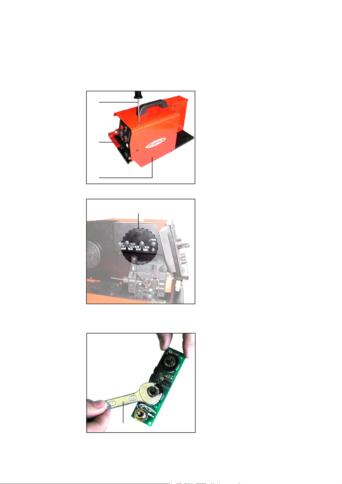
Abb.20 Gehäuse abnehmen
1. Seitenteil links (b) öffnen
2. Extrude-Tite-Schrauben auf Vorschub-Oberseite und Vorschub-Seite
mittels Handschraubendreher TX25
(A) herausschrauben
3. Gehäuse (a) nach oben abnehmen
(b)
(a)
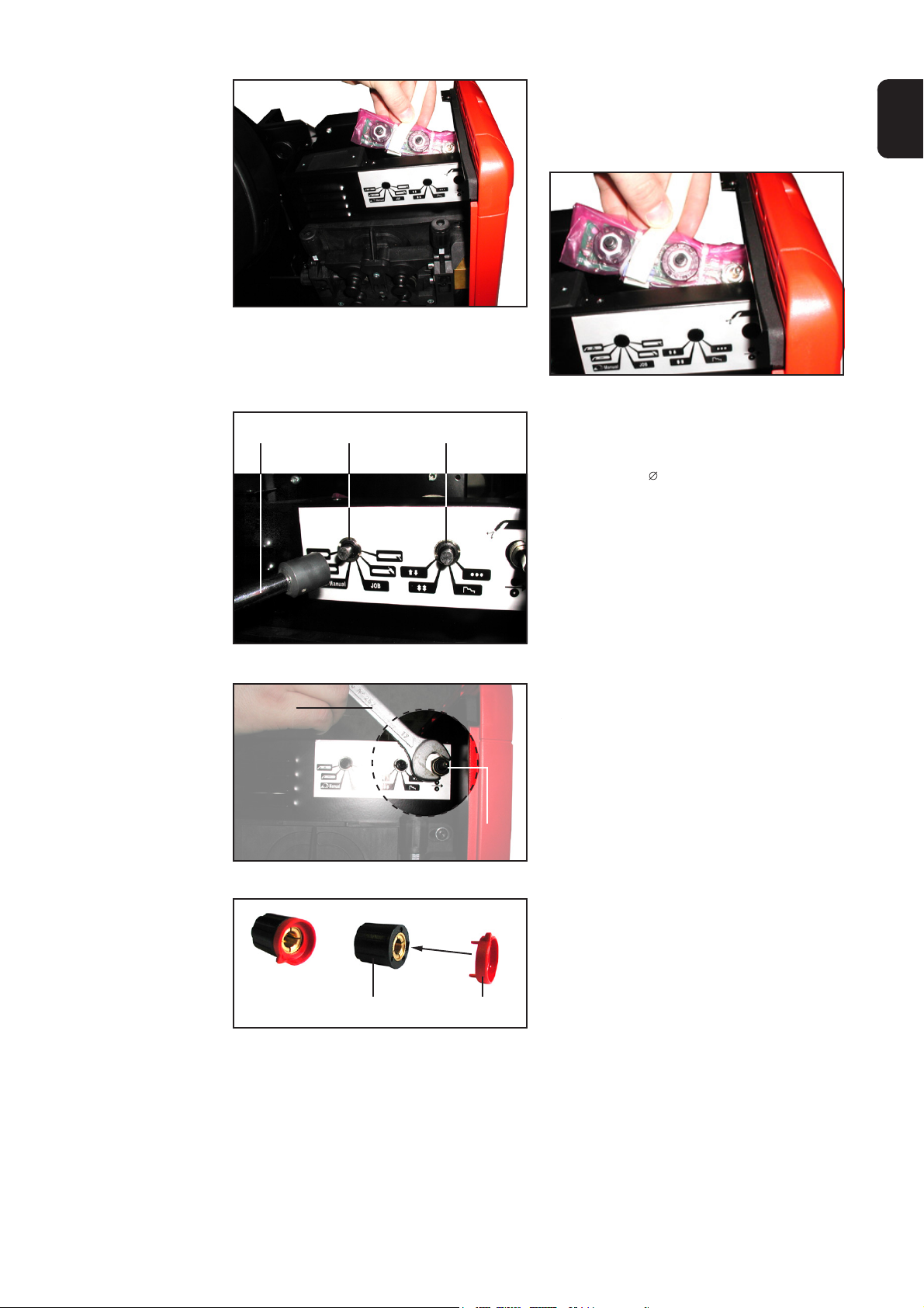
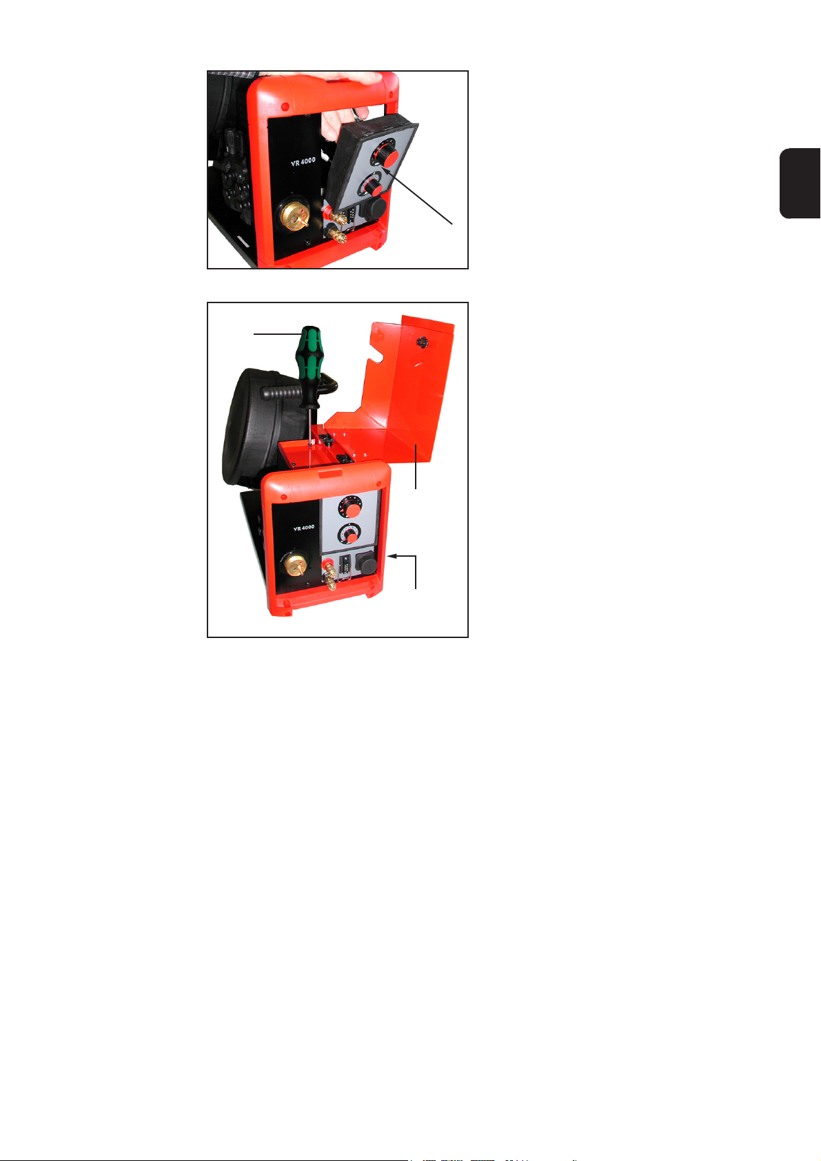
4. Vorschub-Bedienpanel vorsichtig von
innen nach außen herausdrücken
Abb.21 Bedienpanel herausdrücken
(c)
Abb.22 Blindabdeckungen entfernen
5. Blindabdeckungen (c) entfernen
Die Blindabdeckungen werden nicht
mehr benötigt.
9

Vorbereitende
Tätigkeiten am
Vorschub
(Fortsetzung)
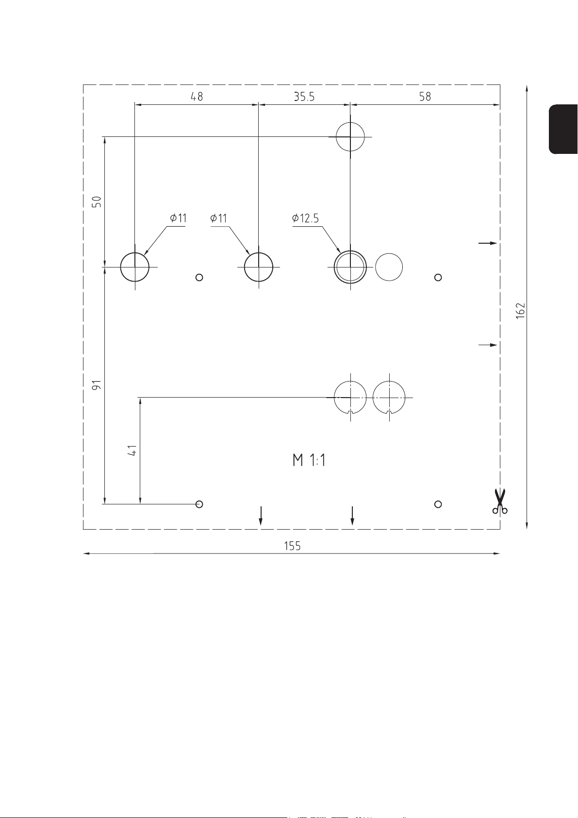
Sind am Drahtvorschub keine Bohrungen und Blindabdeckungen vorhanden, die Bohrungen für den Betriebswahlschalter wie folgt anbringen:
- Bohrschablone ausschneiden
- Bohrschablone gemäß Abbildung ansetzen:
- Unterkante Bohrschablone auf Oberkante Motorplatte
- Rechte Kante Bohrschablone an Vorschub-Front
- Position der Bohrungen mittels Hammer (K) und Körner (J) ankörnen
- Bohrschablone entfernen
- mittels Metallbohrer (M) und Bohrmaschine (L) 2 Bohrungen mit Durchmesser 11
mm bohren
- mittels Metallbohrer (N) und Bohrmaschine (L) 1 Bohrung mit Durchmesser 12,5
mm bohren
Bohrschablone Bohrschablone
Abb.23 Position der Bohrschablone am VR 4000 Abb.24 Position der Bohrschablone am VR 7000
10
Vorbereitende
Tätigkeiten am
Betriebswahlschalter
(E)
Abb.25 Sechskantmuttern entfernen
(G)
(8)
6. Sechskantmuttern von Wahlschaltern
und Taster mittels Gabelschlüssel
SW14 (E) entfernen
Wichtig! Vom Taster nur die oberste
Sechskantmutter entfernen, die
untere Sechskantmutter und die
Scheibe bleiben am Taster.
Die Sechskantmuttern werden nicht
mehr benötigt.
7. Print FPWS 1 (1) in ESD-Beutel (8)
geben - zum Schutz vor Staub- und
Feuchtigkeit
DE
Abb.26 ESD-Beutel einschneiden
Abb.27 Folie nach unten drücken
8. ESD-Beutel (8) mittels Stanleymesser
(G) kreuzweise über Wahlschaltern
und Taster einschneiden
9. Beutelfolie nach unten drücken,
sodaß Wahlschalter und Taster bis
zum Gewinde freiliegen
10. Stecker für Flachbandkabel (d) mittels
Stanleymesser (G) aus ESD-Beutel
(8) ausschneiden
(8)(G) (d)
Abb.28 Stecker für Flachbandkabel ausschneiden
11

Vorbereitende
Tätigkeiten am
Betriebswahlschalter
(Fortsetzung)
(8)
(1)
(2)
Abb.29a Flachbandkabel anstek-
ken
Abb.29b ESD-Beutel um Print
falten ...
Abb.29c ... S-förmig
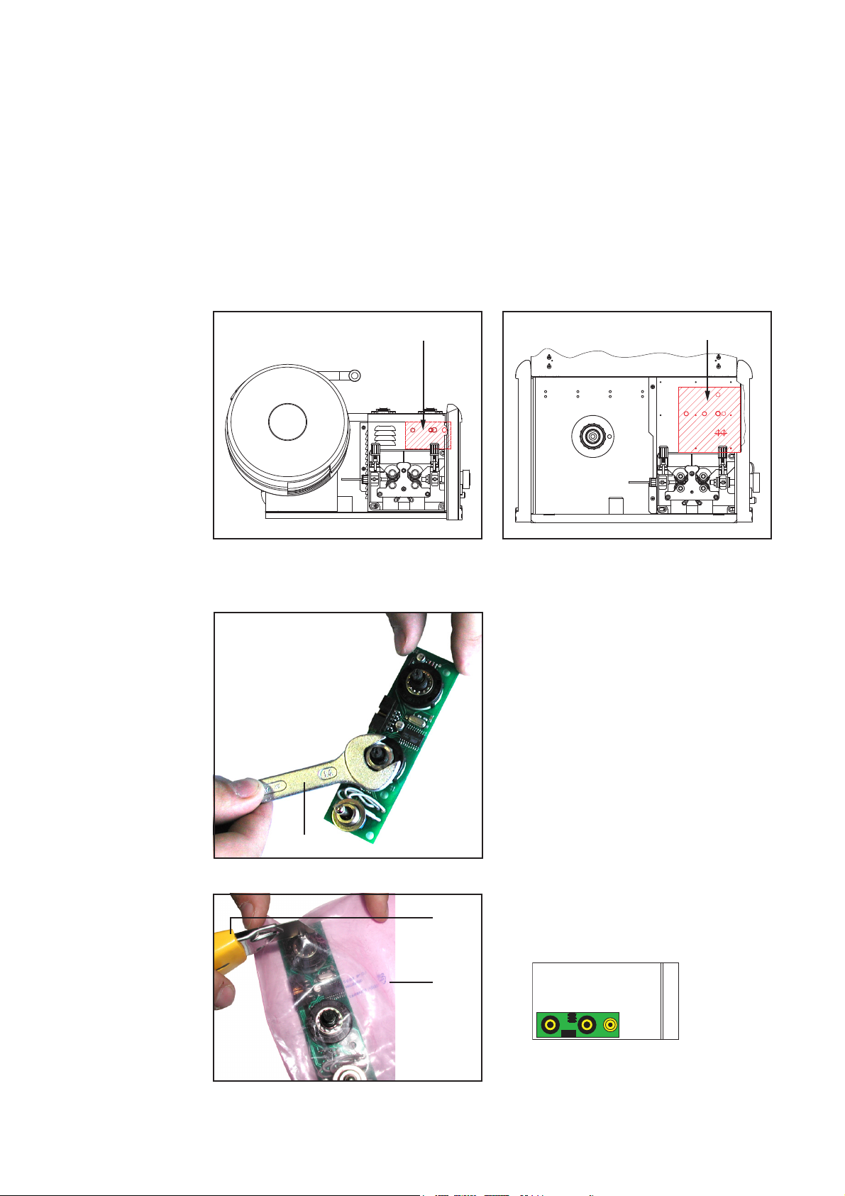
11. Flachbandkabel (2) von außerhalb des ESD-Beutels (8) gemäß Abbildung 29a am
Print (1) anstecken
12. ESD-Beutel (8) entlang der Print-Längsseite S-förmig um Print (1) falten, sodaß die
Beutel-Außenkante auf Höhe der Print-Mitte liegt
13. Überstehendes Ende des ESDBeutels (8) entlang der Print-Stirnseite unter Print (1) falten
(8)
(1)
Abb.30 ESD-Beutel falten
14. ESD-Beutel (8) mittels Kabelbinder
(9) am Print (1) fixieren
15. Kabelbinder (9) mittels Seitenschnei-
der (F) ablängen
Betriebswahlschalter einbauen
(9)
Abb.31 ESD-Beutel am Print fixieren
(10)
Abb.32 Klebeetikette aufkleben
12
(9)(8)
(1)
1. Klebeetikette Betriebswahlschalter
(10) aufkleben
Wichtig! Die Klebeetikette so aufkleben, daß die ausgestanzten Flächen
genau über den Bohrungen positioniert werden.
Betriebswahlschalter einbauen
(Fortsetzung)
Abb.33a Print in Vorschub einsetzen
2. Print in Vorschub einsetzen:
- Flachbandkabel oben
- Wahlschalter bzw. Taster in die
vorgesehenen Bohrungen
Abb.33b Detailansicht Lage Flachbandkabel
DE
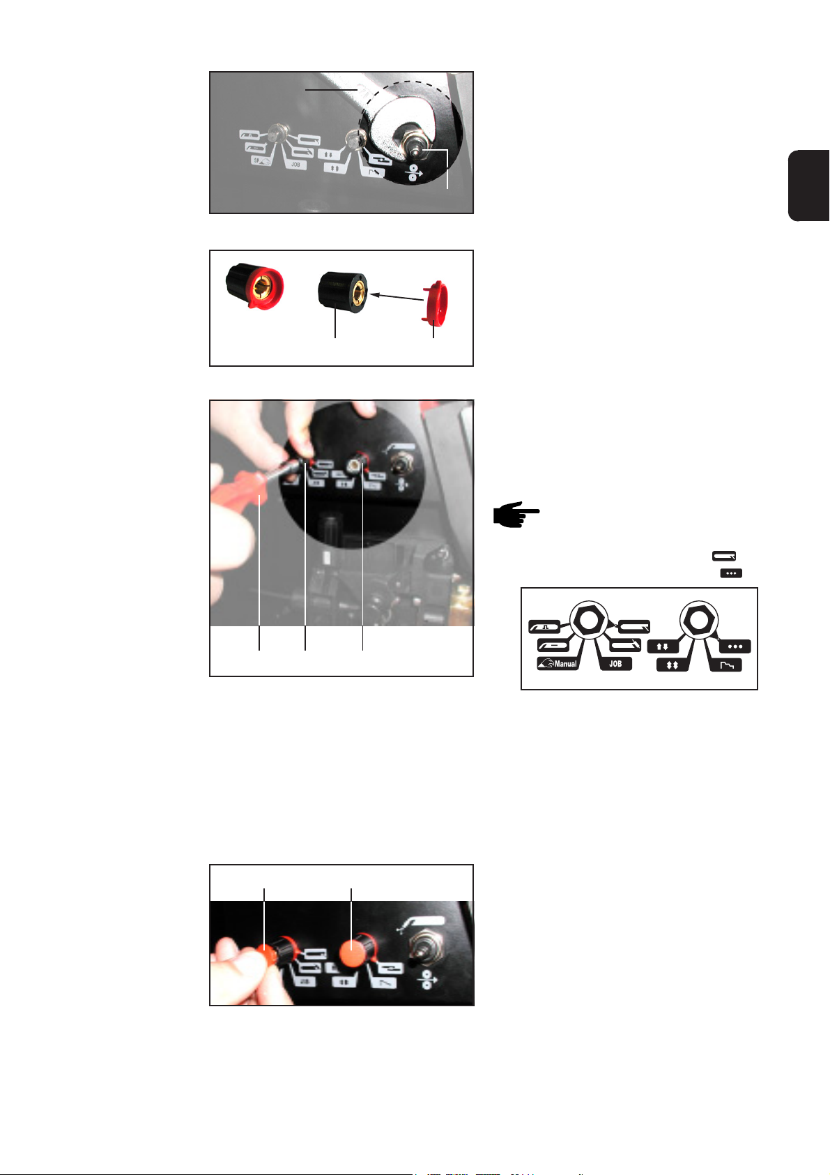
(B) (6)(6)
Abb.34 Rundmuttern aufschrauben
(D)
3. Rundmuttern (6) auf WahlschalterGewinde aufschrauben
4. Rundmuttern mittels Rundmutternschlüssel 13 mm (C) festziehen
5. Dichtung chrom (7) auf TasterGewinde aufschrauben
6. Dichtung chrom (7) mittels Gabelschlüssel SW17 (D) festziehen
(7)
Abb.35 Dichtung chrom aufschrauben
Abb.36 Drehknopf zusammenstecken
7. 2 x Drehknopf (3) und Mutterabdekkung (4) zusammenstecken
(4)(3)
13
Betriebswahlschalter einbauen
(Fortsetzung)
8. Wahlschalter mittels Kombizange (H)
bis zum Anschlag nach links drehen
9. Drehknopf mit Mutterabdeckung (3+4)
auf Wahlschalter aufstecken
Hinweis! Die Pfeilspitze der
Mutterabdeckung soll auf folgende Symbole zeigen:
- linker Wahlschalter auf
- rechter Wahlschalter auf
(B)
Abb.37a Drehknöpfe befestigen
(3+4) (3+4)
(5)(5)
Abb.37b Pfeilspitzen und Symbole
10. Drehknöpfe befestigen:
- Drehknöpfe mit Mutterabdeckung
(3+4) festhalten
- mittels Steckschlüssel SW7 (B)
festziehen
- Kontrolle, ob beim Drehen der
Drehknöpfe die Pfeilspitzen auf die
entsprechenden Symbole zeigen
11. 2 x Drehknopfdeckel (5) in Drehknopf
einsetzen
12. Flachbandkabel (2) am Print SR 41
anstecken:
- Flachbandkabel (2) seitlich beim
Print vorbei führen
- Flachbandkabel (2) am Stecker
RS485 (X2) anstecken
Abb.38 Drehknopfdeckel einsetzen
(2) (X2)
Abb.39 Flachbandkabel am Print anstecken
14

Abschließende
Tätigkeiten
Abb.40 Bedienpanel wieder einsetzen
(A)
13. Vorschub-Bedienpanel vorsichtig von
außen nach innen einsetzen
DE
Wichtig! Das Bedienpanel muß mit einem
„KLICK“ im Vorschub-Gehäuse einrasten.
1. Gehäuse (a) aufsetzen
2. Extrude-Tite-Schrauben auf Vorschub-Oberseite und Vorschub-Seite
mittels Handschraubendreher TX25
(A) einschrauben
3. Seitenteil links (b) schlließen
Abb.41 Gehäuse aufsetzen
(b)
(a)
15

Bohrschablonen
Allgemeines
Bohrschablone
VR 4000
Ab Seriennummer 13110550 sind die Drahtvorschübe VR 4000 und VR 7000 serienmäßig mit Bohrungen für den nachträglichen Einbau des Betriebswahlschalters ausgestattet.
Bei älteren Drahtvorschüben müssen die Bohrungen vor Einbau des Betriebswahlschalter am Drahtvorschub angebracht werden. Für die richtigen Abstände der Bohrungen
die entsprechenden Bohrschablonen verwenden.
Drahtvorschub Vorderfront
Oberkante Motorplatte
16

Bohrschablone
VR 7000
DE
Drahtvorschub Vorderfront
Oberkante Motorplatte
17

18

Dear Reader
Introduction
Thank you for choosing Fronius - and congratulations on your new, technically highgrade Fronius product! This instruction manual will help you get to know your new
machine. Read the manual carefully and you will soon be familiar with all the many
great features of your new Fronius product. This really is the best way to get the most
out of all the advantages that your machine has to offer.
Please also take special note of the safety rules - and observe them! In this way, you
will help to ensure more safety at your product location. And of course, if you treat your
product carefully, this definitely helps to prolong its enduring quality and reliability - things
which are both essential prerequisites for getting outstanding results.
EN
ud_fr_st_et_00493 01/2012


Contents
General remarks ........................................................................................................................................... 2
General remarks ...................................................................................................................................... 2
Software required..................................................................................................................................... 2
Components............................................................................................................................................. 2
Tools and equipment required ................................................................................................................. 3
Installing the mode selector switch in the VR 2000 wirefeeder .................................................................... 4
Preparatory work on the wirefeeder ......................................................................................................... 4
Preparatory work on the mode selector ................................................................................................... 4
Mounting the mode selector .................................................................................................................... 6
Finishing the job ....................................................................................................................................... 8
Installing the mode selector switch in the VR 4000 and VR 7000 wirefeeders............................................. 9
Preparatory work on the wirefeeder ......................................................................................................... 9
Preparatory work on the mode selector .................................................................................................. 11
Mounting the mode selector .................................................................................................................. 12
Finishing the job ..................................................................................................................................... 15
Drilling templates ........................................................................................................................................ 16
General remarks .................................................................................................................................... 16
VR 4000 drilling template ....................................................................................................................... 16
VR 7000 drilling template ....................................................................................................................... 17
EN
1

General remarks
General remarks
Software required
Components
The optional “Mode selector VR 2000” installation kit is used for retrofitting the
wirefeeders VR 2000, VR 4000 and VR 7000 with a mode selector switch.
Note! If the wirefeeder is equipped with a TR 4000 C operating panel, the
optional mode selector cannot be used.
Warning! Work that is not carried out correctly can cause serious injury and
damage. The actions described below may ONLY be carried out by skilled,
Fronius-trained personnel! Observe the safety regulations in the Operating
Instructions of the power source.
Before opening up the unit:
- shift the mains switch of the power source to the “O” position
- unplug the power source from the mains
- undo all connections between the wirefeeder and the power source
- disconnect the welding torch
In order to operate the optional “Mode selector”, the following firmware must be
installed in the power source: Firmware OFFICIAL UST V2.80.1
The “Mode selector” installation kit (4,100,360) consists of the following components:
(1)(9) (8) (7)(6) (5) (4)(3) (2)
Fig.1 “Mode selector” installation kit
(1) Printed circuit board, FPWS 1.................... 1 unit ...................................... 4,070,790
(2) Ribbon cable, 10-pole, 260 mm ................. 1 unit ................................ 43,0004,2142
(3) Rotary knobs, black ................................... 2 units...............................42,0406,0099
(4) Nut covers, red........................................... 2 units...............................42,0406,0213
(5) Rotary-knob covers, red............................. 2 units...............................42,0406,0109
(6) Round nuts M10x1, D=13x3 ...................... 2 units ............................... 42,0400,0115
(7) Washer, chrome ......................................... 1 unit ................................ 42,0406,0224
(8) ESD pouch, 152x254 mm, pink ................. 1 unit ................................ 40,0001,0404
(9) Cable binders, 150 ..................................... 2 units ............................... 42,0407,0100
(10) “Mode selector” adhesive label .................. 1 unit ................................ 42,0409,2894
(11) Installation instructions (not illustrated)...... 1 unit ................................ 42,0410,0856
2
(10)
Tools and equipment required
TX25
(A) Hand-held screwdriver TX25
(A)
(B) Socket spanner, width across = 7 mm
13 mm
Width = 7 mm
Width = 17 mm
Width = 14 mm
(C)
(G)
(B)
(I)
(H)
(F)
(E)
(D)
(K)
(J)
(M)
(N)
(C) Round-nut spanner, diam. = 13 mm
(D) Fork spanner, width across = 17 mm
EN
(E) Fork spanner, width across = 14 mm
(F) Side-cutting pliers
(G) Stanley knife
(H) Combination pliers
(I) Straight-bladed screwdriver
(J) Centre-punch
(K) Hammer
(L) Drill
(M) Metal drill bit, diam. 11 mm
(N) Metal drill bit, diam. 12.5 mm
Important! Tools (K) - (N) are only
needed for wirefeeders that are not
already provided with holes for the
optional mode selector switch.
Fig.2 Tools required
(L)
3

Installing the mode selector switch in the VR 2000
wirefeeder
Preparatory work
on the wirefeeder
(A)
(b)
(a)
Fig.3 Taking off the housing
(c)
1. Open the left side panel (b)
2. Using the hand-held screwdriver
TX25 (A), unscrew the Extrude-Tite
screws on the top and at the side of
the wirefeeder unit
3. Lift off the housing (a)
4. Remove the blanking covers (c)
The blanking covers are no longer
needed.
Preparatory work
on the mode
selector
Fig.4 Removing the blanking covers
5. Using the n° 14 fork spanner (E),
remove the hexagonal nuts from the
selector switches and the pushbutton
Important! Only remove the top
hexagonal nut from the pushbutton;
the bottom hexagonal nut and the
washer remain on the pushbutton.
The hexagonal nuts are no longer
needed.
(E)
Fig.5 Removing the hexagonal nuts
4
Preparatory work
on the mode
selector
(continued)
Fig.6 Making the cuts in the ESD pouch
Fig.7 Pushing down the film
(G)
(8)
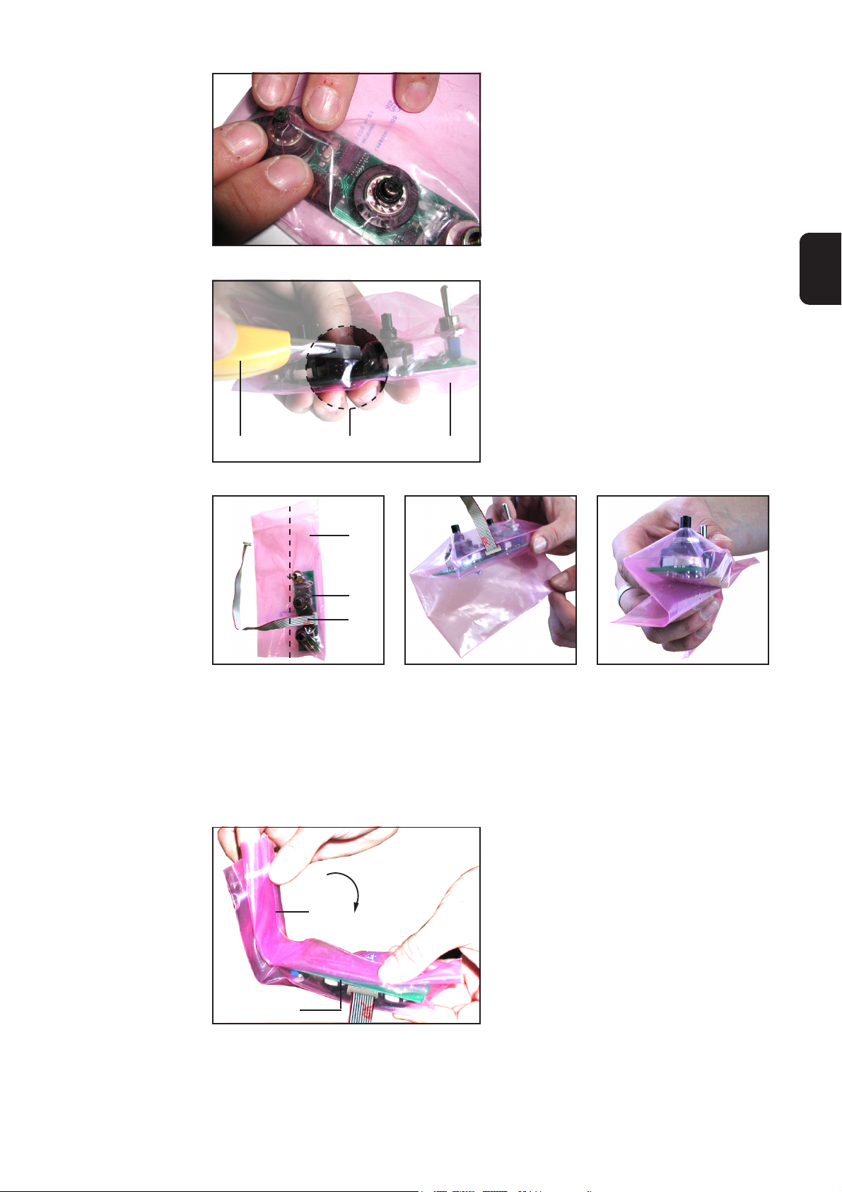
6. Put the FPWS 1 p.c.-board (1) in the
ESD pouch (8) - to protect it against
dust and moisture
EN
7. Using the Stanley knife (G), make
cross-shaped cuts in the ESD pouch
(8) above the selector switches and
the pushbutton
8. Push down the plastic film of the ESD
pouch so as to expose the selector
switches and the pushbutton as far
as the thread
(d)
Fig.8 Cutting out a hole to expose the connector
for the ribbon cable
(8)(G)
(8)
(1)
(2)
Fig.9a Plugging on the ribbon
cable
Fig.9b Folding the ESD pouch
around the board ...
9. Using the Stanley knife (G), cut a hole
out of the ESD pouch (8) to expose
the connector for the ribbon cable (d)
Fig.9c ... in the shape of an “S”
10. From outside the ESD pouch (8), plug the ribbon cable (2) onto the p.c.-board (1)
as shown in Fig. 9a
11. Fold the ESD pouch (8) along the side of the board and then in an S-shaped
pattern around the board (1), so that the bottom fold of the “S” runs along the
centre-line of the underside of the board
5

Preparatory work
on the mode
selector
(continued)
(8)
(1)
Fig.10 Folding the ESD pouch
(8)(9)
(9) (1)
Fig.11 Fixing the ESD pouch onto the board
12. Fold the projecting end of the ESD
pouch (8) along the end of the board
and then under the board (1)
13. Fix the ESD pouch (8) onto the board
(1) with the aid of cable binders (9)
14. Use the side-cutting pliers (F) to cut
the cable binders (9) to length
Mounting the
mode selector
Fig.12a Inserting the board into the wirefeeder
(6)
(6)
1. Insert the board into the wirefeeder:
- Ribbon cable on top
- Selector switches and pushbutton
into the holes provided
Fig.12b Close-up: Position of ribbon cable
2. Screw the round nuts (6) onto the
threads of the selector switches
3. Tighten the round nuts with the
round-nut spanner, diam. 13 mm (C)
(B)
Fig.13 Screwing on the round nuts
6
Mounting the
mode selector
(continued)
(D)
4. Screw the chrome washer (7) onto
the thread of the pushbutton
5. Tighten the chrome washer (7) with
the n° 14 fork spanner (D)
Fig.14 Screwing on the chrome washer
Fig.15 Fitting the rotary knob together
(7)
EN
6. Fit a nut cover (4) into each of the
rotary knobs (3)
(4)(3)
7. Use the combination pliers (H) to turn
each selector switch anticlockwise as
far as it will go
8. Push the rotary knob + nut cover
(3+4) onto the selector switch
Note! The tip of the arrow on the
nut cover should be pointing to
the following symbols:
- left selector switch: to
- right selector switch: to
(B)
(3+4) (3+4)
Fig.16a Fastening the rotary knobs in place
(5)(5)
Fig.17 Inserting the rotary-knob covers
Fig.16b Arrow pointers and symbols
9. Fasten the rotary knobs in place:
- Hold the rotary knob + nut cover
(3+4) firmly
- Tighten using the n° 7 socket
spanner (B)
- Check whether the tips of the
arrows point to the correct
symbols when you turn the knobs
10. Insert a rotary-knob cover (5) into
each of the knobs
7

Mounting the
mode selector
(continued)
(X2) (2)
Fig.18 Plugging the ribbon cable onto the board
(e)
11. Plug the ribbon cable (2) onto the SR
41 p.c.-board:
- Place the ribbon cable (2) in
recess (e)
- Plug the ribbon cable (2) onto the
RS485 connector (X2)
Finishing the job
(A)
(b)
(a)
Fig.19 Replacing the housing
1. Put the housing (a) back on
When replacing the housing, make
sure that:
- the ribbon cable is not trapped
- the ribbon cable is in recess (e)
2. Using the hand-held screwdriver
TX25 (A), screw the Extrude-Tite
screws into the top and the side of
the wirefeeder unit
3. Close the left side panel (b)
8

Installing the mode selector switch in the VR 4000
and VR 7000 wirefeeders
Preparatory work
on the wirefeeder
(A)
Fig.20 Taking off the housing
(b)
(a)
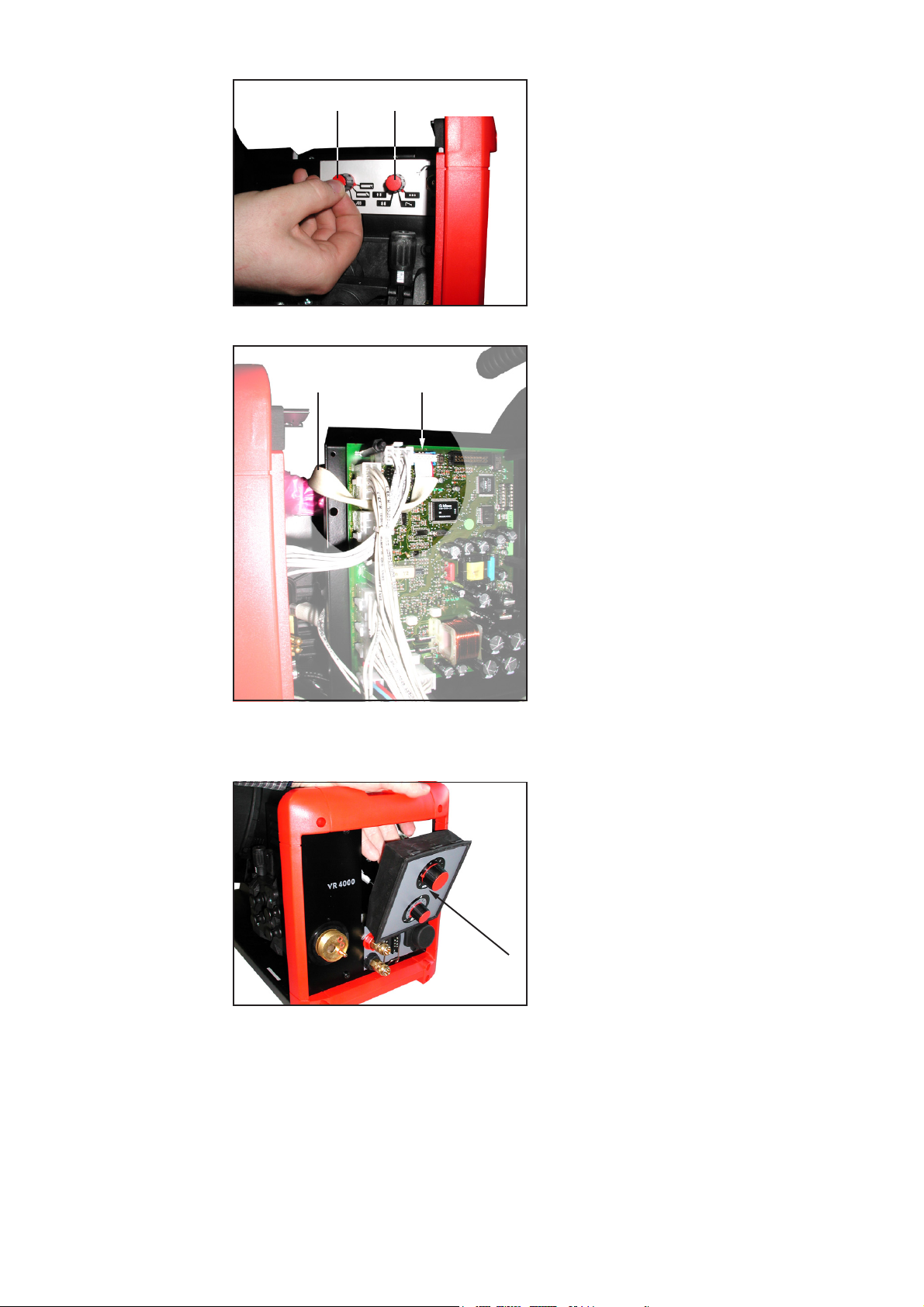
1. Open the left side panel (b)
2. Using the hand-held screwdriver
TX25 (A), unscrew the Extrude-Tite
screws on the top and at the side of
the wirefeeder unit
3. Lift off the housing (a)
4. Working from the inside of the wirefeeder towards the outside, carefully
press out the wirefeeder operating
panel
EN
Fig.21 Pressing out the operating panel
9

Preparatory work
on the wirefeeder
(continued)
(c)
4. Remove the blanking covers (c)
The blanking covers are no longer
needed.
Fig.22 Removing the blanking covers
If there are no drilled holes and blanking covers already provided on the wirefeeder,
make the holes needed for the mode selector switch as described below:
- Cut out the drilling template
- Position the drilling template as shown in the illustration below:
- Bottom edge of the drilling template along the top of the motor plate
- Right edge of the drilling template on the side of the front panel of the wirefeeder
- Use the hammer (K) and the centre-punch (J) to mark the position of the holes to
be drilled
- Remove the drilling template
- Using the metal bit (M) and the electric drill (L), drill two holes of 11 mm diameter
- Using the metal bit (N) and the electric drill (L), drill one hole of 12.5 mm diameter
Drilling template Drilling template
Fig.23 Position of the drilling template on the
VR 4000
Fig.24 Position of the drilling template on the
VR 7000
10

Preparatory work
on the mode
selector
(E)
Fig.25 Removing the hexagonal nuts
(G)
(8)
6. Using the n° 14 fork spanner (E),
remove the hexagonal nuts from the
selector switches and the pushbutton
Important! Only remove the top
hexagonal nut from the pushbutton;
the bottom hexagonal nut and the
washer remain on the pushbutton.
The hexagonal nuts are no longer
needed.
7. Put the FPWS 1 p.c.-board (1) in the
ESD pouch (8) - to protect it against
dust and moisture
EN
Fig.26 Making the cuts in the ESD pouch
Fig.27 Pushing down the film
8. Using the Stanley knife (G), make
cross-shaped cuts in the ESD pouch
(8) above the selector switches and
the pushbutton
9. Push down the plastic film of the ESD
pouch so as to expose the selector
switches and the pushbutton as far
as the thread
10. Using the Stanley knife (G), cut a hole
out of the ESD pouch (8) to expose
the connector for the ribbon cable (d)
(d)
Fig.28 Cutting out a hole to expose the connector
for the ribbon cable
(8)(G)
11

Preparatory work
on the mode
selector
(continued)
(8)
(1)
(2)
Fig.29a Plugging on the ribbon
cable
Fig.29b Folding the ESD pouch
around the board ...
Fig.29c ... in the shape of an “S”
11. From outside the ESD pouch (8), plug the ribbon cable (2) onto the p.c.-board (1)
as shown in Fig. 29a
12. Fold the ESD pouch (8) along the side of the board and then in an S-shaped
pattern around the board (1), so that the bottom fold of the “S” runs along the
centre-line of the underside of the board
13. Fold the projecting end of the ESD
pouch (8) along the end of the board
and then under the board (1)
(8)
(1)
Fig.30 Folding the ESD pouch
14. Fix the ESD pouch (8) onto the board
(1) with the aid of cable binders (9)
15. Use the side-cutting pliers (F) to cut
the cable binders (9) to length
Mounting the
mode selector
(8)(9) (9) (1)
Fig.31 Fixing the ESD pouch onto the board
(10)
Fig.32 Affixing the adhesive label
12
1. Affix the “Mode selector” adhesive
label (10)
Important! Affix the adhesive label in
such a way that the punched-out
areas are positioned exactly above
the drilled holes.

Mounting the
mode selector
(continued)
2. Insert the board into the wirefeeder:
- Ribbon cable on top
- Selector switches and pushbutton
into the holes provided
EN
Fig.33a Inserting the board into the wirefeeder
Fig.33b Close-up: Position of ribbon cable
(B) (6)(6)
Fig.34 Screwing on the round nuts
(D)
3. Screw the round nuts (6) onto the
threads of the selector switches
4. Tighten the round nuts with the
round-nut spanner, diam. 13 mm (C)
5. Screw the chrome washer (7) onto
the thread of the pushbutton
6. Tighten the chrome washer (7) with
the n° 14 fork spanner (D)
(7)
Fig.35 Screwing on the chrome washer
Fig.36 Fitting the rotary knob together
7. Fit a nut cover (4) into each of the
rotary knobs (3)
(4)(3)
13

(B) (3+4) (3+4)
Fig.37a Fastening the rotary knobs in place
8. Use the combination pliers (H) to turn
each selector switch anticlockwise as
far as it will go
9. Push the rotary knob + nut cover
(3+4) onto the selector switch
Note! The tip of the arrow on the
nut cover should be pointing to
the following symbols:
- left selector switch: to
- right selector switch: to
Fig.37b Arrow pointers and symbols
10. Fasten the rotary knobs in place:
- Hold the rotary knob + nut cover
(3+4) firmly
- Tighten using the n° 7 socket
spanner (B)
- Check whether the tips of the
arrows point to the correct
symbols when you turn the knobs
(5)(5)
Fig.38 Inserting the rotary-knob covers
(2) (X2)
11. Insert a rotary-knob cover (5) into
each of the knobs
12. Plug the ribbon cable (2) onto the SR
41 p.c.-board:
- Guide the ribbon cable (2) past the
side of the board
- Plug the ribbon cable (2) onto the
RS485 connector (X2)
Fig.39 Plugging the ribbon cable onto the board
14
Finishing the job
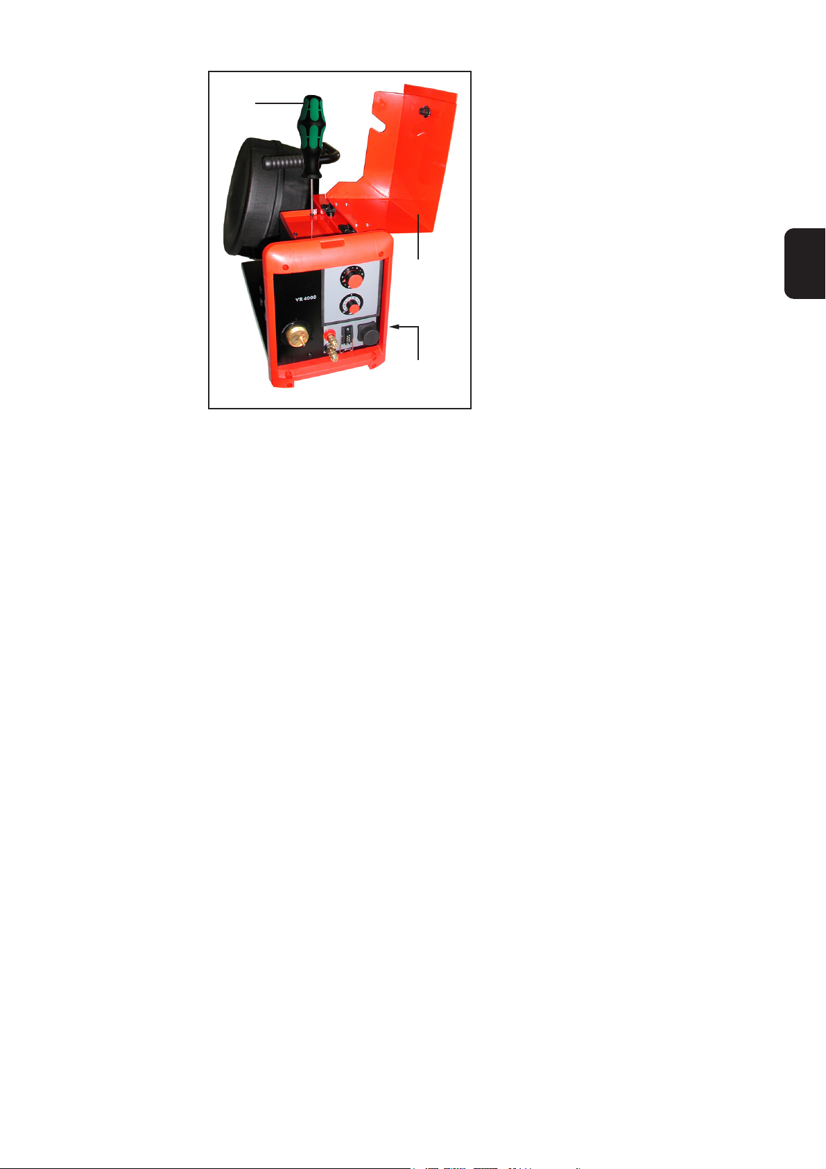
Fig.40 Fitting the operating panel back in
(A)
13. Working from the outside towards the
inside, carefully fit the wirefeeder
operating panel back in
Important! The operating panel must
snap back into the housing of the
wirefeeder with an audible “CLICK”.
EN
1. Put the housing (a) back on
2. Using the hand-held screwdriver
TX25 (A), screw the Extrude-Tite
screws into the top and the side of
the wirefeeder unit
3. Close the left side panel (b)
Fig.41 Replacing the housing
(b)
(a)
15

Drilling templates
General remarks
VR 4000 drilling
template
From serial number 13110550 upwards, the VR 4000 and VR 7000 wirefeeders are
provided - as a series feature - with ready-drilled holes for retrofitting the mode selector
switch.
Before the mode selector switch can be retrofitted to older wirefeeders, however, the
necessary holes have to be drilled first. In order to ensure that these holes are drilled in
the right places, and the right distances apart, use the appropriate drilling template.
Front panel of wirefeeder
Top edge of motor plate
16
VR 7000 drilling
template
EN
Top edge of motor plate
Front panel of wirefeeder
17

18

Cher lecteur
Introduction
Nous vous remercions de votre confiance et vous félicitons d’avoir acheté un produit de
qualité supérieure de Fronius. Les instructions suivantes vous aideront à vous familiariser avec le produit. En lisant attentivement les instructions de service suivantes, vous
découvrirez les multiples possibilités de votre produit Fronius. C’est la seule manière
d’exploiter ses avantages de manière optimale.
Prière d’observer également les consignes de sécurité pour garantir une sécurité accrue
lors de l’utilisation du produit. Une utilisation soigneuse du produit contribue à sa longévité et sa fiabilité. Ce sont des conditions essentielles pour obtenir d’excellents résultats.
FR
ud_fr_st_et_00500 01/2012


Table de Contents
Généralités.................................................................................................................................................... 2
Généralités............................................................................................................................................... 2
Logiciel requis .......................................................................................................................................... 2
Composants ............................................................................................................................................. 2
Outils et auxiliaires requis ........................................................................................................................ 3
Montage du set de montage commutateur de sélection de mode de service dans le déroulement du fil-
électrode VR 2000 ........................................................................................................................................ 4
Préparatifs au déroulement du fil-électrode ............................................................................................. 4
Préparatifs au commutateur de sélection de mode de service ................................................................ 4
Montage du commutateur de sélection de mode de service ................................................................... 6
Mesures finales ........................................................................................................................................ 8
Montage du set de montage commutateur de sélection de mode de service dans le déroulement du fil-
électrode VR 4000 et VR 7000 ..................................................................................................................... 9
Préparatifs au déroulement du fil-électrode ............................................................................................. 9
Préparatifs au commutateur de sélection de mode de service .............................................................. 10
Montage du commutateur de sélection de mode de service ................................................................. 12
Mesures finales ...................................................................................................................................... 14
Gabarits de perçage ................................................................................................................................... 16
Généralités............................................................................................................................................. 16
Gabarit de perçage VR 4000 ................................................................................................................. 16
Gabarit de perçage VR 7000 ................................................................................................................. 17
FR
1

Généralités
Généralités
Logiciel requis
L’option set de montage commutateur de sélection de mode de service sert à
l’équipement ultérieur du déroulement du fil-électrode VR 2000, VR 4000 et VR 7000
avec le commutateur de sélection de mode de service.
Remarque! Si le déroulement est muni du panneau de commande TR 4000,
l’option commutateur de sélection de mode de service ne peut pas être utilisée.
Avertissement! Les travaux effectués de manière incorrecte peuvent causer de
graves dommages matériels et corporels. Les activités décrites ci-après ne
doivent être effectuées que par un membre du personnel formé par Fronius!
Respecter les consignes de sécurité dans la notice d’utilisation de votre source
de courant.
Avant l’ouverture de l’appareil:
- Mettre l’interrupteur d’alimentation de la source de courant en position «O»
- Tirer la fiche secteur de la source de courant
- Séparer les liaisons entre le déroulement et la source de courant
- Fermer le chalumeau soudeur
Pour le fonctionnement du commutateur de sélection de mode de service, le micrologiciel
suivant est nécessaire sur la source de courant: micrologiciel OFFICIAL UST V2.80.1
Composants
Le set de montage commutateur de sélection de mode de service VR 2000 (4,100, 360)
est composé des éléments suivants:
(7)
(1)(9) (8)
Fig.1 Set de montage commutateur de sélection de mode de service
(1) Plaquette à circuits imprimés FPWS 1...................... 1 pce ....................... 4,070,790
(2) Câble plat 260 mm .................................................... 1 pce ................. 43,0004,2142
(3) Bouton rotatif noir...................................................... 2 pces. .............. 42,0406,0099
(4) Recouvrement d’écrou rouge.................................... 2 pces. .............. 42,0406,0213
(5) Couvercle de bouton rotatif rouge............................. 2 pces. .............. 42,0406,0109
(6) Ecrou rond M10x1, D=13x3 ...................................... 2 pces. .............. 42,0400,0115
(7) Joint en chrome ........................................................ 1 pce. ................ 42,0406,0224
(8) Sachet ESD 152x254 mm, rose................................ 1 pce. ................ 40,0001,0404
(9) Ligature de câble 150 ............................................... 2 pces. .............. 42,0407,0100
(10) Commutateur de sélection de mode de service ........ 1 pce. ................ 42,0409,2894
(11) Instructions de montage (sans ill.) ............................ 1 pce. ................ 42,0410,0856
(6) (5)
(10)
(4)(3) (2)
2

Outils et auxiliaires requis
TX25
(A) Tournevis X25
(A)
(B) Clé à canon de 7
13 mm
CP7
OC17
OC14
(C)
(G)
(B)
(I)
(H)
(F)
(E)
(D)
(K)
(C) Clé à écrou rond 13 mm
(D) Clé à fourche de17
(E) Clé à fourchel de 14
(F) Pince diagonale
(G) Cutter
(H) Pince universelle
(I) Tournevis
(J) Pointeau
(K) Marteau
(L) Perceuse
(M) Mèche à métal de 11 mm de diamètre
(N) Mèche à métal de 12,5 mm de
diamètre
FR
Fig.2 Outillage nécessaire
(J)
(M)
(N)
(L)
Important! Les outils (K)-(N) ne sont
requis que pour les déroulements de filélectrode ne comportant pas encore de
perçages pour l’option commutateur de
sélection de mode de service.
3
Montage du set de montage commutateur de sélection de mode de service dans le déroulement du filélectrode VR 2000
Préparatifs au
déroulement du
fil-électrode
(A)
(b)
(a)
Fig.3 Retirer le boîtier
1. Ouvrir la partie latérale gauche (b)
2. Dévisser les vis Extrude-Tite sur le
dessus et le côté du déroulement à
l’aide du tournevis TX25 (A)
3. Retirer le boîtier en le soulevant
4. Retirer les recouvrements borgnes (c)
(c)
On n’a plus besoin des recouvrements borgnes
Préparatifs au
commutateur de
sélection de
mode de service
Fig.4 Retirer les recouvrements borgnes
5. Retirer les écrous des commutateurs
de sélection et du bouton-poussoir au
moyen d’une clé à fourche SW14 (E).
Remarque: ne retirer que l’écrou
hexagonal supérieur du boutonpoussoir, l’écrou hexagonal inférieur
et le disque restent sur le boutonpoussoir
On n’a plus besoin des écrous hégagonaux
(E)
Fig. 5 Retirer les écrous hexagonaux
4

Préparatifs au
commutateur de
sélection de
mode de service
(suite)
(G)
(8)
Fig. 6 Découper une croix sur le sachet ESD
6. Metre la plaquette à circuits imprimés
FPWS 1 (1) dans le sachet ESD (8) pour le protéger de l’humidité et de la
poussière.
7. A l’aide du cutter, découper le sachet
ESD (8) en croix au-dessus des
commutateurs de sélection et du
bouton-poussoir.
8. Presser la feuille du sachet vers le
bas de manière à ce que le commutateur de sélection et le boutonpoussoir soient dégagés jusqu’au
filetage
FR
Fig. 7 Presser la feuille de sachet
Fig. 8 Découper une ouverture
(8)
(1)
(2)
9. Découper une ouverture pour la fiche
destinée au câble plat (d) au moyen
du cutter (G) dans le sachet ESD
(8)(G) (d)
Fig. 9a Brancher le câble plat Fig. 9b Plier le sachet ESD
autour de la plaquette à
circuits imprimés
Fig. 9c ... en forme de S
10. Brancher le câble plat (2) de l’extérieur du sachet ESD (8) suivant la figure 9a sur
la plaquette à circuits imprimés
11. Plier le sachet ESD (8) le long de la partie longitudinale de la plaquette (1) en forme
de S, de manière à ce que l’arête extérieure du sachet se trouve à la hauteur du
centre de la plaquette.
5

Préparatifs au
commutateur de
sélection de
mode de service
(suite)
12. Rabattre l’extrémité qui dépasse du
sachet ESD (8) le long de la partie
frontale de la plaquette sous la
plaquette (1)
(8)
(1)
Fig.10 Plier le sachet ESD
13. Fixer le sachet ESD (8) au moyen de
la ligature de câble sur la plaquette
14. Raccourcir la ligature de câble (9) au
moyen de la pince diagonale
Montage du
commutateur de
sélection de
mode de service
(9)
Fig.11 Fixer le sachet ESD sur la plaquette
Fig. 12a Placer la plaquette dans le déroulement
(9)(8)
(1)
1. Insérer la plaquette dans le déroule-
ment:
- Câble plat en haut
- Commutateur de sélection ou
bouton-poussoir dans les alésages
prévus
Fig. 12b Détail de la position du câble plat
(6)
(6)
(B)
Fig. 13 Visser les écrous ronds
2. Visser les écrous ronds (6) sur le
filetage du commutateur de sélection
3. Serrer les écrous ronds à l’aide d’une
clé à écrous ronds de 13 mm (C)
6

Montage du
commutateur de
sélection de
mode de service
(suite)
(D)
Fig. 14 Visser le joint en chrome
4. Visser le joint en chrome (7) sur le
filetage du bouton-poussoir
5. Serrer le joint en chrome (7) au
moyen d’une clé à fourche SW 14 (D)
(7)
Fig. 15 Assembler le bouton rotatif
6. Assembler le bouton rotatif (3) et le
recouvrement d’écrou (4) deux fois.
FR
(4)(3)
7. Tourner le commutateur de sélection
vers la gauche jusqu’à la butée à
l’aide d’une pince universelle (H)
8. Placer le bouton rotatif avec le recouvrement d’écrou (3+4) sur le commutateur de sélection
Remarque: la pointe de la flèche
du recouvrement d’écrou doit être
dirigée vers les symboles suivants:
- commutateur de gauche sur
- commutateur de droite sur
(B)
(3+4) (3+4)
Fig. 16a Fixer les boutons rotatifs
(5)(5)
Fig. 16 Pointes de flèche et symboles
9. Fixer les boutons rotatifs:
- Maintenir les boutons rotatifs avec
le recouvrement d’écrou (3+4)
- serrer à l’aide de la clé à canon
SW 7 (B)
- Vérifier si les pointes des flèches
sont dirigées vers les symboles
correspondants en tournant les
boutons rotatifs.
10. Placer les couvercles de bouton
rotatifs (5) sur les boutons rotatifs, 2
fois.
Fig. 17 Placer le couvercle de bouton rotatif
7

Montage du
commutateur de
sélection de
mode de service
(suite)
(X2) (2)
Fig.18 Brancher le câble plat à la fiche
(e)
11. Brancher le câble plat (2) sur la
plaquette SR 41:
- Mettre le câble plat (2) dans
l’encoche (e)
- Brancher le câble plat (2) à la
fiche RS485 (X2)
Mesures finales
(A)
(b)
(a)
Fig. 19 Mise en place du boîtier
1. Mettre en place le boîtier
Pour cela, attention à ne pas
- Coincer le câble plat
- Le câble plat doit être dans
l’encoche (e)
2. Visser les vis Extrude-Tite sur la
partie supérieure et le côté du déroulement à l’aide d’un tournevis TX 25
(A)
3. Fermer la partie latérale à gauche (b)
8

Montage du set de montage commutateur de sélection de mode de service dans le déroulement du filélectrode VR 4000 et VR 7000
Préparatifs au
déroulement du
fil-électrode
(A)
Fig.20 Retirer le boîtier
(b)
(a)
1. Ouvrir la partie latérale gauche (b)
2. Dévisser les vis Extrude-Tite sur le
dessus et le côté du déroulement à
l’aide du tournevis TX25 (A)
3. Retirer le boîtier en le soulevant
4. Presser prudement le panneau de
commande du déroulement du filélectrode de l’intérieur vers
l’extérieur
FR
Fig.21 Presser le panneau de commande à
l’extérieur
(c)
Fig.22 Retirer les recouvrements borgnes
4. Retirer les recouvrements borgnes (c)
On n’a plus besoin des recouvrements borgnes
9
Préparatifs au
déroulement du
fil-électrode
(suite)
En l’absence de perçages et de recouvrements borgnes au déroulement du fil-électrode,
faire les perçages pour le commutateur de sélection de mode de service comme suit:
- Découper le gabarit de perçage
- Placer le gabarit de perçage comme la figure l’indique:
- Arête inférieure du gabarit de perçage sur l’arête supérieure de la plaque du
moteur
- Arête droite du gabarit de perçage sur la partie frontale du déroulement
- Marquer la position des perçages au moyen du marteau (K) et du pointeau (J)
- Retirer le gabarit de perçage
- Faire 2 perçages d’un diamètre de 11 mm au moyen de la méche à métal et de la
perceuse.
- Faire 1 perçage d’un diamètre de 12,5 mm au moyen de la mèche à métal (N) et de
la perceuse (L)
Gabarit de perçcage Gabarit de perçage
Préparatifs au
commutateur de
sélection de
mode de service
Fig.23 Position du gabarit de perçage au VR 4000 Fig.24 Position du gabarit de perçage au VR 7000
6. Retirer les écrous des commutateurs
de sélection et du bouton-poussoir au
moyen d’une clé à fourche SW14 (E).
Important! ne retirer que l’écrou
hexagonal supérieur du boutonpoussoir, l’écrou hexagonal inférieur
et le disque restent sur le boutonpoussoir
On n’a plus besoin des écrous hégagonaux
(E)
Fig.25 Retirer les écrous hexagonaux
7. Metre la plaquette à circuits imprimés
(G)
FPWS 1 (1) dans le sachet ESD (8) pour le protéger de l’humidité et de la
poussière.
(8)
Fig.26 Découper une croix sur le sachet ESD
10
8. A l’aide du cutter, découper le sachet
ESD (8) en croix au-dessus des
commutateurs de sélection et du
bouton-poussoir.
Préparatifs au
commutateur de
sélection de
mode de service
(suite)
9. Presser la feuille du sachet vers le
bas de manière à ce que le commutateur de sélection et le boutonpoussoir soient dégagés jusqu’au
filetage
Fig.27 Presser la feuille de sachet
FR
10. Découper une ouverture pour la fiche
destinée au câble plat (d) au moyen
du cutter (G) dans le sachet ESD
(8)(G) (d)
Fig.28 Découper une ouverture
(8)
(1)
(2)
Fig.29a Brancher le câble plat
Fig.29b Plier le sachet ESD
autour de la plaquette à
circuits imprimés
Fig.29c ... en forme de S
11. Brancher le câble plat (2) de l’extérieur du sachet ESD (8) suivant la figure 9a sur
la plaquette à circuits imprimés
12. Plier le sachet ESD (8) le long de la partie longitudinale de la plaquette (1) en forme
de S, de manière à ce que l’arête extérieure du sachet se trouve à la hauteur du
centre de la plaquette.
13. Rabattre l’extrémité qui dépasse du
sachet ESD (8) le long de la partie
frontale de la plaquette sous la
plaquette (1)
(8)
(1)
Fig.30 Plier le sachet ESD
11

Préparatifs au
commutateur de
sélection de
mode de service
(suite)
14. Fixer le sachet ESD (8) au moyen de
la ligature de câble sur la plaquette
15. Raccourcir la ligature de câble (9) au
moyen de la pince diagonale
Montage du
commutateur de
sélection de
mode de service
(9)
Fig.31 Fixer le sachet ESD sur la plaquette
(9)(8)
(10)
Fig.32 Coller l’autocollant
(1)
1. Coller l’autocollant commutateur de
sélection de mode de service (10)
Important! Coller l’autocollant de
manière à positionner exactement les
surfaces découpées au-dessus des
perçages
2. Insérer la plaquette dans le déroulement:
- Câble plat en haut
- Commutateur de sélection ou
bouton-poussoir dans les alésages
prévus
Fig. 33a Placer la plaquette dans le déroulement
12
Fig. 33b Détail de la position du câble plat

Montage du
commutateur de
sélection de
mode de service
(suite)
(B) (6)(6)
Fig.34 Visser les écrous ronds
3. Visser les écrous ronds (6) sur le
filetage du commutateur de sélection
4. Serrer les écrous ronds à l’aide d’une
clé à écrous ronds de 13 mm (C)
FR
(D)
Fig. 35 Visser le joint en chrome
Fig.36 Assembler le bouton rotatif
5. Visser le joint en chrome (7) sur le
filetage du bouton-poussoir
6. Serrer le joint en chrome (7) au
moyen d’une clé à fourche SW 14 (D)
(7)
7. Assembler le bouton rotatif (3) et le
recouvrement d’écrou (4) deux fois.
(4)(3)
8. Tourner le commutateur de sélection
vers la gauche jusqu’à la butée à
l’aide d’une pince universelle (H)
9. Placer le bouton rotatif avec le recouvrement d’écrou (3+4) sur le commutateur de sélection
(B) (3+4) (3+4)
Fig.37a Fixer les boutons rotatifs
Fig.37b Pointes de flèche et symboles
Remarque! La pointe de la
flèche du recouvrement d’écrou
doit être dirigée vers les symboles suivants:
- commutateur de gauche sur
- commutateur de droite sur
10. Fixer les boutons rotatifs:
- Maintenir les boutons rotatifs avec
le recouvrement d’écrou (3+4)
- serrer à l’aide de la clé à canon
SW 7 (B)
- Vérifier si les pointes des flèches
sont dirigées vers les symboles
correspondants en tournant les
boutons rotatifs.
13
Montage du
commutateur de
sélection de
mode de service
(suite)
(5)(5)
Fig.38 Placer le couvercle de bouton rotatif
(2) (X2)
11. Placer les couvercles de bouton
rotatifs (5) sur les boutons rotatifs, 2
fois.
12. Brancher le câble plat (2) sur la
plaquette SR 41:
- Faire passer le câble plat (2) sur le
côté de la plaquette à circuits
imprimés
- Brancher le câble plat (2) à la
fiche RS485 (X2)
Mesures finales
Fig.39 Brancher le câble plat à la fiche
13. Insérer prudemment le panneau de
commande du déroulement du filélectrode de l’extérieur vers l’intérieur
Important! Le panneau de commande
doit s’enclencher avec un «Clic» audible
dans le boîtier du déroulement du filélectrode.
Fig.40 Insérer le panneau de commande
14
Mesures finales
(suite)
(A)
1. Mettre en place le boîtier
Pour cela, attention à ne pas
2. Visser les vis Extrude-Tite sur la
partie supérieure et le côté du déroulement à l’aide d’un tournevis TX 25
(A)
3. Fermer la partie latérale à gauche (b)
Fig.41 Mise en place du boîtier
(b)
(a)
FR
15

Gabarits de perçage
Généralités
Gabarit de perçage VR 4000
A partir du numéro de série 13110550, les déroulements du fil-électrode VR 4000 et VR
7000 sont munis de perçages en série en vue du montage ultérieur du commutateur de
sélection du mode de service.
Pour les déroulements plus anciens, les perçages doivent être effectués sur le déroulement avant le montage du commutateur de sélection de mode de service. Utiliser les
gabarits de perçage pour avoir les bons écarts entre les perçages.
Partie frontale déroulement
Arête supérieure
plaque du moteur
16

Gabarit de perçage VR 7000
déroulement
Partie frontale
FR
Arête supérieure
plaque du moteur
17

FRONIUS INTERNATIONAL GMBH
Froniusplatz 1, A-4600 Wels, Austria
Tel: +43 (0)7242 241-0, Fax: +43 (0)7242 241-3940
E-Mail: sales@fronius.com
www.fronius.com
Under http://www.fronius.com/addresses you will find all addresses
www.fronius.com/addresses
of our Sales & service partners and Locations.
ud_fr_st_so_00082 012011
 Loading...