


/ Battery Charging Systems / Welding Technology / Solar Electronics
EN
Robacta TX options
Operating Instructions
System extension
42,0426,0109,EN 010-12082013

0

Dear reader,
Introduction Thank you for the trust you have placed in our company and congratulations on buying this
high-quality Fronius product. These instructions will help you familiarise yourself with the
product. Reading the instructions carefully will enable you to learn about the many different
features it has to offer. This will allow you to make full use of its advantages.
Please also note the safety rules to ensure greater safety when using the product. Careful
handling of the product will repay you with years of safe and reliable operation. These are
essential prerequisites for excellent results.
EN
1

2

Contents
Robacta TX cover 7
Safety......................................................................................................................................................... 9
Safety.................................................................................................................................................... 9
General ...................................................................................................................................................... 10
Device concept ..................................................................................................................................... 10
Scope of supply .................................................................................................................................... 10
Tools required ....................................................................................................................................... 10
Fitting the Robacta TX cover ..................................................................................................................... 11
Preparation ........................................................................................................................................... 11
Fitting the Robacta TX cover ................................................................................................................ 13
And finally... .......................................................................................................................................... 14
Locking the Robacta TX cover................................................................................................................... 15
Locking the cover.................................................................................................................................. 15
Robacta TX W with Robacta TX cover program sequence ....................................................................... 16
Safety.................................................................................................................................................... 16
General ................................................................................................................................................. 16
Speed data for the program sequence ................................................................................................. 16
Subprograms in the program sequence................................................................................................ 16
Program sequence................................................................................................................................ 17
Servicing the Robacta TX cover ................................................................................................................ 25
Weekly .................................................................................................................................................. 25
Yearly or after 30,000 torch neck changeover cycles ........................................................................... 25
EN
Pneumatic Robacta TX cover 29
Safety......................................................................................................................................................... 31
Safety.................................................................................................................................................... 31
General ...................................................................................................................................................... 32
Device concept ..................................................................................................................................... 32
Scope of supply .................................................................................................................................... 32
Tools required ....................................................................................................................................... 32
Commissioning the pneumatic Robacta TX cover ..................................................................................... 33
Preparation ........................................................................................................................................... 33
Fitting one pneumatic Robacta TX cover.............................................................................................. 34
Installing one pneumatic Robacta TX cover ......................................................................................... 35
Fitting two pneumatic Robacta TX covers ............................................................................................ 37
Installing two pneumatic Robacta TX covers ........................................................................................ 38
Checking the function of the pneumatic Robacta TX cover .................................................................. 39
Locking the pneumatic Robacta TX cover ................................................................................................. 41
Locking the cover.................................................................................................................................. 41
Robacta TX slide, Robacta TX slide XL 43
Safety......................................................................................................................................................... 45
Safety.................................................................................................................................................... 45
Fitting the Robacta TX slide....................................................................................................................... 46
Preparation ........................................................................................................................................... 46
Safety.................................................................................................................................................... 46
Fit the slide............................................................................................................................................ 46
And finally... .......................................................................................................................................... 47
Fitting the Robacta TX slide XL ................................................................................................................. 48
Preparation ........................................................................................................................................... 48
Safety.................................................................................................................................................... 48
Screw base to the underlying surface................................................................................................... 48
Fit the XL slide ...................................................................................................................................... 49
Fit the standard slide to the XL base .................................................................................................... 49
And finally... .......................................................................................................................................... 49
Commissioning the Robacta TX slide / Robacta TX slide XL .................................................................... 50
3

Placing a torch neck in the Robacta TX slide / Robacta TX slide XL.................................................... 50
Changing the program sequence to account for the Robacta TX slide / Robacta TX slide XL............. 50
Robacta TX W torch neck rack 53
Safety......................................................................................................................................................... 55
Safety.................................................................................................................................................... 55
Fitting a torch neck rack piece ................................................................................................................... 56
Scope of supply .................................................................................................................................... 56
Preparation ........................................................................................................................................... 56
Safety.................................................................................................................................................... 56
Fitting a torch neck rack piece .............................................................................................................. 56
And finally... .......................................................................................................................................... 57
Robacta TX G torch neck rack 59
Safety......................................................................................................................................................... 61
Safety.................................................................................................................................................... 61
Fitting a torch neck rack piece ................................................................................................................... 62
Scope of supply .................................................................................................................................... 62
Preparation ........................................................................................................................................... 62
Safety.................................................................................................................................................... 62
Fitting a torch neck rack piece .............................................................................................................. 62
And finally... .......................................................................................................................................... 63
Torch neck coding 65
Safety......................................................................................................................................................... 67
Safety.................................................................................................................................................... 67
Coding the torch neck ................................................................................................................................ 68
General ................................................................................................................................................. 68
Preparation ........................................................................................................................................... 68
Safety.................................................................................................................................................... 68
Coding the torch neck ........................................................................................................................... 69
And finally... .......................................................................................................................................... 70
Compressed air maintenance unit 71
Safety......................................................................................................................................................... 73
Safety.................................................................................................................................................... 73
General ...................................................................................................................................................... 74
General ................................................................................................................................................. 74
Scope of supply .................................................................................................................................... 74
Tools required ....................................................................................................................................... 74
Fitting the compressed air maintenance unit ............................................................................................. 75
Preparation ........................................................................................................................................... 75
Safety.................................................................................................................................................... 75
Fitting the compressed air maintenance unit ........................................................................................ 75
And finally... .......................................................................................................................................... 77
Wire cutter 79
Safety......................................................................................................................................................... 81
Safety.................................................................................................................................................... 81
Installing the wire cutter ............................................................................................................................. 82
Preparation ........................................................................................................................................... 82
Safety.................................................................................................................................................... 82
Installing the wire cutter ........................................................................................................................ 82
And finally... .......................................................................................................................................... 83
Welding torch cleaning devices 85
Safety......................................................................................................................................................... 87
Safety.................................................................................................................................................... 87
4

Installing the Robacta TC 1000.................................................................................................................. 88
General ................................................................................................................................................. 88
Preparation ........................................................................................................................................... 88
Safety.................................................................................................................................................... 88
Fitting the wire cutter............................................................................................................................. 88
Installing the welding torch cleaning device.......................................................................................... 89
And finally... .......................................................................................................................................... 89
Installing the Robacta Reamer V Easy, Robacta Reamer aluminium brush head..................................... 90
General ................................................................................................................................................. 90
Preparation ........................................................................................................................................... 90
Safety.................................................................................................................................................... 90
Installing the welding torch cleaning device.......................................................................................... 90
And finally... .......................................................................................................................................... 91
Installing the Robacta Reamer V ............................................................................................................... 92
Preparation ........................................................................................................................................... 92
Safety.................................................................................................................................................... 92
Installing the welding torch cleaning device.......................................................................................... 92
And finally... .......................................................................................................................................... 93
Mounting bracket for a TCP measurement unit 95
Safety......................................................................................................................................................... 97
Safety.................................................................................................................................................... 97
Mounting bracket for advintec standard ..................................................................................................... 98
Preparation ........................................................................................................................................... 98
Safety.................................................................................................................................................... 98
Fitting the mounting bracket.................................................................................................................. 98
And finally... .......................................................................................................................................... 99
Mounting bracket for advintec adjustable .................................................................................................. 100
Preparation ........................................................................................................................................... 100
Safety.................................................................................................................................................... 100
Fitting the mounting bracket.................................................................................................................. 100
And finally... .......................................................................................................................................... 101
EN
5

6

Robacta TX cover

Safety
Safety Observe the following safety rules for all work described in the "Robacta TX cover" section.
WARNING! Incorrect operation or shoddy workmanship can cause serious injury
or damage. All activities described in these operating instructions may only be
carried out by trained and qualified personnel. All functions described in these operating instructions may only be used by trained and qualified personnel. Do not
carry out any of the work or use any of the functions described until you have fully
read and understood the following documents:
- these operating instructions
- all the operating instructions for the system components, especially the safety rules
WARNING! Machines that start up automatically can cause serious injury and
damage. In addition to these operating instructions, the safety rules issued by the
manufacturers of the robot and welding systems must also be observed. For your
personal safety, ensure that all protective measures have been taken and will remain in place while you are in the working area of the robot.
WARNING! Risk of severe injury from the robot arm. Ensure there is no one else
within the working area of the robot whenever work is carried out.
EN
WARNING! Work that is carried out incorrectly can cause serious injury or dam-
age. Before starting work:
- turn the power source mains switch to the "O" position
- disconnect the power source from the mains
- put up an easy-to-understand warning sign to stop anybody inadvertently
switching it back on again
CAUTION! Risk of injury from sharp flying parts. During the work described below, always wear the following protective equipment:
- protective goggles with side protection
- ear protection
- gloves - electrically insulated and providing protection against heat
CAUTION! Risk of burns from hot torch neck, hot torch neck coupling and other
hot welding torch components. Before carrying out work, allow the torch neck,
torch neck coupling and all other welding torch components to cool down to room
temperature (+25 °C, +77 °F).
9

General
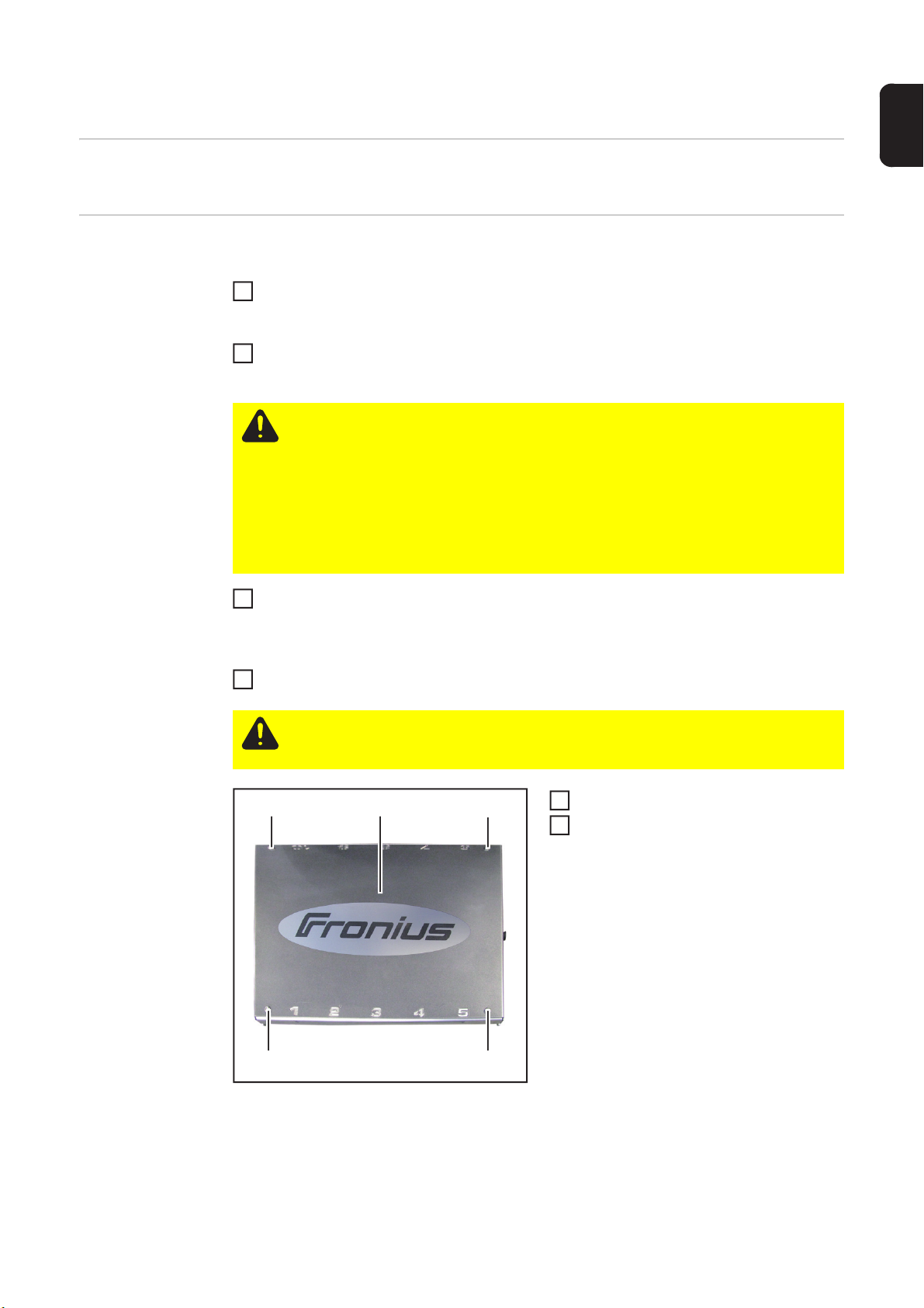
Device concept The Robacta TX cover shields all the torch neck rack pieces on the torch neck changeover
station. To facilitate work on the torch neck rack pieces, the cover can be fixed in place by
a locking bolt. An integral sensor monitors the position of the cover.
Scope of supply
(1)
(2)
(3)
(1) Robacta TX cover
(2) Wire sensor fitting panel
(3) 2x M5 x 16 mm Allen screws
(4) 4x A5 washers
(5) 2x M5 self-locking hexagonal nuts
(6) 4x M10 hexagon bolts with 1.25
fine-pitch thread
Tools required - TX 25 Torx screwdriver
- Box spanner, size 17
- Box spanner, size 8
- 8 mm Allen key
- 4 mm Allen key
- 2.5 mm Allen key
(4)
(5)
(6)
10

Fitting the Robacta TX cover
1
(1)
Preparation Depressurise the compressed air line of the torch neck changeover station and ensure
that this compressed air line remains depressurised for the duration of the work on the
device
Disconnect the compressed air line from compressed air connection "A" on the torch
2
neck changeover station
CAUTION! Risk of injury from escaping compressed air from compressed air
connection "A". Compressed air emerges at up to 16 bar (232.06 psi) from compressed air connection "A" when the Unlock/Lock button is pressed. While compressed air is emerging from compressed air connection "A":
- wear ear protection
- keep the face and all other body parts away from compressed air connection
"A"
- ensure that no other persons are in the vicinity of the torch neck changeover
station
Press and hold the Unlock/Lock button on the torch neck changeover station until
3
compressed air no longer emerges from compressed air connection "A" on the torch
neck changeover station
- compressed-air booster unit in the torch neck changeover station discharges
De-energise the torch neck changeover station
4
EN
CAUTION! Risk of injury from compressed air escaping unintentionally. The torch
neck changeover station must remain depressurised and de-energised until all
work is completed.
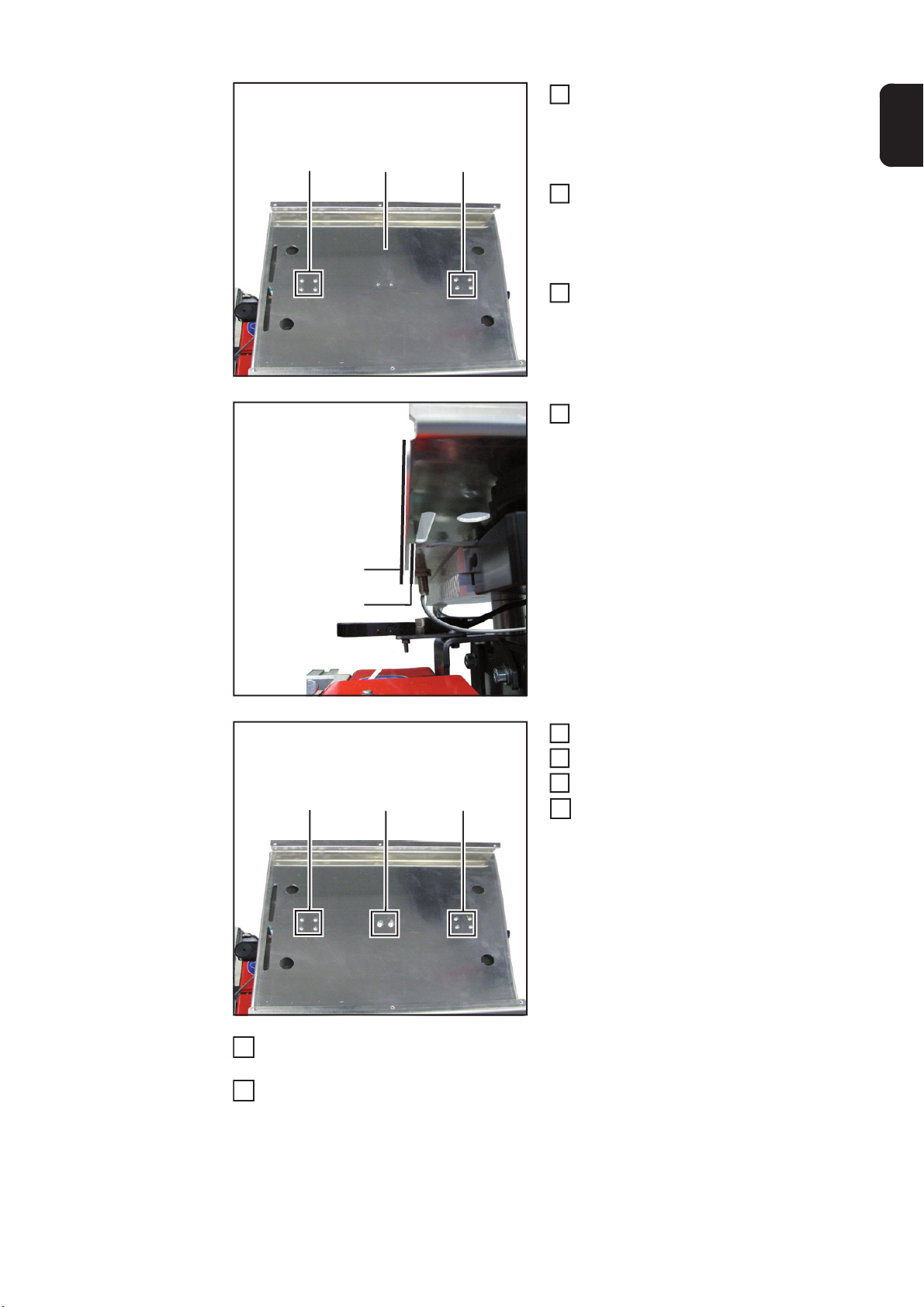
Undo screws (1)
5
Keep screws, nuts and washers for la-
6
ter use
11
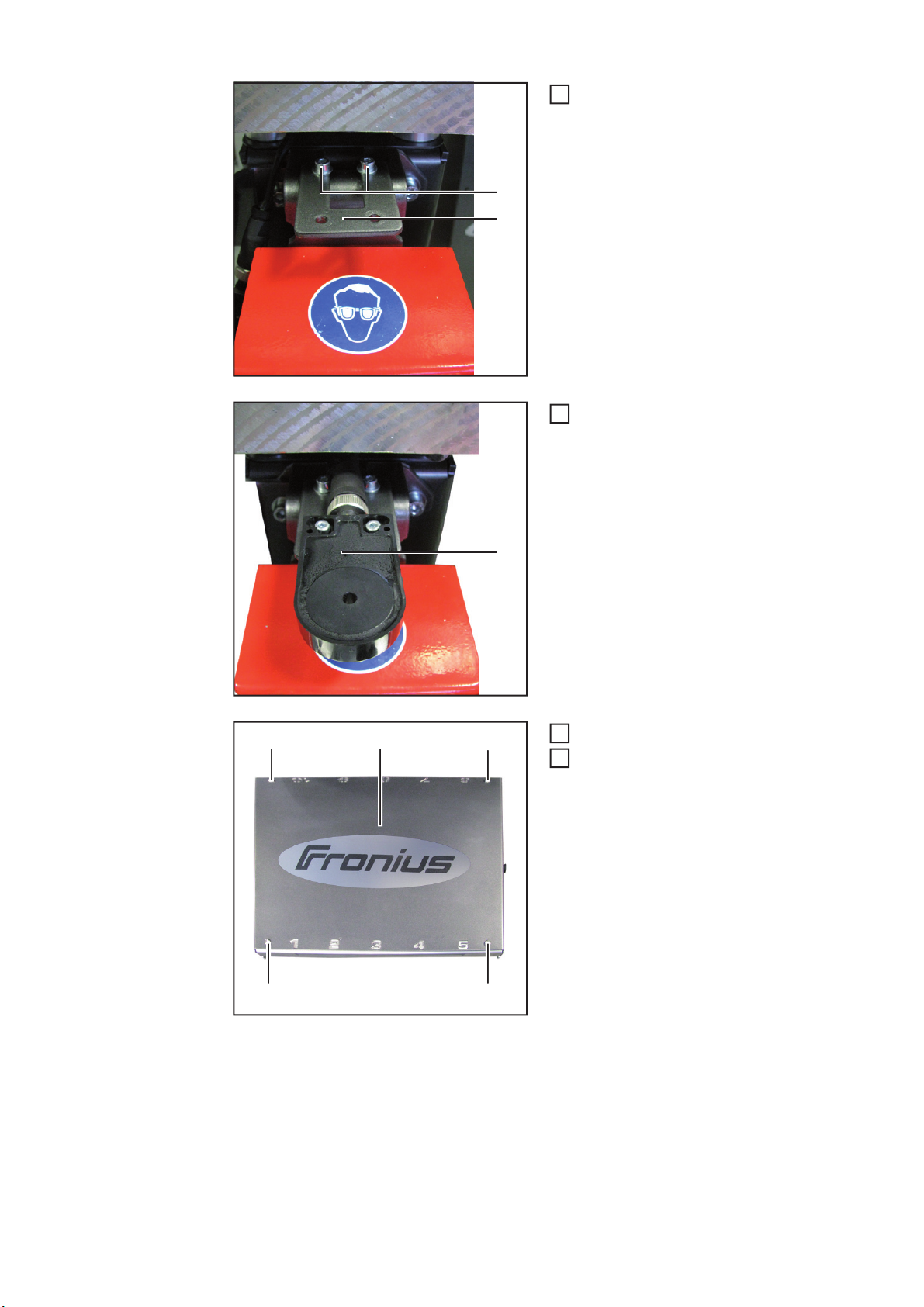
Fit the wire sensor mounting plate (2)
(3)
(2)
7
as shown, using
- 2x M5 x 16 mm screws (3)
- 4x A5 washers
- 2x M5 self-locking hexagonal nuts
Secure the wire sensor (4) to the wire
8
sensor mounting plate as shown
(5) (6)
(5)
(5)(5)
(4)
Undo screws (5)
9
Remove the cover lid (6)
10
12

Fitting the Robac-
(2)
(2)
(2)
(2)
(2)
(2)
(2)
(2)
(3)
2
ta TX cover
(1)
Undo the 8 screws (2)
1
Remove lid (3)
Place the cover onto the torch neck
3
changeover station in such a way that
the Robacta TX cover sensor (1) is on
the same side of the torch neck changeover station as the wire sensor
EN
Underside of cover
(3) (3)(2)
Insert four M10 screws into the holes
4
(3) and secure the cover in place
(3)(3)
13

(4) (5)
5
Guide the sensor cable (4) through the
5
housing opening (5)
Connect the sensor plug to connection
6
X14 on the PC board in the torch neck
changeover station
Fit the lid for the Robacta TX cover
7
onto the subframe of the Robacta TX
cover
Fit the torch neck changeover station
8
cover onto the torch neck changeover
station
And finally...
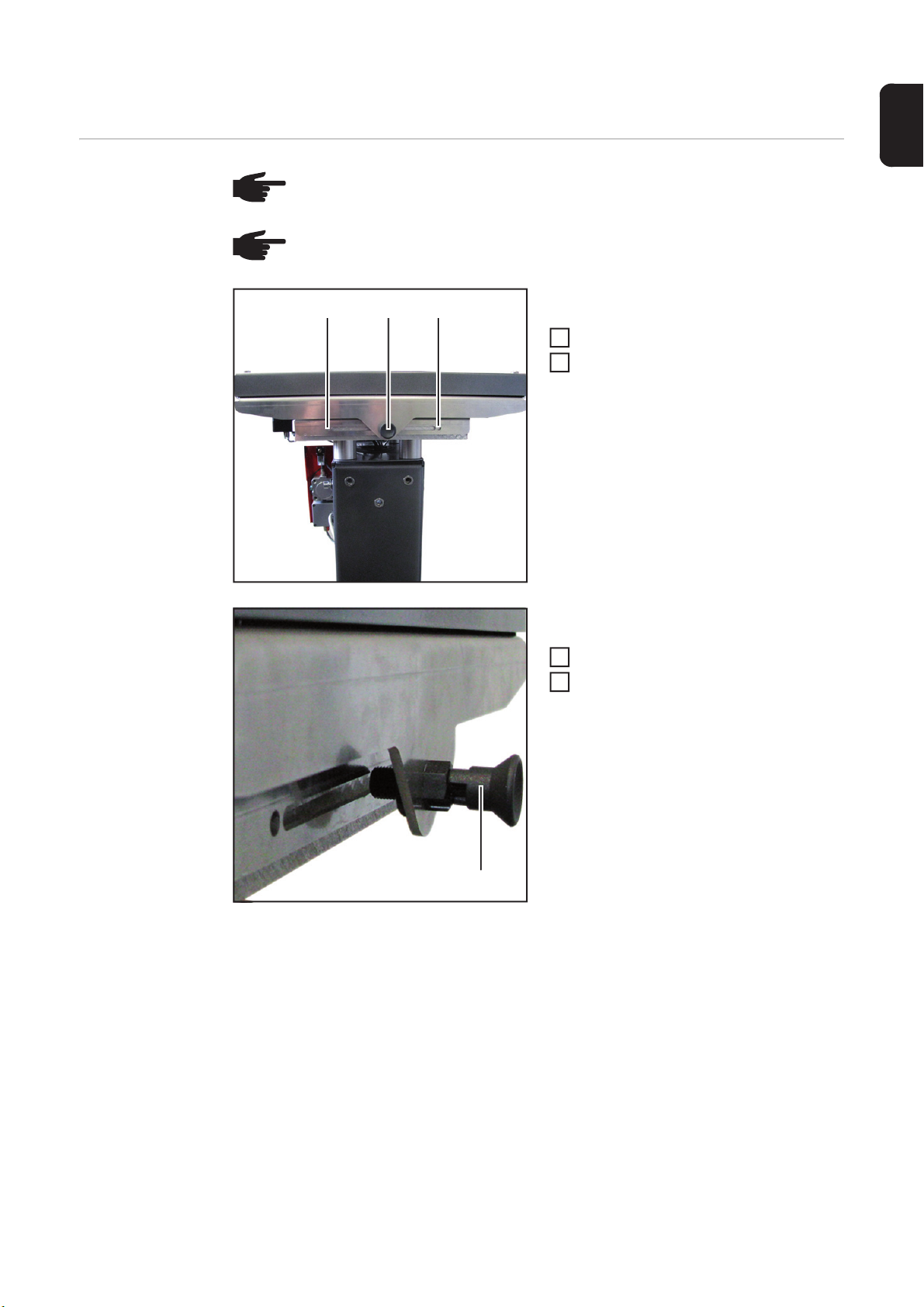
Attempt to move the cover back and
1
forth
- the cover must be easy to move
Establish the power supply to the torch
2
neck changeover station
When the cover is in a central position:
- the LED (1) on the base of the sensor
lights up
- a signal is sent to the robot control
When the cover is not in a central position:
- the LED (1) on the base of the sensor
does not light up
(1)
Connect the compressed air line to compressed air connection "A" on the torch neck
3
changeover station
Establish the compressed air supply to the torch neck changeover station
4
Change the position of the wire sensor in the robot program
NOTE! After fitting the cover, program the robot with the Robacta TX W with Robacta TX cover program sequence
- no signal is sent to the robot control
14
Locking the Robacta TX cover
1
2
EN
Locking the cover
NOTE! Do not lock the cover while the torch neck changeover station is in use.
NOTE! Ensure that the cover locking bolt remains in the operating position while
the torch neck changeover station is in use.
(2) (2)(1)
Lock the cover as follows
Push the cover to the desired side
Allow the locking bolt (1) to latch in the
2
respective locking hole (2)
(1)
To unlock, proceed as follows
Hold the cover
1
Remove the locking bolt (1) from the
locking hole and move to the position
shown
- the locking bolt is in the operating
position
15

Robacta TX W with Robacta TX cover program sequence
Safety
General
Speed data for
the program sequence
CAUTION! Risk of damage. Do not start in automatic mode until the torch neck
changeover station has been properly installed and started up.
NOTE! After fitting the cover, program the robot with the following program sequence.
A list of all speeds and corresponding units in the program sequence:
cm/min m/s ipm
1000 = 0.17 = 393.70
600 = 0.1 = 236.22
100 = 0.017 = 39.37
70 = 0.012 = 27.56
50 = 0.008 = 19.69
35 = 0.006 = 13.78
30 = 0.005 = 11.81
Subprograms in
the program sequence
To facilitate programming, the program sequence is split into the following subprograms:
- Cut wire electrode
- Wind back wire electrode
- Set down torch neck
- Pick up torch neck
- Advance wire electrode
- Cut wire electrode
16
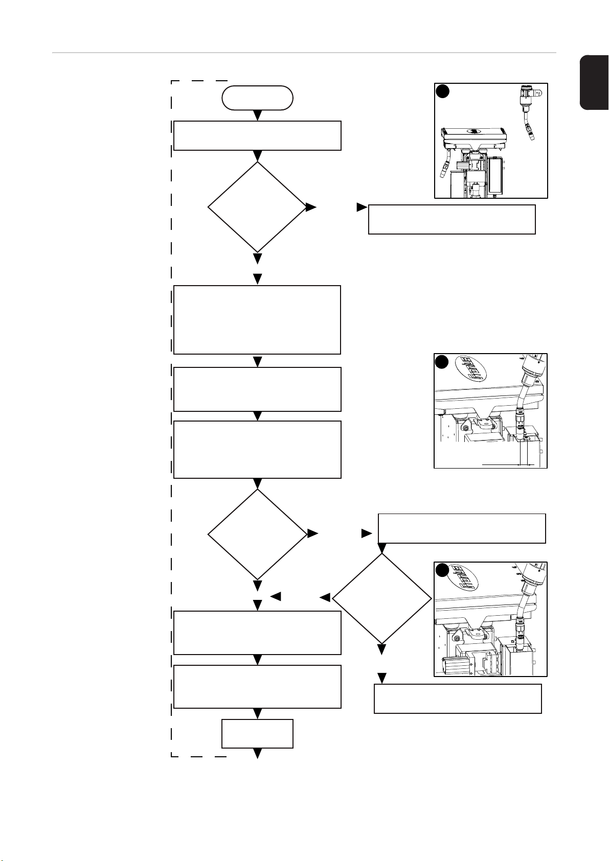
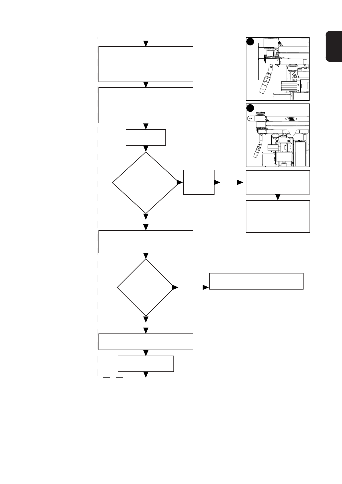
Program se-
Wait 0.5
seconds
Move to pos. A
- above torch neck rack
Program stop
- power source error
Reset
- wire cutter signal
Program stop
- wire cutter error
Move to pos. B
- approx. 25 mm (0.98 in.) next
to wire cutter
Set
- select job to advance
wire electrode
- wire threading speed:
600 cm/min (236.22 ipm)
Move to pos. C
- enter wire cutter
Set
- cut wire electrode signal
Set
- advance wire electrode signal
- duration of signal: 2 seconds
Start
Query
- power
source ready
Query
- wire
cutter open
Query
- wire
cutter open
'False'
'True'
'True'
'False'
'True'
'False'
Cut wire electrode
A
B
25 mm
0.98 in.
C
quence
EN
17

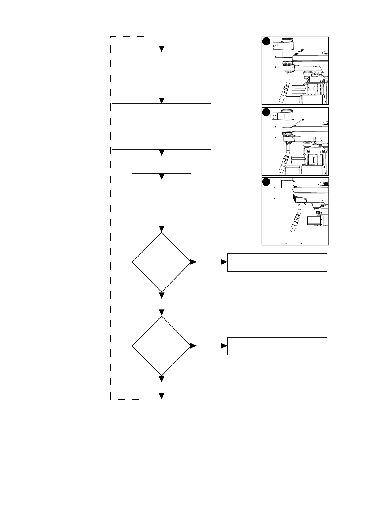
Query
- wire cutter
closed
'False'
Program stop
- wire cutter error
(continued)
Cut wire electrode
- cut wire electrode signal
- rewind wire electrode signal
- rewind wire electrode until
behind coupling point
Rewind wire electrode
- wire threading speed:
600 cm/min (236.22 ipm)
- duration of signal: calculated
using torch neck length
above rack positions
'True'
Reset
Move to pos. D
Query
- torch neck
sensor
Set
'True'
D
Program stop
- torch neck change error
'False'
Move to pos. E
- 70 mm (2.76 in.) next to middle
of torch neck rack
- 40 mm (1.57 in.) above top of
torch neck rack
Set down torch neck
Query
- Robacta TX
cover
'True'
'False'
E
40 mm
1.57 in.
70 mm
2.76 in.
Program stop
- torch neck change error
18
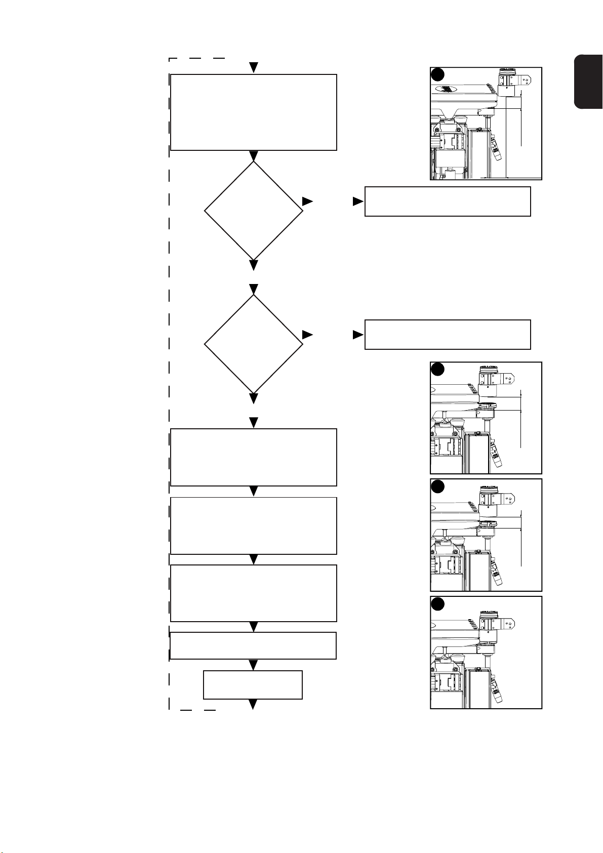
Move to pos. F
- move 40 mm (1.57 in.) above
middle of torch neck rack
- speed:
max. 100 cm/min (39.37 ipm)
Move to pos. G
- move down into torch neck
rack
- speed:
max. 50 cm/min (19.69 ipm)
Wait 0.5
seconds
Query
- torch neck
sensor (torch neck
picked up
flush)
Wait 5
seconds
'False'
F
40 mm
1.57 in.
G
Stop
- enter torch neck rack
EN
'True'
Stop
- enter torch neck rack
Set down torch neck (continued)
Query
- pressure switch
'True'
Set
- change torch neck signal
Wait 1.5
seconds
'False'
Program stop
- torch neck change
error
Program stop
- torch neck change error
19
Move to pos. H
- raise 15 mm (0.59 in.) above
middle of torch neck rack
- speed:
max. 30 cm/min (11.81 ipm)
H
15 mm
0.59 in.
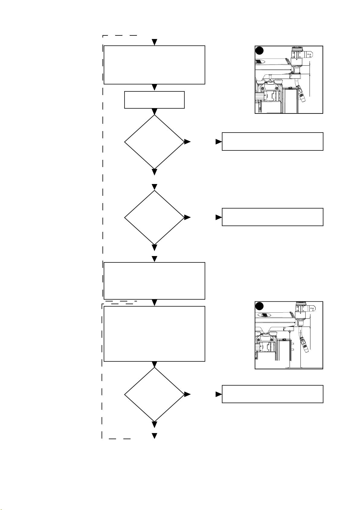
Move to pos. I
- raise 40 mm (1.57 in.) above
middle of torch neck rack
- speed: high
Wait 0.5
seconds
Move to pos. J
- 70 mm (2.76 in.) next to middle
of torch neck rack
- 40 mm (1.57 in.) above top of
torch neck rack
(continued)
Set down torch neck
Query
Robacta TX
cover
'False'
I
40 mm
1.57 in.
J
40 mm
1.57 in.
Program stop
- torch neck change error
70 mm
2.76 in.
'True'
Query
- torch neck
sensor
'False'
'True'
Program stop
- torch neck change error
20
Move to pos. K
- 70 mm (2.76 in.) next to middle
of torch neck rack
- 40 mm (1.57 in.) above top of
torch neck rack
K
EN
40 mm
1.57 in.
70 mm
2.76 in.
Query
- Robacta TX
cover
'True'
Query
- torch neck
sensor
'True'
Pick up torch neck
Move to pos. L
- 40 mm (1.57 in.) above middle
of torch neck to be picked up
'False'
'False'
Program stop
- torch neck change error
Program stop
- torch neck change error
L
40 mm
1.57 in.
Move to pos. M
- 15 mm (0.59 in.) above middle
of torch neck to be picked up
Move to pos. N
- pick up torch neck flush
max. 70 cm/min (27.56 ipm)
- change torch neck signal
- speed:
Reset
Wait 3 - 4
seconds
M
N
15 mm
0.59 in.
21
Move to pos. R
- raise 40 mm (1.57 in.) above
middle of torch neck rack
- speed: high
Wait 0.5
seconds
R
40 mm
1.57 in.
Query
- torch neck
sensor
'False'
Query
pressure switch
Pick up torch neck (continued)
- power source reset error (only if
using a flow sensor)
- 40 mm (1.57 in.) above top of
- 70 mm (2.76 in.) next to middle
1000 cm/min (393.70 ipm)
'True'
Set
Move to pos. S
torch neck rack
of torch neck rack
- speed: max.
Advance wire electrode
'True'
'False'
Program stop
- torch neck change error
Program stop
- torch neck change error
S
40 mm
70 mm
2.76 in.
1.57 in.
22
Query
- Robacta TX
cover
'True'
'False'
Program stop
- torch neck change error

Advance wire electrode (continued)
'True'
Cut wire electrode
Wait 15
seconds
Reset
- advance wire
electrode signal
Program stop
- torch neck change
error
Reset
- wire cutter signal
Program stop
- wire cutter error
Move to pos. Q
- align gas nozzle approx. 10 mm
(0.39 in.) centrally above wire
sensor
Set
- advance wire electrode signal
- wire threading speed:
600 cm/min (236.22 ipm)
Reset
- advance wire electrode signal
Move to pos. B
- approx. 25 mm (0.98 in.) next
to wire cutter
Set
- advance wire electrode signal
- duration of signal: 1 second
'False'
'True'
Query
- wire cutter
open
Query
- wire cutter
open
'False'
Query
wire sensor
'False'
'True'
Q
10 mm
0.39 in.
B
25 mm
0.98 in.
EN
23

Move to pos. C
- enter wire cutter
Set
- cut wire electrode signal
Reset
- cut wire electrode signal
Wait 0.5
seconds
Program stop
- wire cutter error
Query
- wire cutter
closed
'False'
'True'
Program stop
- torch neck change error
Query
- power source
ready
'False'
'True'
Cut wire electrode (continued)
End
C
24
Servicing the Robacta TX cover
2
(1) (2)
(1)
(1)(1)
Weekly Check the cover for damage
EN
Yearly or after
30,000 torch neck
changeover cycles
Clean and lubricate the profiled rail guides:
Depressurise the compressed air line of the torch neck changeover station and ensure
1
that this compressed air line remains depressurised for the duration of the work on the
device
Disconnect the compressed air line from compressed air connection "A" on the torch
neck changeover station
CAUTION! Risk of injury from escaping compressed air from compressed air
connection "A". Compressed air emerges at up to 16 bar (232.06 psi) from compressed air connection "A" when the Unlock/Lock button is pressed. While compressed air is emerging from compressed air connection "A":
- wear ear protection
- keep the face and all other body parts away from compressed air connection
"A"
- ensure that no other persons are in the vicinity of the torch neck changeover
station
Press and hold the Unlock/Lock button on the torch neck changeover station until
3
compressed air no longer emerges from compressed air connection "A" on the torch
neck changeover station
- compressed-air booster unit in the torch neck changeover station discharges
De-energise the torch neck changeover station
4
CAUTION! Risk of injury from compressed air escaping unintentionally. The torch
neck changeover station must remain depressurised and de-energised until all
work is completed.
Undo screws (1)
5
Remove the lid (2)
6
25

Undo screws (3) and (4)
8
(9)(9)
7
Remove cover plate (5)
(6)
(3) (4)
(7)
(5)
(8)
(3)
(6)
Clean the profiled rails (6)
9
Clean the centring spindle (7)
10
Clean the centring carriage (8)
11
11
Lubricate the profiled rails (6)
12
Move the trolleys (9) up and down the
13
profiled rails to distribute the lubricant
26
(10) (11)
(12)
(13)
17
(10) (14)
(10)
20
21
22
23
(10)
Screw in the eight screws with
14
washers (10), tighten slightly
- the cover plate (11) must still be
able to move on the profiled rail
trolleys
Move the cover plate as far as it will go
15
in one direction
- this aligns the cover plate and the
profiled rail trolleys with each
other
Once the trolleys and cover plate are
16
aligned, tighten the screws (10) to fix
the cover plate in this position
Check whether the edges (12) and (13)
are parallel to each other
- if not, undo the screws (10) and
align the cover plate again
EN
Tighten screws and washers (10)
18
Tighten screws and washers (14)
19
Fit the lid
Check the cover is functioning correctly
Connect the compressed air line to compressed air connection "A" on the torch neck
changeover station
Establish the compressed air and power supply to the torch neck changeover station
27

28

Pneumatic Robacta TX cover


Safety
Safety Observe the following safety rules for all work described in the "Pneumatic Robacta TX
cover" section.
WARNING! Incorrect operation or shoddy workmanship can cause serious injury
or damage. All activities described in these operating instructions may only be
carried out by trained and qualified personnel. All functions described in these operating instructions may only be used by trained and qualified personnel. Do not
carry out any of the work or use any of the functions described until you have fully
read and understood the following documents:
- these operating instructions
- all the operating instructions for the system components, especially the safety rules
WARNING! Machines that start up automatically can cause serious injury and
damage. In addition to these operating instructions, the safety rules issued by the
manufacturers of the robot and welding systems must also be observed. For your
personal safety, ensure that all protective measures have been taken and will remain in place while you are in the working area of the robot.
WARNING! Risk of severe injury from the robot arm. Ensure there is no one else
within the working area of the robot whenever work is carried out.
EN
WARNING! Work that is carried out incorrectly can cause serious injury or dam-
age. Before starting work:
- turn the power source mains switch to the "O" position
- disconnect the power source from the mains
- put up an easy-to-understand warning sign to stop anybody inadvertently
switching it back on again
CAUTION! Risk of injury from sharp flying parts. During the work described below, always wear the following protective equipment:
- protective goggles with side protection
- ear protection
- gloves - electrically insulated and providing protection against heat
CAUTION! Risk of burns from hot torch neck, hot torch neck coupling and other
hot welding torch components. Before carrying out work, allow the torch neck,
torch neck coupling and all other welding torch components to cool down to room
temperature (+25 °C, +77 °F).
31

General
(1)
Device concept The pneumatic Robacta TX cover shields up to five torch neck rack pieces on one side of
the torch neck changeover station rack holder. A signal from the robot control opens and
closes the cover. An integral sensor monitors the position of the cover. Two covers are
needed to shield both sides of the rack holder.
Scope of supply
(2)
(3)
(1) Pneumatic Robacta TX cover
(2) Compressed air line
(3) Compressed air distributor
Tools required - TX 25 Torx screwdriver
- 8 mm Allen key
32

Commissioning the pneumatic Robacta TX cover
1
Preparation Depressurise the compressed air line of the torch neck changeover station and ensure
that this compressed air line remains depressurised for the duration of the work on the
device
Disconnect the compressed air line from compressed air connection "A" on the torch
2
neck changeover station
CAUTION! Risk of injury from escaping compressed air from compressed air
connection "A". Compressed air emerges at up to 16 bar (232.06 psi) from compressed air connection "A" when the Unlock/Lock button is pressed. While compressed air is emerging from compressed air connection "A":
- wear ear protection
- keep the face and all other body parts away from compressed air connection
"A"
- ensure that no other persons are in the vicinity of the torch neck changeover
station
Press and hold the Unlock/Lock button on the torch neck changeover station until
3
compressed air no longer emerges from compressed air connection "A" on the torch
neck changeover station
- compressed-air booster unit in the torch neck changeover station discharges
De-energise the torch neck changeover station
4
EN
(3)
CAUTION! Risk of injury from compressed air escaping unintentionally. The torch
neck changeover station must remain depressurised and de-energised until all
work is completed.
Undo screws (3)
(3) (4)
(3)
(3)
5
Remove the cover lid (4)
6
33

(5)
8
2
(5)
Undo screws (5)
7
Remove lid (6)
Fitting one pneumatic Robacta TX
cover
(5)
(5)
(5)
(1)
(2)
(2)
(5)
(6)
(5)
(5)
(1)
Undo screws and washers (1) to fit the
1
cover, if required, for torch neck rack
pieces 1-5
Undo screws and washers (2) to fit the
cover, if required, for torch neck rack
pieces 6-10
- Keep the screws for later use
- The washers may be disposed of
(3)
(4)
Remove blanking plug (3) to fit the cover, if required, for torch neck rack pieces 1-5
Remove blanking plug (4) to fit the cover, if required, for torch neck rack pieces 6-10
- The blanking plugs may be disposed of
34

(7)
7
(5)
(7)
(6)
Open the cover
3
Place the cover on the holder retainer
4
as shown
Ensure that the edges of the cover (5)
5
and the holder retainer (6) are parallel
to each other
Close the cover
6
NOTE! Screw cover in place without washers.
Screw cover in place using the screws
(7) previously removed from the holder
retainer
EN
Installing one
pneumatic Robacta TX cover
(4)
(5)
(3)
Connect the compressed air line sup-
1
(2)(1)
plied (1) to connection (2) and guide
through the hole (3) in the torch neck
changeover station
Guide the valve (4) and sensor (5)
2
cables through the hole (3) into the
torch neck changeover station
Connect the sensor cable (5) to con-
3
nection X14 on the PC board in the
torch neck changeover station
Connect the valve cable (4) to connec-
4
tion X16 on the PC board in the torch
neck changeover station
35

(6)
(8)
(7)
(6)
Disconnect the compressed air line for
5
the accessory equipment (6)
Fit the compressed air distributor (7) as
6
shown
Connect the compressed air line for
7
the accessory equipment (6) to the
compressed air distributor (7) as
shown
Connect the compressed air line for
8
the cover (8) to the compressed air distributor (7) as shown
(10)
(10)
(10)
(10)
(10)
(10)
(9)
(10)
(10)
Fit the cover lid
9
Place the lid (9) on the torch neck
10
changeover station
Tighten screws and washers (10)
11
11
36

Fitting two pneu-
(1)
(1)
(2)
(2)
4
matic Robacta TX
covers
(4)
Undo screws and washers (1) and (2)
1
- Keep the screws for later use
- The washers may be disposed of
Remove blanking plugs (3) and (4)
2
- The blanking plugs may be disposed of
EN
(3)
(5)
(6)
Open the cover
3
Place the cover on the holder retainer
as shown
Ensure that the edges of the cover (5)
5
and the holder retainer (6) are parallel
to each other
Close the cover
6
37

(7)
(1)
(3)
(2)
(4)
(6)
(5)
(7)
NOTE! Screw cover in place without washers.
Screw cover in place using the screws
7
(7) previously removed from the holder
retainer
Repeat steps 3 - 7 with the second co-
8
ver
Installing two
pneumatic Robacta TX covers
Connect the compressed air line sup-
1
plied (1) to connection (2) and guide
through the hole (3) in the torch neck
changeover station
Connect the compressed air line sup-
2
plied (4) to connection (5) and guide
through the hole (6) in the torch neck
changeover station
Disconnect the compressed air line for
3
the accessory equipment (7)
38
(7)

6
(12)
(11)
(9)
(8)
(10)
(7)
(12)
Fit the compressed air distributor for
4
the first cover (8) as shown
Connect the compressed air line for
5
the first cover (9) to the compressed air
distributor (8) as shown
Fit the compressed air distributor for
the second cover (10) as shown
Connect the compressed air line for
7
the cover (11) to the compressed air
distributor (10) as shown
Connect the compressed air line for
8
the accessory equipment (7) to the
compressed air distributor (10) as
shown
Fit the lid to both covers
9
Place the lid (11) on the torch neck
10
changeover station
Tighten screws and washers (12)
11
11
EN
Checking the
function of the
pneumatic Robacta TX cover
(12)
(12)
(11)
(12)
(12)
Connect the compressed air line to compressed air connection "A" on the torch neck
1
changeover station
Establish the compressed air and power supply to the torch neck changeover station
2
Open and close the cover by sending a signal from the relevant control system
3
- The cover must open and close silently
(1)
(12)
(2)
If necessary, regulate the cover ope-
4
ning speed using a throttle (1)
39

(2)
If necessary, regulate the cover closing
5
speed using a throttle (2)
NOTE! After fitting the pneumatic cover(s), apply the necessary program sequence additions to the robot program for the respective torch neck changeover
station.
40

Locking the pneumatic Robacta TX cover
(1)
(1)
EN
Locking the cover
NOTE! Ensure that the cover locking bolt remains in the operating position while
the torch neck changeover station is in use.
Lock the cover as follows
Allow the locking bolt (1) to lock in po-
1
sition as shown
(1)
NOTE! Do not lock the cover while the torch neck changeover station is in use.
Unlock as follows
Remove the locking bolt (1) from the
1
locking hole and move to the position
shown
- the locking bolt is in the operating
position
41

42

Robacta TX slide, Robacta TX slide
XL


Safety
Safety Observe the following safety rules for all work described in the "Robacta TX slide, Robacta
TX slide XL" section.
WARNING! Incorrect operation or shoddy workmanship can cause serious injury
or damage. All activities described in these operating instructions may only be
carried out by trained and qualified personnel. All functions described in these operating instructions may only be used by trained and qualified personnel. Do not
carry out any of the work or use any of the functions described until you have fully
read and understood the following documents:
- these operating instructions
- all the operating instructions for the system components, especially the safety rules
WARNING! Machines that start up automatically can cause serious injury and
damage. In addition to these operating instructions, the safety rules issued by the
manufacturers of the robot and welding systems must also be observed. For your
personal safety, ensure that all protective measures have been taken and will remain in place while you are in the working area of the robot.
WARNING! Risk of severe injury from the robot arm. Ensure there is no one else
within the working area of the robot whenever work is carried out.
EN
WARNING! Work that is carried out incorrectly can cause serious injury or dam-
age. Before starting work:
- turn the power source mains switch to the "O" position
- disconnect the power source from the mains
- put up an easy-to-understand warning sign to stop anybody inadvertently
switching it back on again
CAUTION! Risk of injury from sharp flying parts. During the work described below, always wear the following protective equipment:
- protective goggles with side protection
- ear protection
- gloves - electrically insulated and providing protection against heat
CAUTION! Risk of burns from hot torch neck, hot torch neck coupling and other
hot welding torch components. Before carrying out work, allow the torch neck,
torch neck coupling and all other welding torch components to cool down to room
temperature (+25 °C, +77 °F).
45

Fitting the Robacta TX slide
1
Preparation Depressurise the compressed air line of the torch neck changeover station and make
sure that this compressed air line remains depressurised for the duration of the work
on the device
Disconnect the compressed air line from compressed air connection "A" on the torch
2
neck changeover station
CAUTION! Risk of injury from escaping compressed air from compressed air
connection "A". Compressed air emerges at up to 16 bar (232.06 psi) from compressed air connection "A" when the Unlock/Lock button is pressed. While compressed air is emerging from compressed air connection "A":
- wear ear protection
- keep the face and all other body parts away from compressed air connection
"A"
- ensure that no other persons are in the vicinity of the torch neck changeover
station
Press and hold the Unlock/Lock button on the torch neck changeover station until
3
compressed air no longer emerges from compressed air connection "A" on the torch
neck changeover station
- compressed-air booster unit in the torch neck changeover station discharges
De-energise the torch neck changeover station
4
Safety
Fit the slide
CAUTION! Risk of injury from compressed air escaping unintentionally. The torch
neck changeover station must remain depressurised and de-energised until all
work is completed.
Undo the screws (1)
1
- Keep the screws and washers for
(1)
(1)
(1)
fitting the slide
46

Place the slide on the torch neck chan-
1
2
(1)
(1)
2
geover station as shown
Secure the slide in position using the
3
screws and washers (1) as shown
Connect the sensor cable to the exter-
4
nal power supply connection "A" on the
torch neck changeover station
(1)
And finally... Connect the compressed air line to compressed air connection "A" on the torch neck
changeover station
Establish the compressed air and power supply to the torch neck changeover station
EN
47

Fitting the Robacta TX slide XL
1
Preparation Depressurise the compressed air line of the torch neck changeover station and make
sure that this compressed air line remains depressurised for the duration of the work
on the device
Disconnect the compressed air line from compressed air connection "A" on the torch
2
neck changeover station
CAUTION! Risk of injury from escaping compressed air from compressed air
connection "A". Compressed air emerges at up to 16 bar (232.06 psi) from compressed air connection "A" when the Unlock/Lock button is pressed. While compressed air is emerging from compressed air connection "A":
- wear ear protection
- keep the face and all other body parts away from compressed air connection
"A"
- ensure that no other persons are in the vicinity of the torch neck changeover
station
Press and hold the Unlock/Lock button on the torch neck changeover station until
3
compressed air no longer emerges from compressed air connection "A" on the torch
neck changeover station
- compressed-air booster unit in the torch neck changeover station discharges
De-energise the torch neck changeover station
4
Safety
Screw base to the
underlying surface
CAUTION! Risk of injury from compressed air escaping unintentionally. The torch
neck changeover station must remain depressurised and de-energised until all
work is completed.
NOTE! Different fixings may be required to fit the base depending on the type of
surface. Fixings are therefore not included in the scope of supply of the base. The
installer is responsible for selecting the right type of fixing.
Place the base in a suitable location
1
If necessary, align the base horizontal-
2
ly and vertically using adjustment
plates
Bolt the base (1) to the underlying sur-
3
face
Once bolted down, check that the base
4
is horizontally and vertically aligned
with the underlying surface
(1)
(1)
48

Fit the XL slide The XL slide is an enhanced version of the standard slide. It provides an additional dis-
(2)
(3)
(3)
(4)
(1)
charge area for the torch necks.
Attach the XL slide (1) to the specified positions (3) on the base using the 4 screw con-
1
nections supplied.
- The XL slide can be adjusted as required using the additional holes (4)
Connect the sensor cable (2) to the external power supply connection "A" on the torch
2
neck changeover station
EN
Fit the standard
slide to the XL
base
And finally... Connect the compressed air line to compressed air connection "A" on the torch neck
The standard slide can also be fitted to the base for the XL slide.
It is also possible to fit slides to each side of the base.
Attach the slide (1) to position (2) or (3)
(1) (2) (3)
1
on the base using the 4 screw connections supplied.
Connect the slide sensor cable to the
2
external power supply connection "A"
on the torch neck changeover station
1
changeover station
Establish the compressed air and power supply to the torch neck changeover station
2
49

Commissioning the Robacta TX slide / Robacta TX
1
slide XL
Placing a torch
neck in the Robacta TX slide /
Robacta TX slide
XL
WARNING! Risk of severe injury from the robot arm. During the course of the
whole process:
- carry out all work outside of the robot working area
- make sure that there is no-one else within the robot working area
Position the robot arm above the slide
as shown
Undo the torch neck coupling
2
- the torch neck will fall from the
torch neck coupling
50 mm
1.97 in.
Changing the program sequence to
account for the
Robacta TX slide /
Robacta TX slide
XL
50 mm
1.97 in.
NOTE! The slide can accommodate a maximum of five torch necks.
Change the relevant program sequence for the torch neck changeover as follows:
Set the 'Set down welding torch' signal on the robot
1
Wait until the slide sensor signal is output
2
- the signal confirms that the torch neck has been placed in the slide
Only continue to move the robot once the signal has been output
3
50

NOTE! Use one of the following methods to check the number of torch necks in
the slide.
For 1 - 4 torch necks:
- create a counter in the robot program that monitors the signals from the slide
sensor.
For 5 torch necks:
- wait until the slide sensor outputs a continuous signal. A continuous signal
indicates that the slide is occupied by 5 torch necks and is therefore full.
EN
51

52

Robacta TX W torch neck rack


Safety
Safety Observe the following safety rules for all work described in the "Robacta TX W torch neck
rack" section.
WARNING! Incorrect operation or shoddy workmanship can cause serious injury
or damage. All activities described in these operating instructions may only be
carried out by trained and qualified personnel. All functions described in these operating instructions may only be used by trained and qualified personnel. Do not
carry out any of the work or use any of the functions described until you have fully
read and understood the following documents:
- these operating instructions
- all the operating instructions for the system components, especially the safety rules
WARNING! Machines that start up automatically can cause serious injury and
damage. In addition to these operating instructions, the safety rules issued by the
manufacturers of the robot and welding systems must also be observed. For your
personal safety, ensure that all protective measures have been taken and will remain in place while you are in the working area of the robot.
WARNING! Risk of severe injury from the robot arm. Ensure there is no one else
within the working area of the robot whenever work is carried out.
EN
WARNING! Work that is carried out incorrectly can cause serious injury or dam-
age. Before starting work:
- turn the power source mains switch to the "O" position
- disconnect the power source from the mains
- put up an easy-to-understand warning sign to stop anybody inadvertently
switching it back on again
CAUTION! Risk of injury from sharp flying parts. During the work described below, always wear the following protective equipment:
- protective goggles with side protection
- ear protection
- gloves - electrically insulated and providing protection against heat
CAUTION! Risk of burns from hot torch neck, hot torch neck coupling and other
hot welding torch components. Before carrying out work, allow the torch neck,
torch neck coupling and all other welding torch components to cool down to room
temperature (+25 °C, +77 °F).
55

Fitting a torch neck rack piece
2
(1)
(1)
(1)
(1)
(1)
(1)
(1)
(1)
(2)
1
2
Scope of supply - Torch neck rack piece
- M6 x 20 mm screw
Preparation Depressurise the compressed air line of the torch neck changeover station and make
1
sure that this compressed air line remains depressurised for the duration of the work
on the device
Disconnect the compressed air line from compressed air connection "A" on the torch
neck changeover station
CAUTION! Risk of injury from escaping compressed air from compressed air
connection "A". Compressed air emerges at up to 16 bar (232.06 psi) from compressed air connection "A" when the Unlock/Lock button is pressed. While compressed air is emerging from compressed air connection "A":
- wear ear protection
- keep the face and all other body parts away from compressed air connection
"A"
- ensure that no other persons are in the vicinity of the torch neck changeover
station
Press and hold the Unlock/Lock button on the torch neck changeover station until
3
compressed air no longer emerges from compressed air connection "A" on the torch
neck changeover station
- compressed-air booster unit in the torch neck changeover station discharges
De-energise the torch neck changeover station
4
Safety
Fitting a torch
neck rack piece
CAUTION! Risk of injury from compressed air escaping unintentionally. The torch
neck changeover station must remain depressurised and de-energised until all
work is completed.
Undo the 8 screws (1)
Remove lid (2)
56

(3)
7
(5)
(8) (7)
(4)
(6)
Place the torch neck rack piece (3)
3
onto the rack holder (4) as shown
Secure torch neck rack piece in place
4
using the M6 x 20 mm screw supplied
(5)
Guide the cable for the torch neck sen-
5
sor through the housing opening (6)
Remove the cable tie (7)
6
Connect the plug to the PC board according to the position on the rack holder. In this case (8)
Example:
- Torch neck rack piece mounted at
position 2 on the rack holder - connect the plug of the torch neck
sensor at connection 'X3 sensor 2'
on the PC board in the torch neck
changeover station
Fix the torch neck sensor cable using a
8
cable tie as shown
EN
Place the lid (9) on the torch neck
9
changeover station
Tighten 8 screws and washers (10)
(10)
(10)
(10)
(10)
And finally... Connect the compressed air line to compressed air connection "A" on the torch neck
1
changeover station
Establish the compressed air and power supply to the torch neck changeover station
2
(10)
(10)
(9)
(10)
(10)
10
57

58

Robacta TX G torch neck rack


Safety
Safety Observe the following safety rules for all work described in the "Robacta TX G torch neck
rack" section.
WARNING! Incorrect operation or shoddy workmanship can cause serious injury
or damage. All activities described in these operating instructions may only be
carried out by trained and qualified personnel. All functions described in these operating instructions may only be used by trained and qualified personnel. Do not
carry out any of the work or use any of the functions described until you have fully
read and understood the following documents:
- these operating instructions
- all the operating instructions for the system components, especially the safety rules
WARNING! Machines that start up automatically can cause serious injury and
damage. In addition to these operating instructions, the safety rules issued by the
manufacturers of the robot and welding systems must also be observed. For your
personal safety, ensure that all protective measures have been taken and will remain in place while you are in the working area of the robot.
WARNING! Risk of severe injury from the robot arm. Ensure there is no one else
within the working area of the robot whenever work is carried out.
EN
WARNING! Work that is carried out incorrectly can cause serious injury or dam-
age. Before starting work:
- turn the power source mains switch to the "O" position
- disconnect the power source from the mains
- put up an easy-to-understand warning sign to stop anybody inadvertently
switching it back on again
CAUTION! Risk of injury from sharp flying parts. During the work described below, always wear the following protective equipment:
- protective goggles with side protection
- ear protection
- gloves - electrically insulated and providing protection against heat
CAUTION! Risk of burns from hot torch neck, hot torch neck coupling and other
hot welding torch components. Before carrying out work, allow the torch neck,
torch neck coupling and all other welding torch components to cool down to room
temperature (+25 °C, +77 °F).
61

Fitting a torch neck rack piece
2
(1)
(1)
(2)
(1)
(1)
(1)
(1)
(1)
(1)
1
2
Scope of supply - Torch neck rack piece
- M6 x 20 mm screw
Preparation Depressurise the compressed air line of the torch neck changeover station and make
1
sure that this compressed air line remains depressurised for the duration of the work
on the device
Disconnect the compressed air line from compressed air connection "A" on the torch
neck changeover station
CAUTION! Risk of injury from escaping compressed air from compressed air
connection "A". Compressed air emerges at up to 16 bar (232.06 psi) from compressed air connection "A" when the Unlock/Lock button is pressed. While compressed air is emerging from compressed air connection "A":
- wear ear protection
- keep the face and all other body parts away from compressed air connection
"A"
- ensure that no other persons are in the vicinity of the torch neck changeover
station
Press and hold the Unlock/Lock button on the torch neck changeover station until
3
compressed air no longer emerges from compressed air connection "A" on the torch
neck changeover station
- compressed-air booster unit in the torch neck changeover station discharges
De-energise the torch neck changeover station
4
Safety
Fitting a torch
neck rack piece
CAUTION! Risk of injury from compressed air escaping unintentionally. The torch
neck changeover station must remain depressurised and de-energised until all
work is completed.
Undo the 8 screws (1)
Remove lid (2)
62

(6)
7
(4) (3)
(8) (7)
(5)
Place the torch neck rack piece (3)
3
onto the rack holder (4) as shown
Secure torch neck rack piece in place
4
using the M6 x 20 mm screw supplied
(5)
Guide the cable for the torch neck sen-
5
sor through the housing opening (6)
Remove the cable tie (7)
6
Connect the plug to the PC board according to the position on the rack holder. In this case (8)
Example:
- Torch neck rack piece mounted at
position 4 on the rack holder - connect the plug of the torch neck
sensor at connection 'X5 sensor 4'
on the PC board in the torch neck
changeover station
Fix the torch neck sensor cable using a
8
cable tie as shown
EN
Place the lid (9) on the torch neck
9
changeover station
Tighten 8 screws and washers (10)
(10)
10
(10)
(10)
(10)
(9)
(10)
(10)
And finally... Connect the compressed air line to compressed air connection "A" on the torch neck
1
changeover station
Establish the compressed air and power supply to the torch neck changeover station
2
(10)
(10)
63

64

Torch neck coding


Safety
Safety Observe the following safety rules for all work described in the "Torch neck coding" section.
WARNING! Incorrect operation or shoddy workmanship can cause serious injury
or damage. All activities described in these operating instructions may only be
carried out by trained and qualified personnel. All functions described in these operating instructions may only be used by trained and qualified personnel. Do not
carry out any of the work or use any of the functions described until you have fully
read and understood the following documents:
- these operating instructions
- all the operating instructions for the system components, especially the safety rules
WARNING! Machines that start up automatically can cause serious injury and
damage. In addition to these operating instructions, the safety rules issued by the
manufacturers of the robot and welding systems must also be observed. For your
personal safety, ensure that all protective measures have been taken and will remain in place while you are in the working area of the robot.
WARNING! Risk of severe injury from the robot arm. Ensure there is no one else
within the working area of the robot whenever work is carried out.
EN
WARNING! Work that is carried out incorrectly can cause serious injury or dam-
age. Before starting work:
- turn the power source mains switch to the "O" position
- disconnect the power source from the mains
- put up an easy-to-understand warning sign to stop anybody inadvertently
switching it back on again
CAUTION! Risk of injury from sharp flying parts. During the work described below, always wear the following protective equipment:
- protective goggles with side protection
- ear protection
- gloves - electrically insulated and providing protection against heat
CAUTION! Risk of burns from hot torch neck, hot torch neck coupling and other
hot welding torch components. Before carrying out work, allow the torch neck,
torch neck coupling and all other welding torch components to cool down to room
temperature (+25 °C, +77 °F).
67

Coding the torch neck
General Coding the torch necks ensures that each torch neck is always stored in the correct torch
neck rack piece. Once the torch necks have been coded it is impossible for them to be
placed in the wrong rack piece.
How it works:
- Each torch neck rack piece has holes drilled into it
- Notched pins are then placed in the rack piece holes; the number and position of the
notched pin(s) can be chosen by the user
- Holes on the torch neck are exposed to align exactly with the holes containing notched
pins on the rack piece
- The torch neck can only be stored in a rack piece if an open hole on the torch neck is
aligned exactly with a notched pin in the torch neck rack piece
Preparation Depressurise the compressed air line of the torch neck changeover station and make
1
sure that this compressed air line remains depressurised for the duration of the work
on the device
Disconnect the compressed air line from compressed air connection "A" on the torch
2
neck changeover station
CAUTION! Risk of injury from escaping compressed air from compressed air
connection "A". Compressed air emerges at up to 16 bar (232.06 psi) from compressed air connection "A" when the Unlock/Lock button is pressed. While compressed air is emerging from compressed air connection "A":
- wear ear protection
- keep the face and all other body parts away from compressed air connection
"A"
- ensure that no other persons are in the vicinity of the torch neck changeover
station
Press and hold the Unlock/Lock button on the torch neck changeover station until
3
compressed air no longer emerges from compressed air connection "A" on the torch
neck changeover station
- compressed-air booster unit in the torch neck changeover station discharges
De-energise the torch neck changeover station
4
Safety
68
CAUTION! Risk of injury from compressed air escaping unintentionally. The torch
neck changeover station must remain depressurised and de-energised until all
work is completed.

Coding the torch
(1)
neck
Place a 3 x 20 mm (0.12 in. x 0.79 in.)
1
notched pin (1) the desired hole on the
torch neck rack piece
Screw threaded studs into the holes to
2
be closed on the torch neck
Example
- Screw five threaded studs into the
holes (2)
- Leave hole (3) open for the notched pin
EN
(2)
(2)
(3)
(2)
(2)
(2)
Place the torch neck into the torch
3
neck rack piece and check that the notched pin is aligned with the open hole
Torch neck coded correctly
69

Torch neck coded incorrectly
Code the remaining torch necks
4
And finally... Connect the compressed air line to compressed air connection "A" on the torch neck
1
changeover station
Establish the compressed air and power supply to the torch neck changeover station
2
70

Compressed air maintenance unit


Safety
Safety Observe the following safety rules for all work described in the "Compressed air mainte-
nance unit" section.
WARNING! Incorrect operation or shoddy workmanship can cause serious injury
or damage. All activities described in these operating instructions may only be
carried out by trained and qualified personnel. All functions described in these operating instructions may only be used by trained and qualified personnel. Do not
carry out any of the work or use any of the functions described until you have fully
read and understood the following documents:
- these operating instructions
- all the operating instructions for the system components, especially the safety rules
WARNING! Machines that start up automatically can cause serious injury and
damage. In addition to these operating instructions, the safety rules issued by the
manufacturers of the robot and welding systems must also be observed. For your
personal safety, ensure that all protective measures have been taken and will remain in place while you are in the working area of the robot.
WARNING! Risk of severe injury from the robot arm. Ensure there is no one else
within the working area of the robot whenever work is carried out.
EN
WARNING! Work that is carried out incorrectly can cause serious injury or dam-
age. Before starting work:
- turn the power source mains switch to the "O" position
- disconnect the power source from the mains
- put up an easy-to-understand warning sign to stop anybody inadvertently
switching it back on again
CAUTION! Risk of injury from sharp flying parts. During the work described below, always wear the following protective equipment:
- protective goggles with side protection
- ear protection
- gloves - electrically insulated and providing protection against heat
CAUTION! Risk of burns from hot torch neck, hot torch neck coupling and other
hot welding torch components. Before carrying out work, allow the torch neck,
torch neck coupling and all other welding torch components to cool down to room
temperature (+25 °C, +77 °F).
73

General
General The maintenance unit ensures that the compressed air supply to the torch neck changeo-
ver station and corresponding components is properly treated. The integral compressed
air filter removes impurities larger than 5 µm from the compressed air. An integral pressure
reducing valve can be used to continuously adjust the output pressure.
Scope of supply
Tools required - Box spanner, size 17
- 4 mm Allen key
(1) Compressed air line
(2) Maintenance unit
(1)
(3) Compressed air connection
(4) Compressed air connection adap-
ter
(2)
(3)
(4)
74

Fitting the compressed air maintenance unit
1
Preparation Depressurise the compressed air line of the torch neck changeover station and make
sure that this compressed air line remains depressurised for the duration of the work
on the device
Disconnect the compressed air line from compressed air connection "A" on the torch
2
neck changeover station
CAUTION! Risk of injury from escaping compressed air from compressed air
connection "A". Compressed air emerges at up to 16 bar (232.06 psi) from compressed air connection "A" when the Unlock/Lock button is pressed. While compressed air is emerging from compressed air connection "A":
- wear ear protection
- keep the face and all other body parts away from compressed air connection
"A"
- ensure that no other persons are in the vicinity of the torch neck changeover
station
Press and hold the Unlock/Lock button on the torch neck changeover station until
3
compressed air no longer emerges from compressed air connection "A" on the torch
neck changeover station
- compressed-air booster unit in the torch neck changeover station discharges
De-energise the torch neck changeover station
4
EN
Safety
Fitting the compressed air maintenance unit
(1)
(1)
(1)
(1)
CAUTION! Risk of injury from compressed air escaping unintentionally. The torch
neck changeover station must remain depressurised and de-energised until all
work is completed.
Undo the 8 screws (1)
1
Remove lid (2)
2
(1)
(1)
(2)
(1)
(1)
75

(3)
(4)
5
(3)
(3)
(3)
Undo the screws, washers and nuts (3)
3
from the torch neck changeover station
Secure the compressed air mainte-
4
nance unit to the torch neck changeover station as shown (using the
screws, washers and nuts removed
previously (3))
Screw the compressed air connection
adapter supplied (4) to compressed air
connection "B" on the torch neck changeover station as shown
- Seal the compressed air connection adapter using thread sealant
76

Connect the compressed air connec-
(5)
(5)
(6)
(8)
(7)
(3)
(4)
6
tion supplied (5) to the compressed air
connection adapter as shown
Connect the compressed air connec-
7
tion (6) on the maintenance unit and
the compressed air connection (5) on
the torch neck changeover station
using the compressed air line supplied
(7) as shown
If using a wire-feed unit with the "Torch
blow-out" option:
Connect the torch blow-out com-
8
pressed air connection on the wirefeed unit to the compressed air connection (8) on the maintenance unit
- The "Torch blow-out" option on
the wire-feed unit is supplied with
compressed air from the compressed air maintenance unit
EN
And finally...
Connect the compressed air line to
1
compressed air connection "A" on the
torch neck changeover station
Depressurise the compressed air sup-
2
ply line for the maintenance unit
Connect the compressed air supply
3
line to connection (3) on the maintenance unit
Supplying the compressed air supply
4
line with compressed air
Set the pressure using the pressure re-
5
ducing valve (4)
Check the pressure on the compressed-air booster unit in the torch neck changeover
6
station. If necessary, follow the torch neck changeover station operating instructions
to set the pressure
Connect the power supply to the torch neck changeover station
7
- 0.55 - 0.60 MPa (= 5.50 - 6.00 bar
= 79.77 - 87.02 psi)
77

(1)
9
(1)
Place the lid (2) on the torch neck
8
changeover station
Tighten 8 screws and washers (1)
(1)
(1)
(1)
(1)
(2)
(1)
(1)
78

Wire cutter


Safety
Safety Observe the following safety rules for all work described in the "Wire cutter" section.
WARNING! Incorrect operation or shoddy workmanship can cause serious injury
or damage. All activities described in these operating instructions may only be
carried out by trained and qualified personnel. All functions described in these operating instructions may only be used by trained and qualified personnel. Do not
carry out any of the work or use any of the functions described until you have fully
read and understood the following documents:
- these operating instructions
- all the operating instructions for the system components, especially the safety rules
WARNING! Machines that start up automatically can cause serious injury and
damage. In addition to these operating instructions, the safety rules issued by the
manufacturers of the robot and welding systems must also be observed. For your
personal safety, ensure that all protective measures have been taken and will remain in place while you are in the working area of the robot.
WARNING! Risk of severe injury from the robot arm. Ensure there is no one else
within the working area of the robot whenever work is carried out.
EN
WARNING! Work that is carried out incorrectly can cause serious injury or dam-
age. Before starting work:
- turn the power source mains switch to the "O" position
- disconnect the power source from the mains
- put up an easy-to-understand warning sign to stop anybody inadvertently
switching it back on again
CAUTION! Risk of injury from sharp flying parts. During the work described below, always wear the following protective equipment:
- protective goggles with side protection
- ear protection
- gloves - electrically insulated and providing protection against heat
CAUTION! Risk of burns from hot torch neck, hot torch neck coupling and other
hot welding torch components. Before carrying out work, allow the torch neck,
torch neck coupling and all other welding torch components to cool down to room
temperature (+25 °C, +77 °F).
81

Installing the wire cutter
1
Preparation Depressurise the compressed air line of the torch neck changeover station and make
sure that this compressed air line remains depressurised for the duration of the work
on the device
Disconnect the compressed air line from compressed air connection "A" on the torch
2
neck changeover station
CAUTION! Risk of injury from escaping compressed air from compressed air
connection "A". Compressed air emerges at up to 16 bar (232.06 psi) from compressed air connection "A" when the Unlock/Lock button is pressed. While compressed air is emerging from compressed air connection "A":
- wear ear protection
- keep the face and all other body parts away from compressed air connection
"A"
- ensure that no other persons are in the vicinity of the torch neck changeover
station
Press and hold the Unlock/Lock button on the torch neck changeover station until
3
compressed air no longer emerges from compressed air connection "A" on the torch
neck changeover station
- compressed-air booster unit in the torch neck changeover station discharges
De-energise the torch neck changeover station
4
Safety
Installing the wire
cutter
CAUTION! Risk of injury from compressed air escaping unintentionally. The torch
neck changeover station must remain depressurised and de-energised until all
work is completed.
NOTE! Use the screws, washers,
lockwashers, nuts and spacers
supplied with the wire cutter.
Use 2 screws, 2 washers, 2 lock-
1
(1)
(1)
2 x
washers, 2 nuts and 2 spacers to secure the wire cutter to the holes (1) in
the mounting bracket on the torch neck
changeover station, as shown
Remove the blanking plug from com-
2
pressed air connection "C" on the torch
neck changeover station
82

Connect the wire cutter compressed
1
2
(3)
And finally... Connect the compressed air line to compressed air connection "A" on the torch neck
(4) (2)
changeover station
Establish the compressed air and power supply to the torch neck changeover station
3
air connection and compressed air
connection "C" on the torch neck changeover station using the compressed
air line (2)
Connect the wire cutter connecting
4
plug to the wire cutter plug connection
(3) on the connecting lead supplied
Connect the I/O connecting plug (4) on
5
the connecting lead supplied to the I/O
connection for accessory equipment
on the torch neck changeover station
EN
83

84

Welding torch cleaning devices


Safety
Safety Observe the following safety rules for all work described in the "Welding torch cleaning de-
vices" section.
WARNING! Incorrect operation or shoddy workmanship can cause serious injury
or damage. All activities described in these operating instructions may only be
carried out by trained and qualified personnel. All functions described in these operating instructions may only be used by trained and qualified personnel. Do not
carry out any of the work or use any of the functions described until you have fully
read and understood the following documents:
- these operating instructions
- all the operating instructions for the system components, especially the safety rules
WARNING! Machines that start up automatically can cause serious injury and
damage. In addition to these operating instructions, the safety rules issued by the
manufacturers of the robot and welding systems must also be observed. For your
personal safety, ensure that all protective measures have been taken and will remain in place while you are in the working area of the robot.
WARNING! Risk of severe injury from the robot arm. Ensure there is no one else
within the working area of the robot whenever work is carried out.
EN
WARNING! Work that is carried out incorrectly can cause serious injury or dam-
age. Before starting work:
- turn the power source mains switch to the "O" position
- disconnect the power source from the mains
- put up an easy-to-understand warning sign to stop anybody inadvertently
switching it back on again
CAUTION! Risk of injury from sharp flying parts. During the work described below, always wear the following protective equipment:
- protective goggles with side protection
- ear protection
- gloves - electrically insulated and providing protection against heat
CAUTION! Risk of burns from hot torch neck, hot torch neck coupling and other
hot welding torch components. Before carrying out work, allow the torch neck,
torch neck coupling and all other welding torch components to cool down to room
temperature (+25 °C, +77 °F).
87

Installing the Robacta TC 1000
1
1
General
Preparation Depressurise the compressed air line of the torch neck changeover station and make
2
3
4
NOTE! If using the Robacta TC 1000, fit the wire cutter to the torch neck changeover station as described below.
sure that this compressed air line remains depressurised for the duration of the work
on the device
Disconnect the compressed air line from compressed air connection "A" on the torch
neck changeover station
CAUTION! Risk of injury from escaping compressed air from compressed air
connection "A". Compressed air emerges at up to 16 bar (232.06 psi) from compressed air connection "A" when the Unlock/Lock button is pressed. While compressed air is emerging from compressed air connection "A":
- wear ear protection
- keep the face and all other body parts away from compressed air connection
"A"
- ensure that no other persons are in the vicinity of the torch neck changeover
station
Press and hold the Unlock/Lock button on the torch neck changeover station until
compressed air no longer emerges from compressed air connection "A" on the torch
neck changeover station
- compressed-air booster unit in the torch neck changeover station discharges
De-energise the torch neck changeover station
Safety
Fitting the wire
cutter
CAUTION! Risk of injury from compressed air escaping unintentionally. The torch
neck changeover station must remain depressurised and de-energised until all
work is completed.
NOTE! Use the screws, washers,
lockwashers, nuts and spacers
supplied with the wire cutter.
Use 2 screws, 2 washers, 2 lock-
(1)
(1)
2 x
washers, 2 nuts, and 2 spacers to secure the wire cutter to the holes (1) in
the mounting bracket on the torch neck
changeover station, as shown
Remove the blanking plug from com-
2
pressed air connection "C" on the torch
neck changeover station
88

Connect the wire cutter compressed
3
air connection and compressed air
connection "C" on the torch neck changeover station using the compressed
air line (2)
Connect the wire cutter connecting
4
plug to the wire cutter connecting plug
(3) on the connecting lead supplied
EN
(2)(3)
Installing the
welding torch
cleaning device
Connect the I/O connecting plug (1) of
1
the connecting lead supplied to the
standard I/O connection socket on the
welding torch cleaning device
Connect the I/O connecting plug (2) on
2
the connecting lead supplied to the I/O
connection for accessory equipment
on the torch neck changeover station
(2) (1)
And finally... Connect the compressed air line to compressed air connection "A" on the torch neck
1
changeover station
Establish the compressed air and power supply to the torch neck changeover station
2
89

Installing the Robacta Reamer V Easy, Robacta
Reamer aluminium brush head
General
Preparation Depressurise the compressed air line of the torch neck changeover station and make
1
2
3
4
NOTE! The installation procedure for the Robacta Reamer aluminium brush head
is described below. The Robacta Reamer V Easy is installed in exactly the same
way.
sure that this compressed air line remains depressurised for the duration of the work
on the device
Disconnect the compressed air line from compressed air connection "A" on the torch
neck changeover station
CAUTION! Risk of injury from escaping compressed air from compressed air
connection "A". Compressed air emerges at up to 16 bar (232.06 psi) from compressed air connection "A" when the Unlock/Lock button is pressed. While compressed air is emerging from compressed air connection "A":
- wear ear protection
- keep the face and all other body parts away from compressed air connection
"A"
- ensure that no other persons are in the vicinity of the torch neck changeover
station
Press and hold the Unlock/Lock button on the torch neck changeover station until
compressed air no longer emerges from compressed air connection "A" on the torch
neck changeover station
- compressed-air booster unit in the torch neck changeover station discharges
De-energise the torch neck changeover station
Safety
Installing the
welding torch
cleaning device
(1)
(1)
CAUTION! Risk of injury from compressed air escaping unintentionally. The torch
neck changeover station must remain depressurised and de-energised until all
work is completed.
NOTE! Use the screws, washers,
lockwashers and nuts supplied
with the welding torch cleaning device.
Use 4 screws, 4 washers, 4 lock-
4 x
(1)
(1)
1
washers and 4 nuts to secure the welding torch cleaning device to the holes
(1) in the mounting bracket on the torch
neck changeover station, as shown
90

Screw the compressed air connection
(3)
5
6
7
(4) (5)(2)
Connect the I/O connecting plug (3) of the connecting lead supplied to the standard I/
O connection on the welding torch cleaning device
Connect the wire cutter connecting plug to the wire cutter connecting plug (4) on the
connecting lead supplied
Connect the I/O connecting plug (5) on the connecting lead supplied to the I/O connection for accessory equipment on the torch neck changeover station
2
supplied to the compressed air connection on the welding torch cleaning
device
- see the operating instructions for
the welding torch cleaning device
for an exact description of the
cleaning device
Remove the blanking plug from com-
3
pressed air connection "C" on the torch
neck changeover station
Connect the compressed air connec-
4
tion of the welding torch cleaning device and compressed air connection
"C" on the torch neck changeover station using the compressed air line (2)
EN
And finally... Connect the compressed air line to compressed air connection "A" on the torch neck
1
changeover station
Establish the compressed air and power supply to the torch neck changeover station
2
91

Installing the Robacta Reamer V
1
Preparation Depressurise the compressed air line of the torch neck changeover station and make
sure that this compressed air line remains depressurised for the duration of the work
on the device
Disconnect the compressed air line from compressed air connection "A" on the torch
2
neck changeover station
CAUTION! Risk of injury from escaping compressed air from compressed air
connection "A". Compressed air emerges at up to 16 bar (232.06 psi) from compressed air connection "A" when the Unlock/Lock button is pressed. While compressed air is emerging from compressed air connection "A":
- wear ear protection
- keep the face and all other body parts away from compressed air connection
"A"
- ensure that no other persons are in the vicinity of the torch neck changeover
station
Press and hold the Unlock/Lock button on the torch neck changeover station until
3
compressed air no longer emerges from compressed air connection "A" on the torch
neck changeover station
- compressed-air booster unit in the torch neck changeover station discharges
De-energise the torch neck changeover station
4
Safety
Installing the
welding torch
cleaning device
4 x
(1)
(1)
CAUTION! Risk of injury from compressed air escaping unintentionally. The torch
neck changeover station must remain depressurised and de-energised until all
work is completed.
NOTE! Use the screws, washers,
lockwashers and nuts supplied
with the welding torch cleaning device.
Use 4 screws, 4 washers, 4 lock-
1
washers and 4 nuts to secure the welding torch cleaning device to the holes
(1) in the mounting bracket on the torch
neck changeover station, as shown
(1)
(1)
92

Screw the compressed air connection
2
supplied to the compressed air connection on the welding torch cleaning
device
- see the operating instructions for
the welding torch cleaning device
for an exact description of the
cleaning device
Remove the blanking plug from com-
3
pressed air connection "C" on the torch
neck changeover station
Connect the compressed air connec-
4
tion of the welding torch cleaning de-
(3) (2) (4)
Connect the I/O connecting plug (3) of the connecting lead supplied to the standard I/
5
O connection on the welding torch cleaning device
Connect the I/O connecting plug for accessory equipment (4) on the connecting lead
6
supplied to the I/O connection for accessory equipment on the torch neck changeover
station
vice and compressed air connection
"C" on the torch neck changeover station using the compressed air line (2)
EN
And finally... Connect the compressed air line to compressed air connection "A" on the torch neck
1
changeover station
Establish the compressed air and power supply to the torch neck changeover station
2
93

94

Mounting bracket for a TCP measure-
ment unit


Safety
Safety Observe the following safety rules for all work described in the "Mounting bracket for a TCP
measurement unit" section.
WARNING! Incorrect operation or shoddy workmanship can cause serious injury
or damage. All activities described in these operating instructions may only be
carried out by trained and qualified personnel. All functions described in these operating instructions may only be used by trained and qualified personnel. Do not
carry out any of the work or use any of the functions described until you have fully
read and understood the following documents:
- these operating instructions
- all the operating instructions for the system components, especially the safety rules
WARNING! Machines that start up automatically can cause serious injury and
damage. In addition to these operating instructions, the safety rules issued by the
manufacturers of the robot and welding systems must also be observed. For your
personal safety, ensure that all protective measures have been taken and will remain in place while you are in the working area of the robot.
WARNING! Risk of severe injury from the robot arm. Ensure there is no one else
within the working area of the robot whenever work is carried out.
EN
WARNING! Work that is carried out incorrectly can cause serious injury or dam-
age. Before starting work:
- turn the power source mains switch to the "O" position
- disconnect the power source from the mains
- put up an easy-to-understand warning sign to stop anybody inadvertently
switching it back on again
CAUTION! Risk of injury from sharp flying parts. During the work described below, always wear the following protective equipment:
- protective goggles with side protection
- ear protection
- gloves - electrically insulated and providing protection against heat
CAUTION! Risk of burns from hot torch neck, hot torch neck coupling and other
hot welding torch components. Before carrying out work, allow the torch neck,
torch neck coupling and all other welding torch components to cool down to room
temperature (+25 °C, +77 °F).
97

Mounting bracket for advintec standard
1
(1)
Preparation Depressurise the compressed air line of the torch neck changeover station and make
sure that this compressed air line remains depressurised for the duration of the work
on the device
Disconnect the compressed air line from compressed air connection "A" on the torch
2
neck changeover station
CAUTION! Risk of injury from escaping compressed air from compressed air
connection "A". Compressed air emerges at up to 16 bar (232.06 psi) from compressed air connection "A" when the Unlock/Lock button is pressed. While compressed air is emerging from compressed air connection "A":
- wear ear protection
- keep the face and all other body parts away from compressed air connection
"A"
- ensure that no other persons are in the vicinity of the torch neck changeover
station
Press and hold the Unlock/Lock button on the torch neck changeover station until
3
compressed air no longer emerges from compressed air connection "A" on the torch
neck changeover station
- compressed-air booster unit in the torch neck changeover station discharges
De-energise the torch neck changeover station
4
Safety
Fitting the mounting bracket
CAUTION! Risk of injury from compressed air escaping unintentionally. The torch
neck changeover station must remain depressurised and de-energised until all
work is completed.
Undo screws, nuts and washers (1)
1
Keep screws, nuts and washers for la-
2
ter use
98
 Loading...