


Installation
Instructions
OPT/i CWF TMC Brenner
OPT/i CWF TMC Torch
DE
EN-US
Installationsanleitung
Installation instructions
42,0410,2864 001-09112022


Inhaltsverzeichnis
Allgemeines 4
Sicherheit 4
Lieferumfang 5
Erforderliche Werkzeuge 5
OPT/i CWF TMC Brenner einbauen 6
Vorbereitung 6
OPT/i CWF TMC Brenner einbauen 8
Abschließende Tätigkeiten 15
OPT/i CWF TMC Brenner anschließen 15
Abschließende Tätigkeiten 19
DE
3

Allgemeines
Sicherheit
WARNUNG!
Gefahr durch Fehlbedienung und fehlerhaft durchgeführte Arbeiten.
Schwere Personen- und Sachschäden können die Folge sein.
Alle in diesem Dokument beschriebenen Arbeiten und Funktionen dürfen
▶
nur von technisch geschultem Fachpersonal ausgeführt werden.
Dieses Dokument vollständig lesen und verstehen.
▶
Sämtliche Sicherheitsvorschriften und Benutzerdokumentationen dieses
▶
Gerätes und aller Systemkomponenten lesen und verstehen.
WARNUNG!
Gefahr durch elektrischen Strom.
Schwere Personen- und Sachschäden können die Folge sein.
Vor Beginn der Arbeiten alle beteiligten Geräte und Komponenten ausschal-
▶
ten und von Stromnetz trennen.
Alle beteiligten Geräte und Komponenten gegen Wiedereinschalten sichern.
▶
Nach dem Öffnen des Gerätes mit Hilfe eines geeigneten Messgerätes si-
▶
cherstellen, dass elektrisch geladene Bauteile (beispielsweise Kondensatoren) entladen sind.
4

Lieferumfang
(1) (2) (3) (4) (5) (6) (7)
(14)
(13)
(12)
(11)
(10)
(8) (9)
(21)
(20)
(18)(19) (17)
(16)
(15)
DE
(1) Stromkabel
(2) Kabel 10p
(3) TMC-Kabel
(4) Strombuchse mit Abdeckung
(5) Print
(6) Zugentlastung
(7) TMC-Montagering
(8) Gas-Strom-Anschluss
(9) 2x Scheibe ISO 7089 M12 A2
(10) 2x Tellerfeder
Da 23 x Di 12,2 x 1,5 mm
(11) 2x Sechskant-Mutter M12
(12) 2x Federring DIN 127 B d6
Erforderliche
Werkzeuge
TORX®-Schraubendreher TX 25
-
TORX®-Schraubendreher TX 20
-
Gabelschlüssel SW 19 mm
-
Gabelschlüssel SW 22 mm
-
Gabelschlüssel SW 32 mm
-
Innensechskant-Schlüssel SW 5 mm
-
Messer
-
Bohrer Ø 8 mm / 0,31 inch
-
(13) 2x Scheibe DIN 134 A M6
(14) 4x Schraube 4 x 12 mm
(15) 2x Innensechskant-Schraube
SW 5 mm
(16) Gasschlauch 0,14 m schwarz
(17) 2x Kühlmittel-Schlauch 0,5 m
(18) Kühlmittel-Anschlüsse An-
schlussbereich (Stecknippel -
rot, blau)
(19) 4x Schraube TX 20, 20 mm
(20) Kühlmittel-Anschlüsse Vorder-
seite (Kupplung - rot, blau)
(21) 2x Steckanschluss
5

OPT/i CWF TMC Brenner einbauen
3
3
4
Vorbereitung
Stromquelle ausschalten und vom Netz trennen
1
Drahtvorschub CWF 25i von allen Systemkomponenten abschließen
2
2 Schrauben TX25 entfernen
3
Seitendeckel abnehmen
4
6

6
5
5
5
7
3 Blindabdeckungen an der Vorderseite entfernen
8
8
8
5
Folie an Position „Option“ ausschneiden
6
Öffnung freibrechen
7
DE
3 Blindabdeckungen im Anschlussbereich entfernen
8
7

OPT/i CWF TMC
1
1
1
1
1
3
3
3
2
2
2
4
5
4
(3)
(4)
(1)
(2)
(5)
(6)
(7)
(8)
Brenner einbauen
5 Schrauben TX25 entfernen
1
3 Stecker (1), (2) und (3) vom Print abstecken
2
3 Stecker (4), (5) und (6) vom Print abstecken
3
2 Datenkabel (7) und (8) vom Print abstecken
4
Print mit Print-Halterung herausnehmen
5
8

6
8
4x TX20
7
7
7
7
10p
Print aus dem Lieferumfang gemäß Abbildung an der Unterseite der zuvor
9
9
6
entnommenen Print-Halterung ansetzen
Print mit 4 Schrauben TX20 fixieren
7
Anzugsmoment = 1,2 Nm
Kabel 10p am Print anstecken
8
DE
TMC-Montagering mit den Bohrungen nach vorne in die Öffnung einsetzen
9
9

1
2
11
10
10
11
TMC-Montagering mit 2 Schrauben TX20 von vorne fixieren
14
13
15
13
14
15
10
Anzugsmoment = 3 Nm
Bohrungen durchstechen
11
TMC-Kabel von vorne einführen
12
10
TMC-Buchse mit 2 Schrauben TX20 fixieren
13
Anzugsmoment = 3 Nm
Kühlmittelanschlüsse Vorderseite von innen nach außen gemäß Abbildung in
14
die Öffnungen einsetzen
Kühlmittelanschlüsse Vorderseite mit 2 Sechskant-Muttern SW 22 mm fixie-
15
ren:
rot rechts, blau links - handfest festziehen

16
17
17
Sechskant-Mutter SW 32 mm und Isolierscheibe von der Strombuchse mit
18
19
18
19
16
Abdeckung entfernen;
Strombuchse mit Abdeckung von vorne in die Öffnung einsetzen
Isolierscheibe auf die Strombuchse aufsetzen und mit Sechskant-Mutter
17
SW 32 mm an der Innenseite fixieren
Anzugsmoment = 35 Nm
DE
Kühlmittel-Anschlüsse Anschlussbereich von innen nach außen gemäß Abbil-
18
dung in die Öffnungen einsetzen
Kühlmittel-Anschlüsse Anschlussbereich mit 2 Sechskant-Muttern SW 22
19
mm fixieren:
rot oben, blau unten - handfest festziehen
11

20
2
1
2
1
Sechskant-Mutter SW 32 mm und Isolierscheibe vom Gas-Strom-Anschluss
22
2
3
20
entfernen;
Gas-Strom-Anschluss von vorne in die Öffnung einsetzen
Isolierscheibe auf Gas-Strom-Anschluss aufsetzen und mit Sechskant-Mut-
21
ter SW 32 mm an der Innenseite fixieren
Anzugsmoment = 35 Nm
12
Stromkabel am Gas-Strom-Anschluss ansetzen
22
Stromkabel + Scheibe + Tellerfeder mittels Sechskant-Mutter SW 19 mm fi-
23
xieren
Anzugsmoment = 25 Nm

24
25
Stromkabel an der vorderen Strombuchse ansetzen
26
26
24
Stromkabel + Scheibe + Tellerfeder mittels Sechskant-Mutter SW 19 mm fi-
25
xieren
Anzugsmoment = 25 Nm
DE
Kühlmittel-Schläuche an den Kühlmittel-Anschlüssen Vorderseite bis auf An-
26
schlag anstecken
13

27
27
WICHTIG! Beim Anstecken der Kühlmittel-Schläuche an die Kühlmittel-
28
2
8
2
9
29
Anschlüsse Anschlussbereich die Farbmarkierungen beachten!
Kühlmittel-Schläuche an den Kühlmittel-Anschlüssen Anschlussbereich bis
27
auf Anschlag anstecken
14
Gasschlauch und Steckanschlüsse zusammenstecken
28
Gasschlauch an den Stromanschlüssen anstecken
29

Abschließende Tätigkeiten
1
1
2
3
8p
10p
OPT/i CWF TMC
Brenner anschließen
DE
2 Schrauben TX25 entfernen
1
Bedienpanel herausnehmen
2
TMC-Kabel 8p (vom TMC-Anschluss) am Print anstecken
3
15

10p
4
WICHTIG!
Beim Einsetzen der Print-Halterung
das Kabel 10p vom Print durch die Öffnung führen,
-
darauf achten, dass das Kabel 10p nicht eingeklemmt, geknickt, abgeschert
-
oder auf andere Weise beschädigt wird.
Kabel 10p durch die Öffnung führen und Print-Halterung von der gegenüber-
4
liegenden Seite einsetzen
16

5
6
Kabel 10p am Bedienpanel an X3 anstecken
7
7
2x TX25
5
WICHTIG! Beim Einsetzen des Bedienpanels darauf achten, dass Kabel nicht
eingeklemmt, geknickt, abgeschert oder sonst irgendwie beschädigt werden.
DE
Bedienpanel einsetzen
6
Bedienpanel mit 2 Schrauben TX25 fixieren
7
Anzugsmoment = 2,2 Nm
17

8
8
8
8
8
10
9
9
9
10
10
1
1
1
1
(3)
(4)
(1)
(2)
(5)
(6)
(7)
(8)
Print mit Print-Halterung mit 5 Schrauben TX 25 fixieren
8
Anzugsmoment = 3 Nm
18
3 Stecker (1), (2) und (3) am Print anstecken
9
3 Stecker (4), (5) und (6) am Print anstecken
10
2 Datenkabel (7) und (8) am Print anstecken
11

Abschließende
2x TX25
2
2
1
2x ø 8 mm / 0.31 inch
3
3
Tätigkeiten
Seitendeckel aufsetzen
1
Seitendeckel mit 2 Schrauben TX25 montieren
2
Anzugsmoment = 1,9 Nm
DE
An den vorgekörnten Positionen an der rechten Geräteseite 2 Bohrungen
3
Durchmesser 8 mm / 0,31 inch im Kunststoff anbringen
19

4
5
5
Zugentlastung gemäß Abbildung ansetzen
4
Zugentlastung mit 2 Innensechskant-Schrauben SW 5 mm, Scheiben und
5
Federringen fixieren
Anzugsmoment = 3,5 Nm
20

Table of contents
General 22
Safety 22
Scope of supply 23
Tools required 23
Installing the OPT/i CWF TMC welding torch 24
Preparation 24
Installing the OPT/i CWF TMC welding torch 26
Finally... 33
Connecting the OPT/i CWF TMC welding torch 33
Final tasks 37
EN-US
21

General
Safety
WARNING!
Danger from incorrect operation and work that is not carried out properly.
This can result in serious personal injury and damage to property.
All the work and functions described in this document must only be carried
▶
out by technically trained and qualified personnel.
Read and understand this document in full.
▶
Read and understand all safety rules and user documentation for this equip-
▶
ment and all system components.
WARNING!
Danger from electrical current.
This can result in serious personal injury and damage to property.
Before starting work, switch off all devices and components involved, and
▶
disconnect them from the grid.
Secure all devices and components involved so they cannot be switched back
▶
on.
After opening the device, use a suitable measuring instrument to check that
▶
electrically charged components (such as capacitors) have been discharged.
22
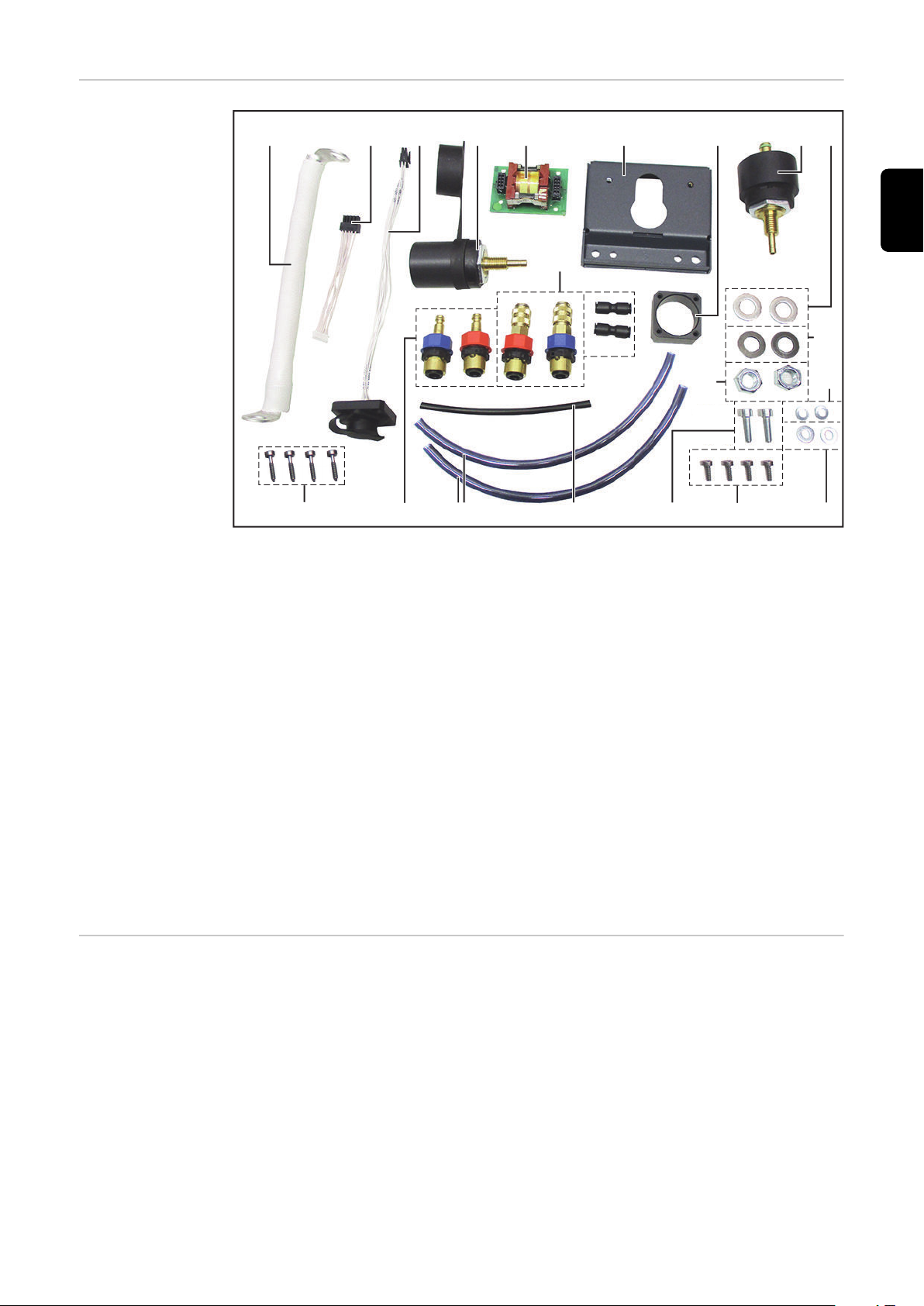
Scope of supply
(1) (2) (3) (4) (5) (6) (7)
(14)
(13)
(12)
(11)
(10)
(8) (9)
(21)
(20)
(18)(19) (17)
(16)
(15)
EN-US
(1) Power cable
(2) Cable 10p
(3) TIG Multi Connector cable
(4) Current socket with cover
(5) PC board
(6) Strain-relief device
(7) TIG Multi Connector mounting
ring
(8) Gas/power connection
(9) 2x washer ISO 7089 M12 A2
(10) 2x disc spring
Do 23 x Di 12.2 x 1.5 mm
(11) 2x hexagonal nut M12
(12) 2x spring lock washer DIN 127
B d6
Tools required
TORX® screwdriver TX 25
-
TORX® screwdriver TX 20
-
19 mm wrench
-
22 mm wrench
-
32 mm wrench
-
5 mm Allen key
-
Knife
-
Drill Ø 8 mm / 0.31 in.
-
(13) 2x washer DIN 134 A M6
(14) 4x screw 4 x 12 mm
(15) 2x Allen screws size 5 mm
(16) Gas hose 0.14 m black
(17) 2x coolant hose 0.5 m
(18) Connection area coolant con-
nections (plug nipple - red,
blue)
(19) 4x screw TX 20, 20 mm
(20) Front coolant connections
(coupling - red, blue)
(21) 2x connection sockets
23
Installing the OPT/i CWF TMC welding torch
3
3
4
Preparation
Switch off the power source and disconnect from the grid
1
Disconnect the CWF 25i wirefeeder from all system components
2
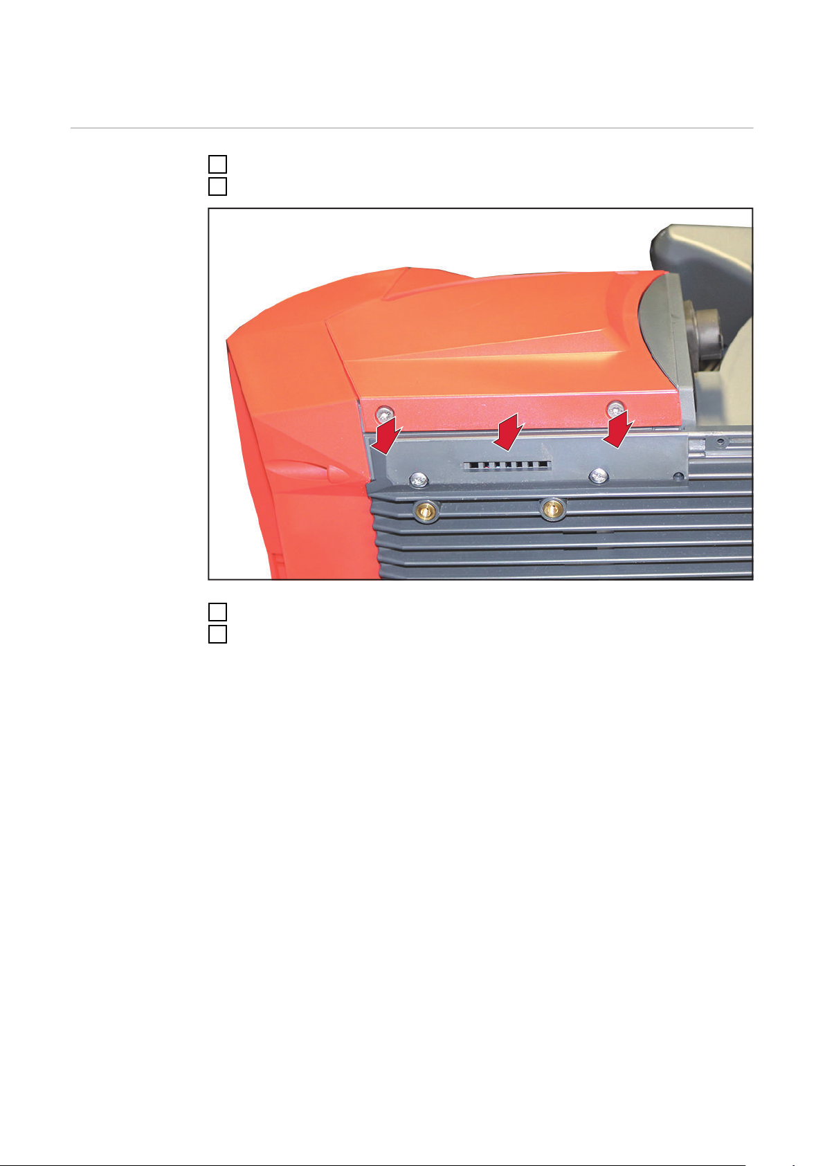
Remove the two TX25 screws
3
Remove the side cover
4
24

6
5
5
5
7
Remove the three dummy covers on the front
8
8
8
5
Cut the film at position "Option"
6
Break the opening
7
EN-US
Remove the three dummy covers in the connection area
8
25

Installing the
1
1
1
1
1
3
3
3
2
2
2
4
5
4
(3)
(4)
(1)
(2)
(5)
(6)
(7)
(8)
OPT/i CWF TMC
welding torch
Remove the five TX25 screws
1
26
Disconnect the three connectors (1), (2), and (3) from the PC board
2
Disconnect the three connectors (4), (5), and (6) from the PC board
3
Disconnect the two data cables (7) and (8) from the PC board
4
Remove the PC board with PC board holder
5

6
8
4x TX20
7
7
7
7
10p
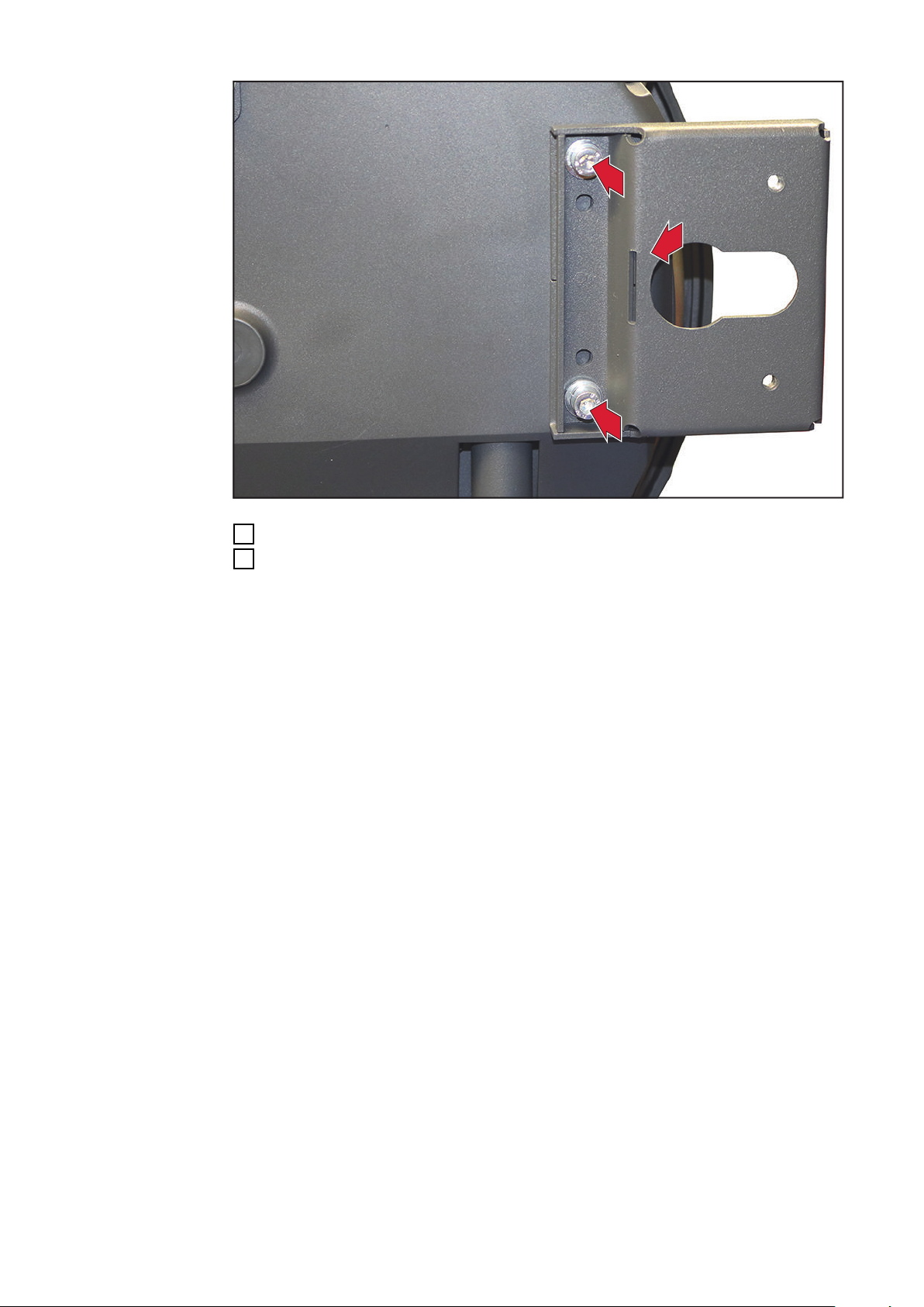
Attach the PC board from the scope of supply to the underside of the pre-
9
9
6
viously removed PC board holder as shown
Secure the PC board using four TX20 screws
7
Tightening torque = 1.2 Nm
Connect cable 10p to the PC board
8
EN-US
Insert the TIG Multi Connector mounting ring into the opening with the holes
9
facing forwards
27

1
2
11
10
10
11
Secure the TIG Multi Connector mounting ring with two TX20 screws from
14
13
15
13
14
15
10
the front
Tightening torque = 3 Nm
Pierce holes
11
Insert the TIG Multi Connector cable from the front
12
28
Secure the TIG Multi Connector socket using two TX20 screws
13
Tightening torque = 3 Nm
Insert the front coolant connections into the openings from inside out as
14
shown
Secure the front coolant connections using two 22 mm hexagonal nuts:
15
red right, blue left – tighten hand-tight

16
17
17
Remove the 32 mm hexagonal nut and insulating washer from the current so-
18
19
18
19
16
cket with cover;
Insert current socket with cover into the opening from the front
Place the insulating washer on the current socket and secure with the 32 mm
17
hexagonal nut on the inside
Tightening torque = 35 Nm
EN-US
Insert the connection area coolant connections into the openings from inside
18
out as shown
Secure the connection area coolant connections using two 22 mm hexagonal
19
nuts:
red top, blue bottom – tighten hand-tight
29

20
2
1
2
1
Remove the 32 mm hexagonal nut and insulating washer from the gas/power
22
2
3
20
connection;
Insert gas/power connection into the opening from the front
Place the insulating washer on the gas/power connection and secure with the
21
32 mm hexagonal nut on the inside
Tightening torque = 35 Nm
30
Attach the power cable to the gas/power connection
22
Secure power cable + washer + disc spring using the 19 mm hexagonal nut
23
Tightening torque = 25 Nm

24
25
Attach the power cable to the front current socket
26
26
24
Secure power cable + washer + disc spring using the 19 mm hexagonal nut
25
Tightening torque = 25 Nm
EN-US
Push the coolant hoses onto the front coolant connections as far as they will
26
go
31

27
27
IMPORTANT! When connecting the coolant hoses to the connection area coo-
28
2
8
2
9
29
lant connections, observe the color markings!
Push the coolant hoses onto the connection area coolant connections as far
27
as they will go
32
Connect the gas hose and connection sockets
28
Connect the gas hose to the power connections
29

Finally...
1
1
2
3
8p
10p
Connecting the
OPT/i CWF TMC
welding torch
EN-US
Remove the two TX25 screws
1
Remove the control panel
2
Connect the TIG Multi Connector cable 8p (from the TMC) to the PC board
3
33

10p
4
IMPORTANT!
When inserting the PC board holder
guide cable 10p from the PC board through the opening
-
make sure that cable 10p is not pinched, kinked, sheared, or damaged in any
-
other way
Feed cable 10p through the opening and insert the PC board holder from the
4
opposite side
34

5
6
Connect cable 10p to X3 on the control panel
7
7
2x TX25
5
IMPORTANT! When inserting the control panel, ensure that the cables are
not pinched, kinked, sheared, or otherwise damaged.
Insert the control panel
6
EN-US
Secure the control panel using two TX25 screws
7
Tightening torque = 2.2 Nm
35

8
8
8
8
8
10
9
9
9
10
10
1
1
1
1
(3)
(4)
(1)
(2)
(5)
(6)
(7)
(8)
Secure the PC board with PC board holder with five TX 25 screws
8
Tightening torque = 3 Nm
36
Connect the three connectors (1), (2), and (3) to the PC board
9
Connect the three connectors (4), (5), and (6) to the PC board
10
Connect the two data cables (7) and (8) to the PC board
11

Final tasks
2x TX25
2
2
1
2x ø 8 mm / 0.31 inch
3
3
Fit the side cover
1
Secure the side cover using two TX25 screws
2
Tightening torque = 1.9 Nm
EN-US
Drill two holes of diameter 8 mm / 0.31 in. in the plastic at the pre-punched
3
positions on the right-hand side of the device
37
4
5
5
Attach the strain-relief device as shown
4
Secure the strain-relief device with two 5 mm Allen screws, washers, and
5
spring lock washers
Tightening torque = 3.5 Nm
38

EN-US
39

 Loading...