

Page 1

Fronius prints on elemental chlorine free paper (ECF) sourced from certified sustainable forests (FSC).
/ Perfect Charging / Perfect Welding / Solar Energy
OPT/i CU 600 Flow-Thermo-Sensor
OPT/i CU 600 flow temperature
sensor
Installationsanleitung
DE
Kühlgerät
Installation instructions
Cooling unit
EN-US
42,0410,2395 002-13092021
Page 2

Page 3

Vorbereitende Informationen und Montage
DE
Sicherheit
WARNUNG!
Gefahr durch Fehlbedienung und fehlerhaft durchgeführte Arbeiten.
Schwerwiegende Personen- und Sachschäden können die Folge sein.
Alle in diesem Dokument beschriebenen Arbeiten und Funktionen dürfen nur von
▶
Fronius-geschultem Servicepersonal ausgeführt werden.
Dieses Dokument lesen und verstehen.
▶
Sämtliche Bedienungsanleitungen der Systemkomponenten, insbesondere Sicher-
▶
heitsvorschriften lesen und verstehen.
WARNUNG!
Gefahr durch elektrischen Strom.
Schwere Verletzungen oder Tod können die Folge sein.
Vor Beginn der Arbeiten alle beteiligten Geräte und Komponenten ausschalten und
▶
von Stromnetz trennen.
Alle beteiligten Geräte und Komponenten gegen Wiedereinschalten sichern.
▶
Nach dem Öffnen des Gerätes mit Hilfe eines geeigneten Messgerätes sicherstel-
▶
len, dass elektrisch geladene Bauteile (beispielsweise Kondensatoren) entladen
sind.
WARNUNG!
Gefahr durch elektrischen Strom wegen unzureichender Schutzleiter-Verbindung.
Schwerwiegende Personen- und Sachschäden können die Folge sein.
Immer die originalen Gehäuse-Schrauben in der ursprünglichen Anzahl verwenden.
▶
VORSICHT!
Gefahr durch heiße Systemkomponenten und heißes Kühlmittel.
Schwere Verbrühungen können die Folge sein.
Alle nachfolgend beschriebenen Arbeiten nur durchführen, wenn das Kühlmittel auf
▶
Zimmertemeratur abgekühlt ist (+25 °C, +77 °F).
Alle nachfolgend beschriebenen Arbeiten nur durchführen, wenn die Systemkompo-
▶
nenten auf Zimmertemeratur abgekühlt sind (+25 °C, +77 °F).
VORSICHT!
Risiko durch Kühlmittel-Austritt.
Schwerwiegende Sachschäden können die Folge sein.
Wenn Kühlmittel an die Außenseite des Kühlgerätes gelangt, dieses sofort entfer-
▶
nen.
Sicherstellen, dass kein Kühlmittel in den Geräteinnenraum gelangt.
▶
3
Page 4

Lieferumfang
4
3
3
3
3
3
1
1
1
2
8x TX25
Erforderliche
Werkzeuge
Vorbereitung
- Schraubendreher TX 25
- Schraubendreher TX 20
- Messer
- Seitenschneider
3 Schrauben TX25 entfernen
1
Rechten Seitenteil entfernen
2
5 Schrauben TX25 entfernen
3
Deckel aufklappen
4
4
Page 5

OPT/i CU 600
(1)
1
(1)
~25 cm
53 cm
3
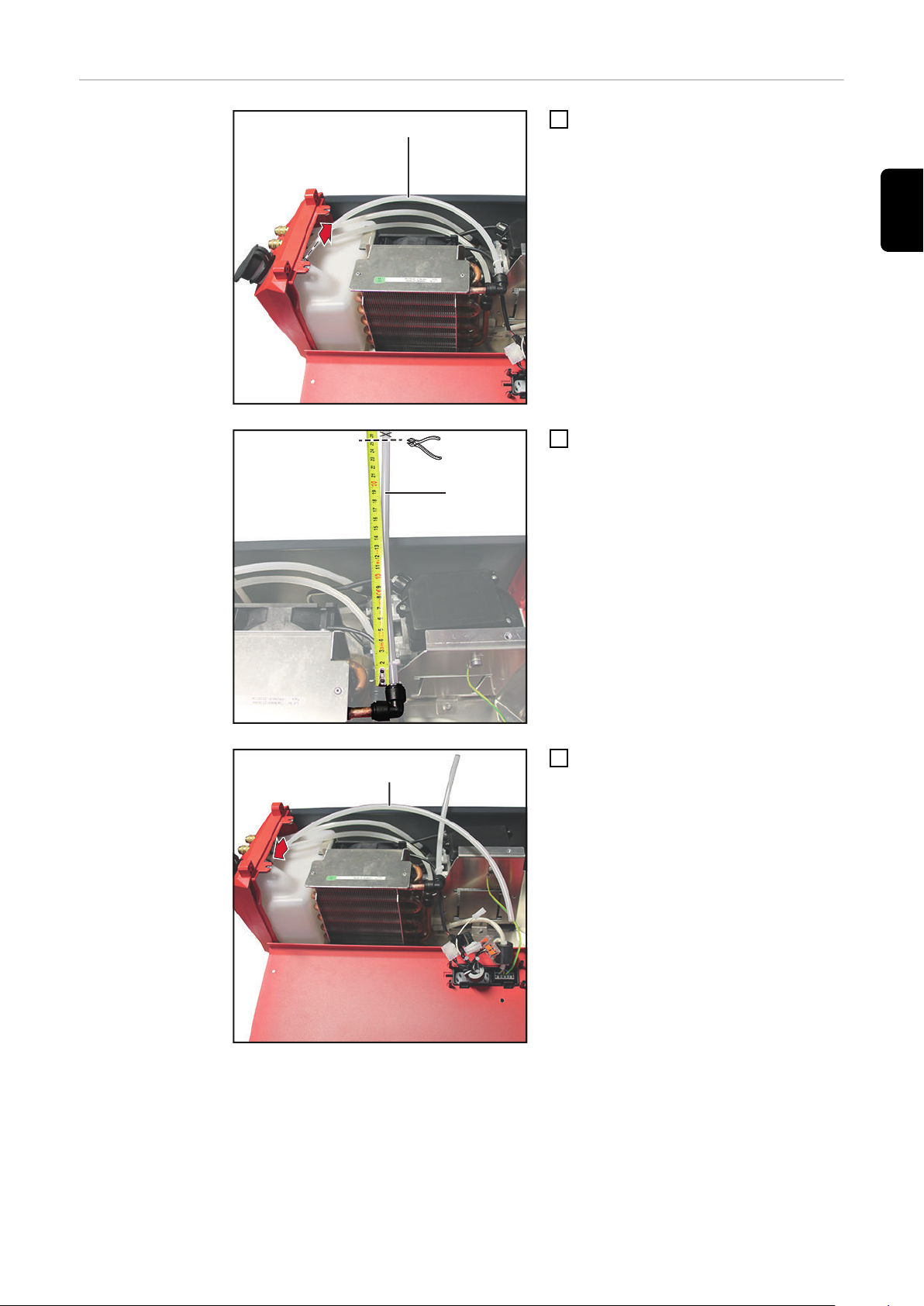
Flow-ThermoSensor einbauen
Obersten Schlauch (1) vom Kühlmit-
1
teltank abstecken
Schlauch (1) auf ca. 25 cm ablängen
2
(gemessen vom Winkelanschluss)
DE
Mitgelieferten Schlauch 53 cm am
3
Kühlmitteltank anstecken
5
Page 6

GND
+
Signal
4
4
4
Kabelbaum gemäß Kabelaufdruck am
IN
OUT
5
25 cm
6
53 cm
8
7
7
8
4
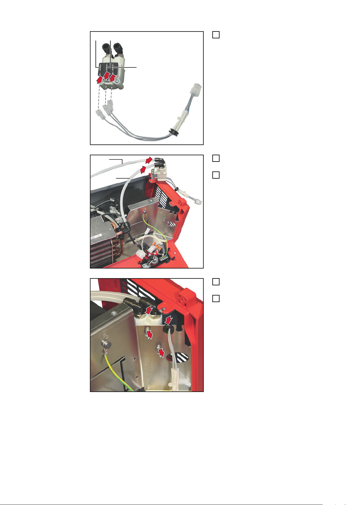
Flow-Sensor anstecken
Schlauch 53 cm am Flow-Sensor am
5
Anschluss OUT anstecken
Schlauch 25 cm am Flow-Sensor am
6
Anschluss IN anstecken
OUT / IN gemäß Pfeil-Markierungen
am Flow-Sensor
Flow-Sensor einsetzen, Gummi-
7
Durchführung in eine freie Öffnung
einsetzen
Flow-Sensor mit 2 Schrauben TX20
8
fixieren
6
Page 7
9
9
Kabel vom Flow-Sensor am Deckel /
a
a
b
1
0
11
1
1
9
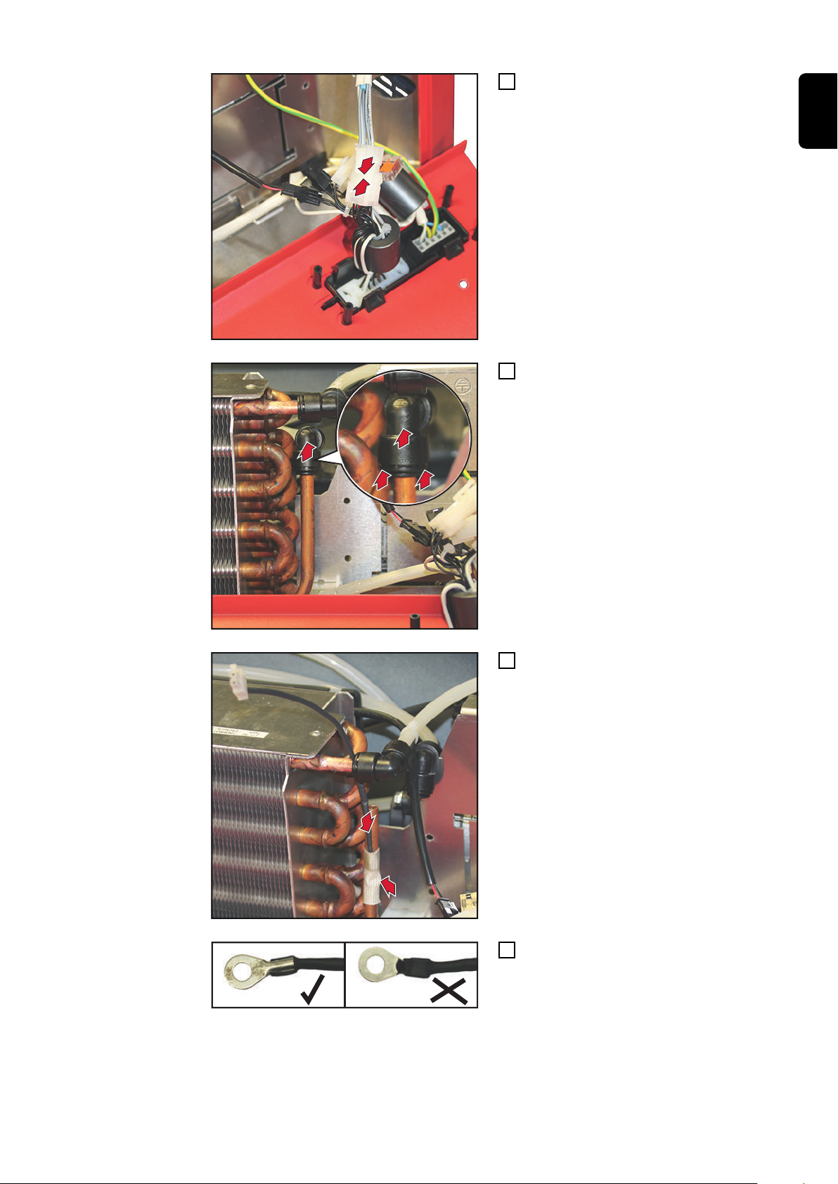
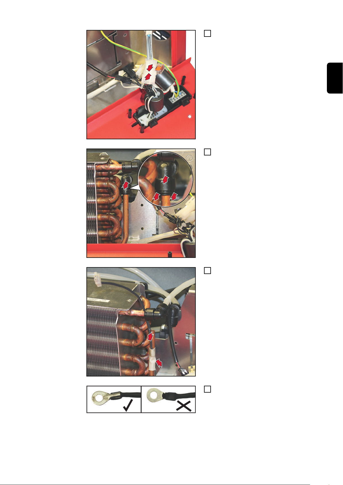
Kabelbaum anstecken
Winkelanschluss lösen:
10
a) Ring nach oben drücken und hal-
ten
b) Anschluss nach oben abziehen
DE
Thermofühler mit der abisolierten
11
Seite zum Kühlrohr - mittels Schutzschlauch am Kühlrohr fixieren
abisolierte Seite
12
7
Page 8

13
14
12
13
Winkelanschluss wieder auf das
13
Kühlrohr aufstecken
Kabel vom Thermofühler am Deckel /
14
Kabelbaum anstecken
Kabel mit Kabelbinder fixieren
15
Kabelbinder ablängen
16
Anbschließende
Tätigkeiten
Deckel mit 5 Schrauben TX25 montieren
1
Anzugsmoment = 3 Nm
Rechten Seitenteil mit 3 Schrauben TX25 montieren
2
Anzugsmoment = 3 Nm
8
Page 9

Preparatory information and installation
Safety
WARNING!
Danger from incorrect operation and work that is not carried out properly.
Serious personal injury and damage to property may result.
All the work and functions described in this document must only be carried out by a
▶
trained Fronius service technician.
Read and understand this document.
▶
Read and understand all the system component Operating Instructions, especially
▶
the safety rules.
WARNING!
Danger from electrical current.
Serious injuries or death may result.
Before starting work, switch off all devices and components involved, and discon-
▶
nect them from the grid.
Secure all devices and components involved so they cannot be switched back on.
▶
After opening the device, use a suitable measuring instrument to check that electri-
▶
cally charged components (such as capacitors) have been discharged.
WARNING!
EN-US
Danger from electrical current due to inadequate ground conductor connection.
Serious personal injury and damage to property may result.
Always use the original housing screws in the quantity initially supplied.
▶
CAUTION!
Danger due to hot system components and hot coolant.
Serious burns may result.
Only perform all work described below when the coolant has cooled down to room
▶
temperature (+25 °C, +77 °F).
Only perform all work described below when the system components have cooled
▶
down to room temperature (+25 °C, +77 °F).
CAUTION!
Risk of coolant escaping.
Serious damage to property may result.
If coolant ends up on the outside of the cooling unit, this should be removed
▶
immediately.
Make sure that no coolant ends up inside the machine.
▶
9
Page 10

Scope of supply
4
3
3
3
3
3
1
1
1
2
8x TX25
Tools required - TX 25 screwdriver
- TX 20 screwdriver
- Knife
- Side cutters
Preparation
Remove 3 TX25 screws
1
Remove right side panel
2
Remove 5 TX25 screws
3
Open lid
4
10
Page 11
Installing OPT/i
(1)
1
(1)
~25 cm
53 cm
3
CU 600 flow temperature sensor
Disconnect the top hose (1) from the
1
coolant tank
Cut off the hose (1) to about 25 cm
2
(measured from the angle connection)
EN-US
Connect the 53 cm hose supplied to
3
the coolant tank
11
Page 12
GND
+
Signal
4
4
4
Connect the cable harness as per the
IN
OUT
5
25 cm
6
53 cm
8
7
7
8
4
cable label on the flow sensor
Connect the 53 cm hose to the flow
5
sensor at the OUT connection
Connect the 25 cm hose to the flow
6
sensor at the IN connection
OUT / IN as per the arrows on the flow
sensor
Insert the flow sensor, insert the rub-
7
ber bushing into a free opening
Secure the flow sensor with 2 TX20
8
screws
12
Page 13
9
9
Connect the cable from the flow sen-
a
a
b
1
0
11
1
1
9
sor to the lid/cable harness
Loosen the angle connection:
10
a) Push the ring up and hold it
b) Pull the connection off upwards
EN-US
Use the protective hose to secure the
11
temperature sensor to the cooling tube
with the stripped end to the cooling
tube
Stripped end
12
13
Page 14

13
14
12
13
Place the angle connection back onto
13
the cooling tube
Connect the cable from the tempera-
14
ture sensor to the lid/cable harness
Fix the cable in place using a cable tie
15
Trim the cable tie
16
Final tasks
Install the lid using 5 TX25 screws
1
Tightening torque = 3 Nm
Mount the right panel using 3 TX25 screws
2
Tightening torque = 3 Nm
14
Page 15

EN-US
15
Page 16

FRONIUS INTERNATIONAL GMBH
Froniusstraße 1
A-4643 Pettenbach
AUSTRIA
contact@fronius.com
www.fronius.com
Under www.fronius.com/contact you will find the addresses
of all Fronius Sales & Service Partners and locations
 Loading...