

Page 1
Operating
instructions
OPT/HP ext. Torch Deflate
DE
EN-US
Bedienungsanleitung
Operating instructions
42,0410,2731 001-10052022
Page 2

Page 3

Inhaltsverzeichnis
Allgemeines 4
Gerätekonzept 4
Vor Installation und Inbetriebnahme 4
Für den Betrieb erforderlich 5
Anschlüsse 6
Anwendungsbeispiel 7
Funktionsprinzip 8
Schaltschema 8
Programmablauf 8
Schaltschema elektrisch 9
DE
3
Page 4
Allgemeines
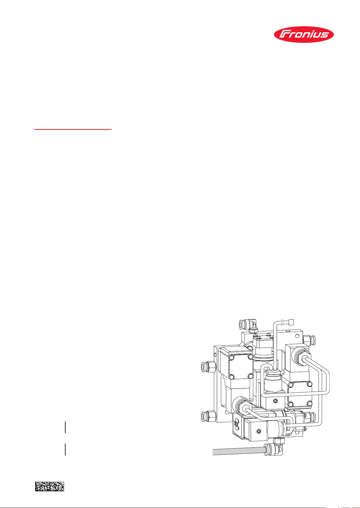
Gerätekonzept Mit der Option OPT/HP ext. Torch de-
flate kann das Kühlmittel aus dem
Schweißbrenner-Schlauchpaket
zurück in den Kühlmitteltank
befördert werden, beispielsweise beim
Wechsel des Brennerkörpers.
Die Stromquelle muss dabei nicht ausgeschaltet werden.
Beim Entleeren des SchweißbrennerSchlauchpaketes wird der Kühlkreis im
Verbindungs-Schlauchpaket über einen Bypass geöffnet.
Das Entleeren des SchweißbrennerSchlauchpaketes erfolgt über einen
Rücklaufschlauch direkt zum Kühlmittel-Tank, unabhängig von der Länge
des Verbindungs-Schlauchpaketes.
Vor Installation
und Inbetriebnahme
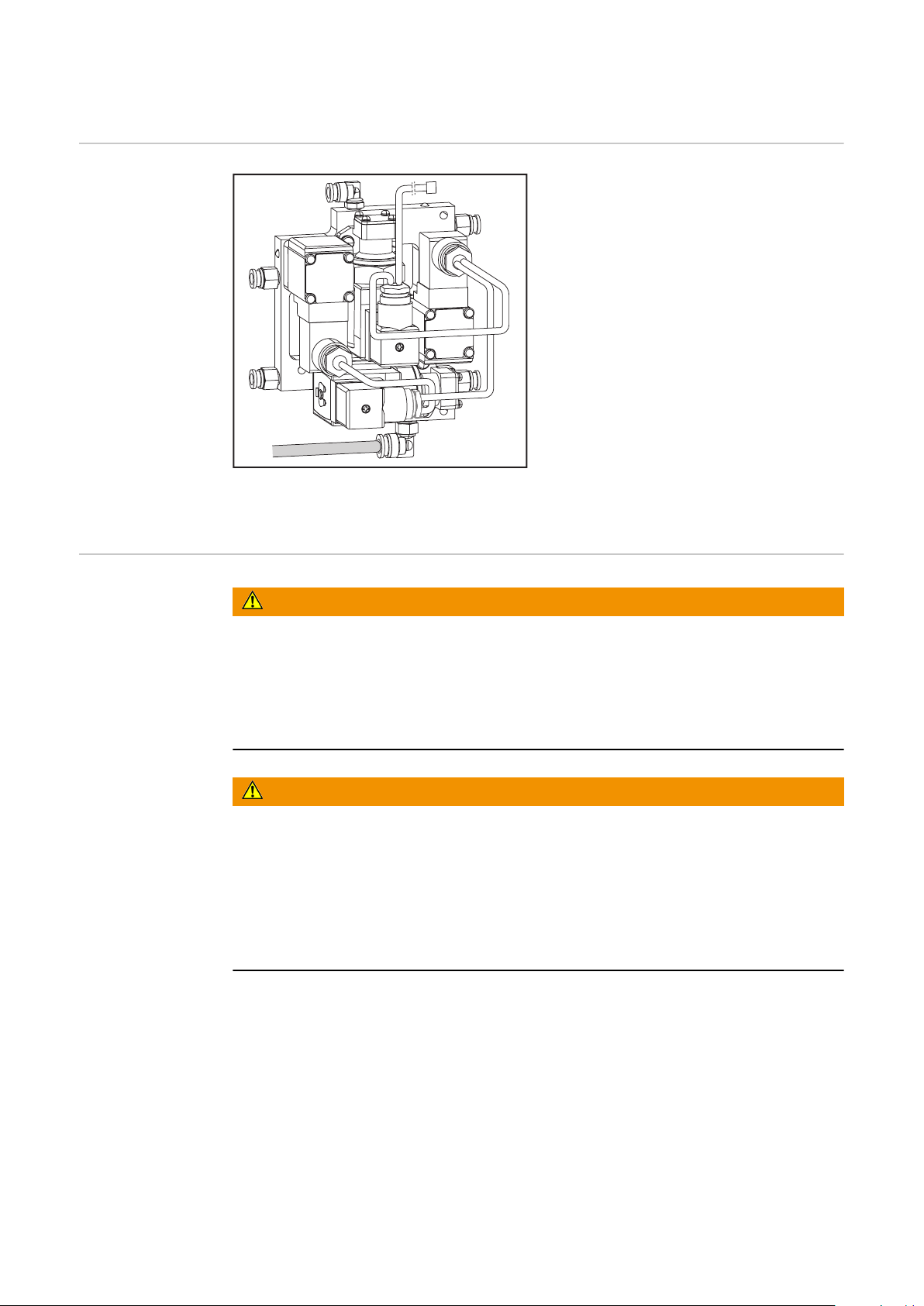
WARNUNG!
Ein elektrischer Schlag kann tödlich sein.
Ist das Gerät während der Installation am Netz angesteckt, besteht die Gefahr
schwerwiegender Personen und Sachschäden. Sämtliche Arbeiten am Gerät nur
durchführen, wenn
der Netzschalter in Stellung - O - geschaltet ist,
▶
das Gerät vom Netz getrennt ist.
▶
WARNUNG!
Gefahr durch heiße Systemkomponenten und / oder Betriebsmittel.
Schwere Verbrennungen und Verbrühungen können die Folge sein.
Vor Beginn der Arbeiten alle heißen Systemkomponenten und / oder Be-
▶
triebsmittel auf +25 °C / +77 °F abkühlen lassen (beispielsweise Kühlmittel,
wassergekühlte Systemkomponenten, Antriebsmotor des Drahtvorschubes, ...).
Geeignete Schutzausrüstung tragen (beispielsweise hitzebeständige Schutz-
▶
handschuhe, Schutzbrille, ...), wenn ein Abkühlen nicht möglich ist.
4
Page 5

Für den Betrieb
erforderlich
OPT/HP ext. Torch deflate
inkl.
Ventilplatte
-
Steckverbindungen 6 mm
-
Stecknippel 10 mm
-
Steuerleitung M12, 3-polig
10 m
-
oder
20 m
-
oder
40 m
-
Druckluft-Regler
Druckluft-Regler 1/4“
-
oder
Filter-Regler AW30 F03H G3/8“
-
(Option)
4,101,360
43,0004,6401
43,0004,6402
43,0004,6403
68,0600,1381
42,0510,0121
DE
OPT/TD Set MIG/MAG
inkl.
Steckverbindungen 6 mm
-
Stecknippel 10 mm
-
Schlauch 8/6 mm PE
-
Schlauch 8/6 mm PUR
-
Schlauch 16/10 mm Gewebe
-
1-Ohr-Klemme 17,8 mm
-
1-Ohr-Klemme 9 mm
-
Tankverschluss Torch Deflate
-
CU 2000
Haltewinkel WF 30i TWIN (Option) 45,1200,0433
Druckluft-Versorgung min. 3 bar
4,101376,CK
5
Page 6
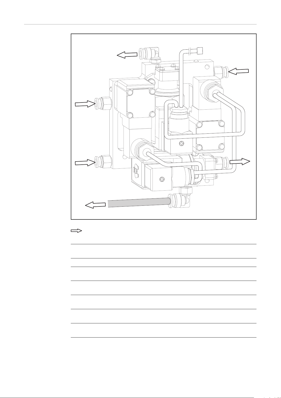
Anschlüsse
M12
AIR IN
TO OUT
TO IN
CU TANK
CU IN
CU OUT
Fließ-Richtung
TO OUT Kühlflüssigkeit Vorlauf
zum Schweißbrenner-Schlauchpaket
M12 Anschluss Steuerleitung M12, 3-polig
CU IN Kühlflüssigkeit Vorlauf
via Verbindungs-Schlauchpaket vom Kühlgerät
AIR IN Anschluss Druckluft 1 - 3 bar
vom Druckregler
TO IN Kühlflüssigkeit Rücklauf
aus dem Schweißbrenner-Schlauchpaket
CU OUT Kühlflüssigkeit Rücklauf
via Verbindungs-Schlauchpaket zum Kühlgerät
CU TANK direkte Leitung zum Kühlmittel-Tank des Kühlgerätes zum Ent-
leeren des Schweißbrenner-Schlauchpaketes
CU = Kühlgerät, TO = Schweißbrenner, AIR = Druckluft
6
Page 7
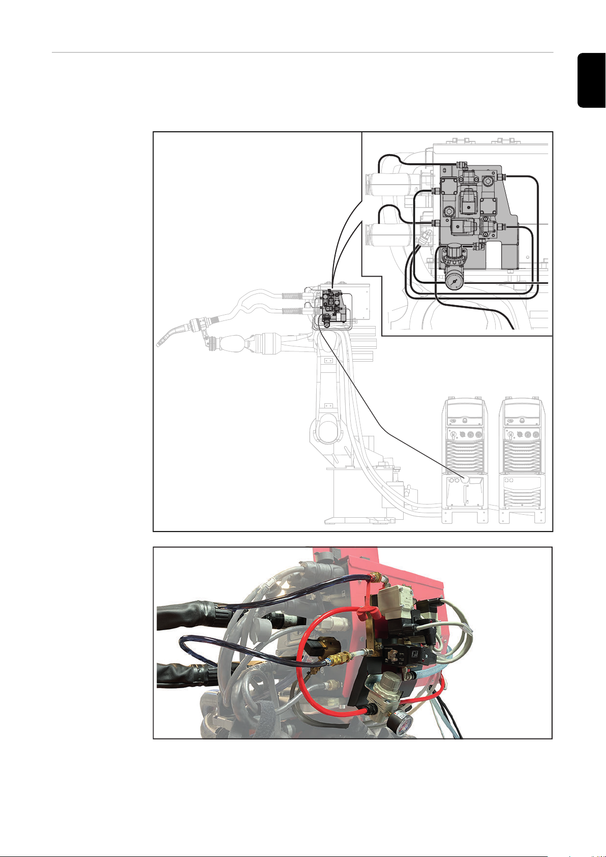
Anwendungsbei-
TO OUT
AIR IN
CU TANK
TO IN
CU IN
CU OUT
CU TANK
spiel
TWIN-Schweißanlage mit OPT/HP ext. Torch deflate, montiert am TWIN-Drahtvorschub WF 30i TWIN
CU = Kühlgerät, TO = Schweißbrenner, AIR = Druckluft
DE
7
Page 8

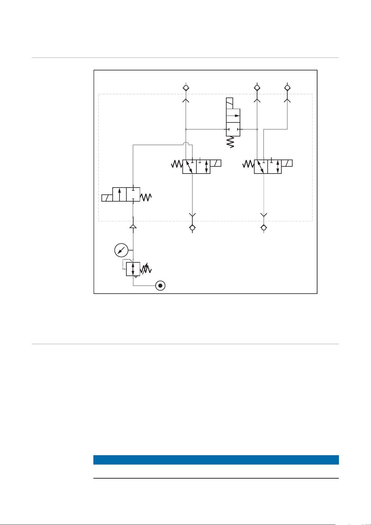
Funktionsprinzip
1
2
1
2
3
CU IN
1
2
3
1
2
CU OUT CU TANK
AIR IN TO INTO OUT
(A)
(B)
(C)
(D)
11
Schaltschema
Programmablauf
CU = Kühlgerät, TO = Schweißbrenner, AIR = Druckluft
Schweißende
1.
Signal Ventile (A) + (B) + (C) ein
2.
Verweilzeit: 1 Sekunde
3.
Signal Ventil (D) ein
4.
Verweilzeit: bis zur vollständigen Entleerung des Schweißbrenner-Schlauch-
5.
paketes (ca. 20 Sekunden)
Signal Ventil (D) aus (Entlüftung Druckluft)
6.
Verweilzeit: 5 Sekunden
7.
Schweißbrenner-Wechsel durchführen
8.
Verweilzeit nach dem Ankoppeln des Brennerkörpers: 1 Sekunde
9.
Signal Ventile (A) + (B) + (C) aus
10.
Bereit zum Schweißen
11.
HINWEIS!
Bei einem aktiven Ventil leuchtet die LED des Ventils.
8
Page 9
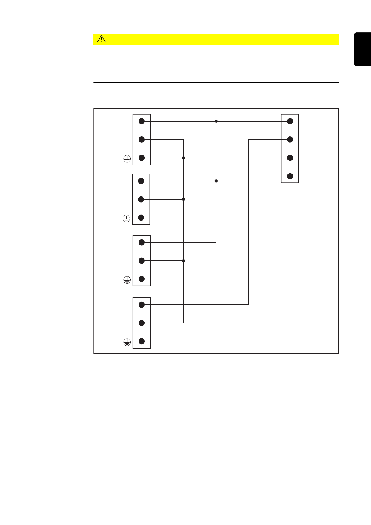
VORSICHT!
(A)
(B)
(C)
(D)
(E)
1
2
1
2
1
2
1
2
1
2
3
4
1 = +24 V DC → A/B/C
2 = +24 V DC → D
3 = GRD
Schaltschema
elektrisch
Überhitzungsgefahr durch falsch geschaltete Ventile!
Sachschäden bis zur Zerstörung des Schweißbrenner-Schlauchpaketes können
die Folge sein.
Nicht schweißen, wenn die Ventile (A), (B) und (C) eingeschaltet sind.
▶
DE
9
Page 10

10
Page 11

Table of contents
General 12
Device concept 12
Before installation and commissioning 12
Required for operation 13
Connections 14
Application example 15
Functional principle 16
Circuit diagram 16
Program sequence 16
Electrical circuit diagram 17
EN-US
11
Page 12

General
Device concept With the option OPT/HP ext. Torch de-
flate, the coolant can be transported
from the torch hosepack back to the
coolant tank, for example when changing the torch body.
The power source does not have to be
switched off during this process.
When the torch hosepack is drained,
the cooling circuit in the interconnecting hosepack is opened via a bypass.
The torch hosepack is drained via a return hose directly to the coolant tank,
regardless of the length of the interconnecting hosepack.
Before installation and commissioning
WARNING!
An electric shock can be fatal.
If the unit is connected to the grid during installation, there is a danger of serious
injury and damage to property. All work on the device may only be carried when:
The power switch is set to - O -
▶
The device has been disconnected from the grid
▶
WARNING!
Danger due to hot system components and/or equipment.
This can result in serious burns or scalding.
Before starting work, allow all hot system components and/or equipment to
▶
cool to +25°C/+77°F (e.g., coolant, water-cooled system components, wirefeeder drive motor, etc.).
Wear suitable protective equipment (e.g., heat-resistant gloves, safety gog-
▶
gles, etc.) if cooling down is not possible.
12
Page 13

Required for
operation
OPT/HP ext. Torch deflate
Incl.
Valve plate
-
Plug connections 6 mm
-
Plug nipple 10 mm
-
Control line M12, 3-pin
10 m
-
or
20 m
-
or
40 m
-
Compressed air regulator
Compressed air regulator 1/4"
-
or
Filter regulator AW30 F03H
-
G3/8" (option)
4,101,360
EN-US
43,0004,6401
43,0004,6402
43,0004,6403
68,0600,1381
42,0510,0121
OPT/TD Set MIG/MAG
Incl.
Plug connections 6 mm
-
Plug nipple 10 mm
-
Hose 8/6 mm PE
-
Hose 8/6 mm PUR
-
Hose 16/10 mm fabric
-
1-ear clamp 17.8 mm
-
1-ear clamp 9 mm
-
Torch Deflate CU 2000 tank cap
-
WF 30i TWIN mounting bracket (option)
Compressed air supply min. 3 bar
4,101376,CK
45,1200,0433
13
Page 14

Connections
M12
AIR IN
TO OUT
TO IN
CU TANK
CU IN
CU OUT
Flow direction
TO OUT Coolant supply
to torch hosepack
M12 Control line M12, 3-pin connection
CU IN Coolant supply
via interconnecting hosepack from cooling unit
AIR IN Compressed air connection 1 - 3 bar
from pressure regulator
TO IN Coolant return
from the torch hosepack
CU OUT Coolant return
via interconnecting hosepack to the cooling unit
CU TANK Direct line to the coolant tank of the cooling unit for draining
the torch hosepack
CU = cooling unit, TO = welding torch, AIR = compressed air
14
Page 15

Application ex-
TO OUT
AIR IN
CU TANK
TO IN
CU IN
CU OUT
CU TANK
ample
TWIN welding system with OPT/HP ext. Torch deflate, mounted on TWIN wire-
feeder WF 30i TWIN
CU = cooling unit, TO = welding torch, AIR = compressed air
EN-US
15
Page 16
Functional principle
1
2
1
2
3
CU IN
1
2
3
1
2
CU OUT CU TANK
AIR IN TO INTO OUT
(A)
(B)
(C)
(D)
11
Circuit diagram
Program sequence
CU = cooling unit, TO = welding torch, AIR = compressed air
End of welding
1.
Signal valves (A) + (B) + (C) on
2.
Dwell time: 1 second
3.
Signal valve (D) on
4.
Dwell time: until the torch hosepack is completely empty (approx. 20 se-
5.
conds)
Signal valve (D) off (venting compressed air)
6.
Dwell time: 5 seconds
7.
Carry out welding torch change
8.
Dwell time after coupling the torch body: 1 second
9.
Signal valves (A) + (B) + (C) off
10.
Ready for welding
11.
NOTE!
When the valve is active, the LED of the valve lights up.
16
Page 17
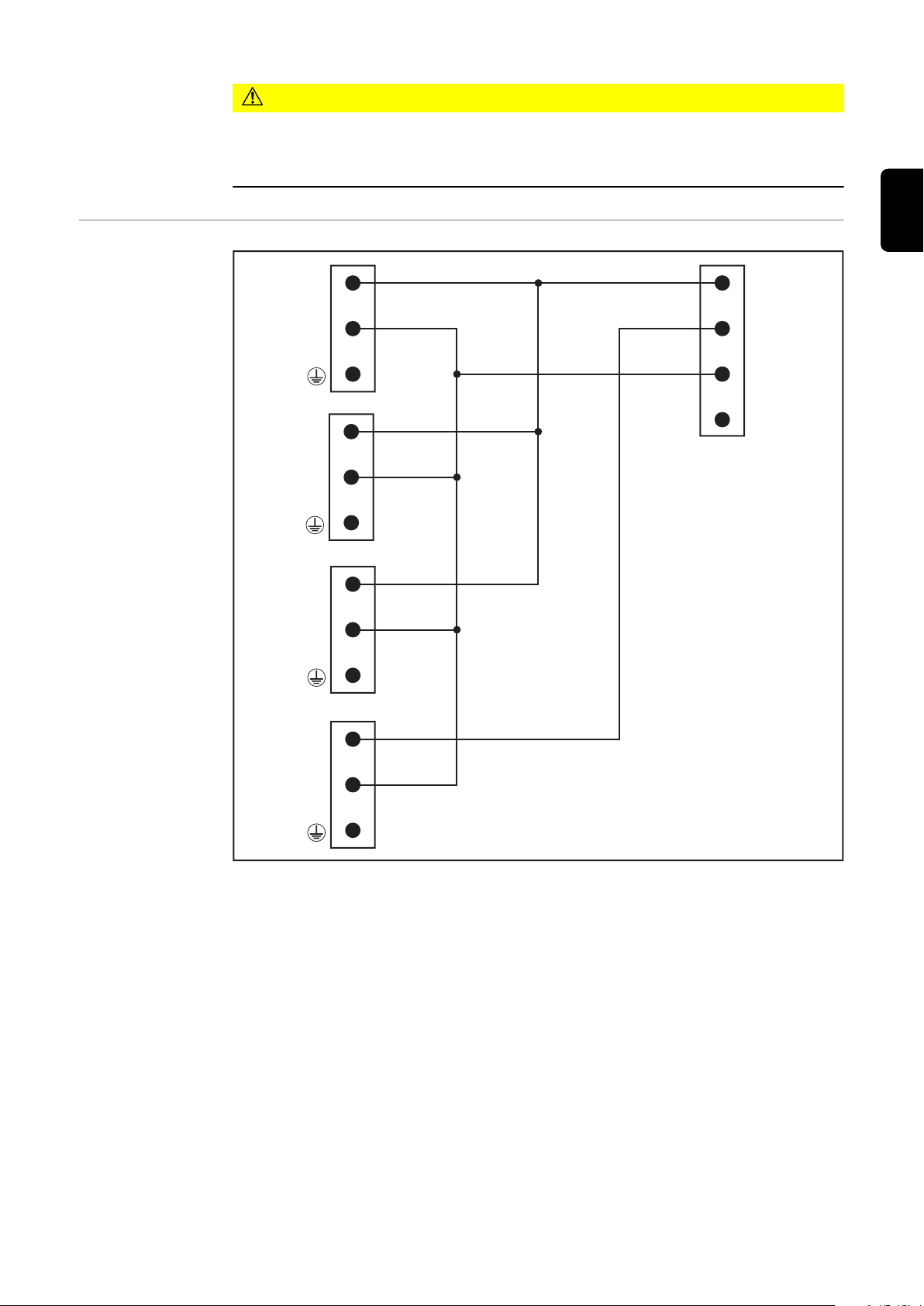
Electrical circuit
(A)
(B)
(C)
(D)
(E)
1
2
1
2
1
2
1
2
1
2
3
4
1 = +24 V DC → A/B/C
2 = +24 V DC → D
3 = GRD
diagram
CAUTION!
Risk of overheating due to incorrectly switched valves!
This may result in material damage or even destruction of the torch hosepack.
Do not weld when valves (A), (B), and (C) are on.
▶
EN-US
17
Page 18

18
Page 19

EN-US
19
Page 20

 Loading...