

Page 1

Fronius prints on elemental chlorine free paper (ECF) sourced from certified sustainable forests (FSC).
/ Perfect Charging / Perfect Welding / Solar Energy
OPT Easy Documentation TSt
Installationsanleitung
DE
Systemerweiterung
Installation instructions
System extension
EN-US
42,0410,2626 001-16102020
Page 2

Page 3

Inhaltsverzeichnis
Allgemeines 4
Sicherheit 4
Lieferumfang 4
ErfoderlicheWerkzeuge 5
OPT Easy Documentation in TSt 3500 / 5000 Syn und in TSt 4000 / 5000 Pulse einbauen 6
Vorbereitung 6
OPT Easy Documentation in TSt 3500 / 5000 Syn und in TSt 4000 / 5000 Pulse einbauen 6
Abschließende Tätigkeiten 9
OPT Easy Documentation in TSt 3000 c Pulse und in TSt 3500 c einbauen 10
Vorbereitung 10
OPT Easy Documentation in TSt 3000 c Pulse und in TSt 3500 c einbauen 10
Abschließende Tätigkeiten 12
DE
3
Page 4

Allgemeines
(1)
(2)
(3)
(4)
(5)
(6)
(7)
(8)
(13)
(12)
(11)
(10)
(1)
(2)
(3) (4)(5)(6)(7)
(12)(14)
Sicherheit
Lieferumfang
WARNUNG!
Ein elektrischer Schlag kann tödlich sein.
Vor Öffnen des Gerätes
Netzschalter in Stellung - O - schalten
▶
Gerät vom Netz trennen
▶
ein verständliches Warnschild gegen Wiedereinschalten anbringen
▶
mit Hilfe eines geeigneten Messgerätes sicherstellen, dass elektrisch geladene Bau-
▶
teile (z.B. Kondensatoren) entladen sind
WARNUNG!
Fehlerhaft durchgeführte Arbeiten können schwerwiegende Personen- und
Sachschäden verursachen.
Nachfolgend beschriebene Tätigkeiten dürfen nur von geschultem Fachpersonal
▶
durchgeführt werden!
Beachten Sie das Kapitel „Sicherheitsvorschriften“ in der Bedienungsanleitung der
▶
Stromquelle und der Systemkomponenten.
4
Lieferumfang OPT Easy Documentation TSt
(1) Kabelbaum
(2) Print DOCMAG
(3) USB-Kabel
(4) USB-Stick
(5) USB-Abdeckung
(6) USB-Verstrebung
(7) Kunststoff-Distanz M4 x 12 mm
(8) Messing-Distanz M5 x 30 mm
(9) Messing-Distanz M5 x 12 mm
(10) Kunststoff-Distanz M4 x 27mm
(11) Spreizanker
(12) Kabelbinder
Lieferumfang OPT Easy Documentation TSt c
Page 5

(13) Print-Halterung
(14) Print-Distanz M4 x 24 mm
Ohne Abbildung:
diese Installationsanleitung
Kurzanleitung Easy Documentation
DE
ErfoderlicheWerkzeuge
- Torx-Schraubendreher TX25
- Steckschlüssel M4, M5
- Schlitz-Schraubendreher
- Seitenschneider
5
Page 6

OPT Easy Documentation in TSt 3500 / 5000 Syn
2x TX25
3
2
1
5x TX25
7
2
1
3
4
6
5
1
1
1
5
NT2501
*
5
5
5
*
*
**
und in TSt 4000 / 5000 Pulse einbauen
Vorbereitung
Linken und rechten Seitenteil entfernen (je 5 Schrauben TX25)
1
2
3
Rechteck am Aufkleber „Easy Documentation“ ausschneiden
5 Schrauben TX25 entfernen
Rückseite herausklappen
OPT Easy Documentation in TSt
3500 / 5000 Syn
und in TSt 4000 /
5000 Pulse einbauen
1
Blechteil ausbrechen
2
Am Print NT2501 4 Distanzen aufschrauben:
* Kunststoff-Distanz M4 x 30 mm - 0,2 Nm
** Messing-Distanz M5 x 30 mm - 1,5 Nm
6
Page 7

2
1
3
1
2
3
5
4
7
6
*
*
*
**
1
X10
X10
1
3
2
4
4
DE
Kabelbaum und USB-Kabel am Print DOCMAG
anstecken
5
Vorhandenes Kabel vom Print LSTMAGxx / X10
abstecken
USB-Kabel und Kabelbaum durch die Durchführung
auf die andere Geräteseite verlegen
Print DOCMAG mit Halterung gemäß Abbildung einsetzen
Print-Halterung mit 4 Distanzen fixieren:
* Kunststoff-Distanz M4 x 12 mm - 0,2 Nm
** Messing-Distanz M5 x 12 mm - 1,5 Nm
6
6-poligen Stecker vom Kabelbaum am Print LSTMAGxx / X10 anstecken
Kabelbinder lösen
7
Page 8

2
1
7
1
1
2
1
1
1
1
2
8
Kabel vom Bedienpanel abstecken
Kabel entfernen
9
USB-Abdeckung in die Öffnung an der Rückseite einsetzen
USB-Verstrebung an der Innenseite auf die USBAbdeckung aufdrücken
6-poligen Clik-Mate-Stecker vom Kabelbaum am
Bedienpanel anstecken und mit Kabelbindern und
Spreizankern fixieren
10
USB-Kabel zur Rückseite verlegen
USB-Kabel in die USB-Abdeckung einsetzen
Korrekt montierter USB-Anschluss:
8
Page 9

Abschließende
Tätigkeiten
Rückseite mit 5 Schrauben TX25 montieren
1
Anzugsmoment = 3 Nm
Bedienpanel mit 2 Schrauben TX25 montieren
2
Anzugsmoment = 3,8 Nm
Linken und rechten Seitenteil mit je 5 Schrauben TX25 montieren
3
Anzugsmoment = 3 Nm
DE
9
Page 10
OPT Easy Documentation in TSt 3000 c Pulse und
1
1
1
1
1
2
in TSt 3500 c einbauen
Vorbereitung
OPT Easy Documentation in TSt
3000 c Pulse und
in TSt 3500 c einbauen
Rechten Seitenteil entfernen (5 Schrauben TX25)
1
5 Schrauben TX25 an der Rückseite entfernen und Rückseite herausklappen
2
3
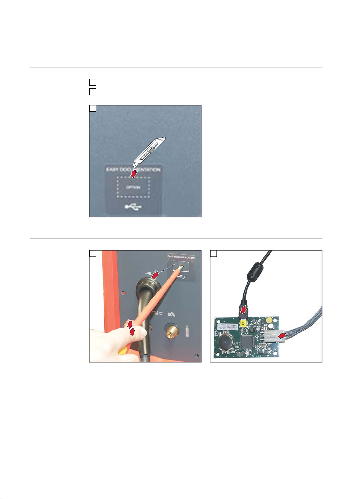
Rechteck am Aufkleber „Easy Documentation“ ausschneiden
1
2
10
Blechteil ausbrechen
Kabelbaum und USB-Kabel am Print DOCMAG
anstecken
Page 11

4
3
1
2
3
1
5
4
2
3
X10
1
1
2
1
4
DE
Rückseitig 4 Kunststoff-Distanzen M4 x 12 mm auf
die vorhandenen Gewindebolzen aufschrauben (0,2
Nm)
5
Kabelbaum am Print LSTMAGxx am freien Stecker
X10 anstecken
7
Print DOCMAG gemäß Abbildung einsetzen
Print DOCMAG mit 4 Print-Distanzen M4 x 24 mm
fixieren (0,2 Nm)
6
USB-Abdeckung in die Öffnung an der Rückseite einsetzen
USB-Verstrebung an der Innenseite auf die USBAbdeckung aufdrücken
USB-Kabel in die USB-Abdeckung einsetzen
Korrekt montierter USB-Anschluss
11
Page 12

Abschließende
Tätigkeiten
Rückseite einsetzen und mit 5 Schrauben TX25 fixieren
1
Anzugsmoment = 3 Nm
Rechten Seitenteil mit 5 Schrauben TX25 montieren
2
Anzugsmoment = 3 Nm
12
Page 13

Table of contents
General 14
Safety 14
Scope of supply 14
Required tools 15
Installing the OPT Easy Documentation in the TransSteel 3500 / 5000 Syn and TransSteel 4000 /
5000 Pulse
Preparation 16
Installing the OPT Easy Documentation in the TransSteel 3500 / 5000 Syn and TransSteel 4000 /
5000 Pulse
Final tasks 19
Installing the OPT Easy Documentation in the TransSteel 3000 c Pulse and TransSteel 3500 c 20
Preparation 20
Installing the OPT Easy Documentation in the TransSteel 3000 c Pulse and TransSteel 3500 c 20
Final tasks 22
16
16
EN-US
13
Page 14

General
(1)
(2)
(3)
(4)
(5)
(6)
(7)
(8)
(13)
(12)
(11)
(10)
(1)
(2)
(3) (4)(5)(6)(7)
(12)(14)
Safety
Scope of supply
WARNING!
An electric shock can be fatal.
Before opening the device
Set the power switch to - O -
▶
Unplug the device from grid power
▶
Attach a clear warning sign advising others not to switch the power source back on
▶
Use a suitable measuring instrument to ensure that electrically charged components
▶
(e.g., capacitors) are discharged
WARNING!
Work performed incorrectly can cause serious injury and damage to property.
Only trained and qualified personnel may carry out the activities described in the fol-
▶
lowing.
Please note the information in the "Safety Rules" chapter in the Operating Instruc-
▶
tions for the power source and the system components.
14
Scope of supply OPT Easy Documentation TransSteel
(1) Cable harness
(2) DOCMAG PC board
(3) USB cable
(4) USB thumb drive
(5) USB cover
(6) USB support
(7) Plastic spacer M4 x 12 mm
(8) Brass spacer M5 x 30 mm
(9) Brass spacer M5 x 12 mm
(10) Plastic spacer M4 x 27 mm
(11) Expansion anchor
(12) Cable ties
Scope of supply OPT Easy Documentation TransSteel c
Page 15

(13) PC board holder
(14) PC board spacer M4 x 24 mm
Not shown:
These Installation Instructions
Quick Guide Easy Documentation
Required tools - Torx screwdriver TX25
- Socket wrench M4, M5
- Slotted screwdriver
- Diagonal cutting pliers
EN-US
15
Page 16

Installing the OPT Easy Documentation in the
2x TX25
3
2
1
5x TX25
7
2
1
3
4
6
5
1
1
1
5
NT2501
*
5
5
5
*
*
**
TransSteel 3500 / 5000 Syn and TransSteel 4000 /
5000 Pulse
Preparation
Remove the left and right side panel (5 TX25 screws each)
1
2
3
Cut out the rectangle on the "Easy Documentation"
sticker
Remove 5 TX25 screws
Fold out the rear panel
Installing the OPT
Easy Documentation in the TransSteel 3500 / 5000
Syn and TransSteel 4000 / 5000
Pulse
16
1
Knock out the sheet metal part
2
Screw 4 spacers onto the NT2501 PC board:
* Plastic spacer M4 x 30 mm - 0.2 Nm
** Brass spacer M5 x 30 mm - 1.5 Nm
Page 17

2
1
3
1
2
3
5
4
7
6
*
*
*
**
1
X10
X10
1
3
2
4
4
EN-US
Connect the cable harness and USB cable to the
DOCMAG PC board
5
Disconnect the existing cable from the LSTMAGxx
PC board / X10
Route the USB cable and cable harness through the
bushing to the other side of the device
Insert the DOCMAG PC board with holder as shown
Secure the PC board holder with 4 spacers:
* Plastic spacer M4 x 12 mm - 0.2 Nm
** Brass spacer M5 x 12 mm - 1.5 Nm
6
Connect the 6-pin plug from the cable harness to the
LSTMAGxx PC board / X10
Undo cable ties
17
Page 18

2
1
7
1
1
2
1
1
1
1
2
8
Disconnect the cable from the control panel
Remove the cable
9
Insert the USB cover into the opening on the rear
panel
Press the USB support on the inside onto the USB
cover
Connect the 6-pin Clik-Mate plug from the cable
harness to the control panel and secure it with cable
ties and expansion anchors
10
Route the USB cable to the rear panel
Insert the USB cable into the USB cover
Correctly mounted USB port:
18
Page 19

Final tasks
Install the rear panel using 5 TX25 screws
1
Tightening torque = 3 Nm
Install the control panel using 2 TX25 screws
2
Tightening torque = 3.8 Nm
Mount the left and right side panel using 5 TX25 screws each
3
Tightening torque = 3 Nm
EN-US
19
Page 20

Installing the OPT Easy Documentation in the
1
1
1
1
1
2
TransSteel 3000 c Pulse and TransSteel 3500 c
Preparation
Installing the OPT
Easy Documentation in the TransSteel 3000 c
Pulse and TransSteel 3500 c
Remove the right side panel (5 TX25 screws)
1
Remove the 5 TX25 screws on the rear panel and fold out the rear panel
2
3
Cut out the rectangle on the "Easy Documentation" sticker
1
2
20
Knock out the sheet metal part
Connect the cable harness and USB cable to the
DOCMAG PC board
Page 21

4
3
1
2
3
1
5
4
2
3
X10
1
1
2
1
4
EN-US
Screw 4 M4 x 12 mm plastic spacers onto the existing threaded bolts at the rear (0.2 Nm)
5
Connect the cable harness on the LSTMAGxx PC
board to the free X10 connector
7
Insert the DOCMAG PC board as shown
Secure the DOCMAG PC board with 4 M4 x 24 mm
PC board spacers (0.2 Nm)
6
Insert the USB cover into the opening on the rear
panel
Press the USB support on the inside onto the USB
cover
Insert the USB cable into the USB cover
Correctly mounted USB port
21
Page 22

Final tasks
Insert the rear panel and secure with 5 TX25 screws
1
Tightening torque = 3 Nm
Mount the right side panel using 5 TX25 screws
2
Tightening torque = 3 Nm
22
Page 23

EN-US
23
Page 24

FRONIUS INTERNATIONAL GMBH
Froniusstraße 1
A-4643 Pettenbach
AUSTRIA
contact@fronius.com
www.fronius.com
Under www.fronius.com/contact you will find the addresses
of all Fronius Sales & Service Partners and locations.
 Loading...