

Page 1

MagicWave 200 / 300 / 450
MagicWave 2000 Fuzzy
Einbauanleitung
D
Transistormodul
Nr. 41,0003,0145
Installation Instructions
GB
Transistor module
No. 41,0003,0145
42,0410,0330 011994
Page 2

Page 3
Warnung! Dieser Einbau sollte nur vom FroniusServicedienst oder von geschultem Elektro-Fachpersonal durchgeführt werden.
Vorher Gerät abschalten und Netzstecker ziehen!
Warning! This installation should only be done by
FRONIUS-After-Sales Service or by other suitable
qualified and skilled personnel.
First switch off the machine and unplug it!
Vorgangsweise beim Einbau:
Um eine einwandfreie Funktion des Transistors zu gewährleisten, sind folgende Montagevorschriften genau und in der
angegebenen Reihenfolge einzuhalten!
1) Montagefläche des Kühlkörpers von Metallspänen befreien.
Auf saubere Entgratung der Bohrlöcher achten.
Die Oberfläche auf eventuelle Beschädigung, hervorgerufen
durch äußere mechanische Krafteinwirkung, untersuchen.
2) Montagefläche des Kühlkörpers mit verschmutzungsfreier
Wärmeleitpaste, dünn und gleichmäßig bestreichen.
3) Transistormodul richtig aufsetzen!
4) Die 4 Befestigungsschrauben (M6) durch die
Befestigungslöcher des Transistormoduls stecken und
etwas in den Kühlkörper einschrauben.
5) Mit der in der Zeichnung angegebenen Reihenfolge die
Befestigungsschrauben mittels Drehmomentschlüssel
festziehen.
Wichtig! Erforderliches Drehmoment muß genau
eingehalten werden!
mindestens 5,0 Nm
maximal 6,0 Nm
6) Nach etwa 30 Minuten - Schrauben wie in Punkt 5)
beschrieben nochmals nachziehen.
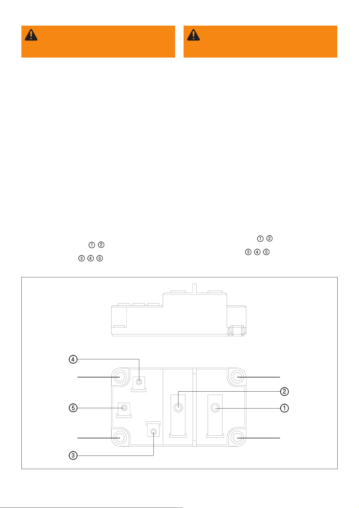
Für die elektrischen Anschlüsse (Abb. 1) gelten folgende
Drehmomentwerte, welche ebenfalls genau einzuhalten sind:
Hochstromanschlüsse Pos.
Steueranschlüsse Pos.
, mindestens 4,0 Nm
maximal 5,0 Nm
, , mindestens 1,5 Nm
maximal 2,0 Nm
Installation procedure:
To ensure a troublefree working of the transistor, the
following installing instructions must be observed with
accuracy and in the order indicated.
1) Remove metal chippings from the mounting surface of the
cooling unit.
Make sure that the drilling holes are deburred properly.
Check the surface for possible damaging caused by
external mechanical impact.
2) Coat the mounting surface of the cooling body with unsoiled
heat conduction paste thinly and evenly.
3) Mount the transistor module correctly.
4) Pass the 4 fastening screws (M6) through the fastening
holes of the transistor module, screwing them slightly into
the cooling body.
5) Tighten the mounting screws by means of a torque wrench
in the order shown in the drawing.
Important! The required torque must be strictly observed!
minimum 5,0 Nm
maximum 6,0 Nm
6) At the end of approx. 30 minutes, retighten the screws once
more as indicated in point 5.
For the electrical connections (fig. 1), the following torques
apply - they also have to be observed carefully:
High current connections pos.
Control connections pos.
, minimum 4,0 Nm
maximum 5,0 Nm
, , minimum 1,5 Nm
maximum 2,0 Nm
2
4
Abb.1 Transistormodul
Fig.1 Transistor module
3
1
1
Page 4

FRONIUS INTERNATIONAL GMBH
Buxbaumstraße 2, A-4600 Wels, Austria
Tel: +43 (0)7242 241-0, Fax: +43 (0)7242 241-3940
E-Mail: sales@fronius.com
www.fronius.com
Under http://www.fronius.com/addresses you will find all addresses
www.fronius.com/addresses
of our Sales & service partners and Locations.
ud_fr_st_so_00082 012008
 Loading...