

Operating
manuals.fronius.com/
html/4204260459
e-Manual
Instructions
MTG Exento
MTW Exento
EN-US
Operating instructions
42,0426,0459,EA 005-21092022


Table of contents
Safety, information on correct use 5
Safety 7
Safety 7
Intended use, requirements for the extraction system 8
Intended use 8
Requirements for the extraction system 8
Extraction information on the rating plate 10
Available interfaces, functions of the torch trigger 11
Available interfaces 13
Up/Down-function 13
JobMaster-function 13
Functions of the torch trigger 14
Functions of the two-staged torch trigger 14
Commissioning 15
Commissioning procedure 17
Procedure for commissioning welding torches with Fronius System Connector 17
Procedure for commissioning welding torches with Euro connection 17
Fitting inner liner in welding torch with Fronius System Connector 18
Note on inner liner in gascooled welding torches 18
Fitting the inner liner 19
Fitting steel inner liner in welding torch with Euro connection 23
Fitting the steel inner liner 23
Fitting plastic inner liner in welding torch with Euro connection 27
Note on inner liner in gascooled welding torches 27
Fitting the plastic inner liner 28
Connecting welding torches to devices with Fronius System Connector 31
Connecting the welding torch to the power source 31
Connecting the welding torch to the wirefeeder 32
Connecting welding torches to devices with Euro connection 33
Connecting the welding torch 33
Connecting welding torch to extraction system and measuring extraction capacity 34
Connecting the welding torch to the extraction system 34
Measuring the extraction capacity (extraction volumetric flow) with the Exentometer 34
Adjusting the extraction capacity 37
Setting the extraction capacity on the welding torch 37
Setting extraction capacity with external air flow regulator 39
EN-US
Fault diagnosis, troubleshooting, maintenance 41
Troubleshooting 43
Troubleshooting 43
Maintenance 49
Detecting defective wear parts 49
Maintenance at the beginning of each working day 50
Maintenance every 48 hours 51
Maintenance at every wirespool/basket-type spool replacement 52
Technical data 55
Technical data of water-cooled welding torches 57
General 57
MTW Exento welding torch technical data 57
Technical data of gascooled welding torches 61
General 61
MTG Exento welding torch technical data 61
3

4

Safety, information on correct use
5

6
Safety
EN-US
Safety
WARNING!
Danger from incorrect operation and work that is not carried out properly.
This can result in serious personal injury and damage to property.
All the work and functions described in this document must only be carried
▶
out by technically trained and qualified personnel.
Read and understand this document in full.
▶
Read and understand all safety rules and user documentation for this equip-
▶
ment and all system components.
WARNING!
Danger from electrical current.
This can result in serious personal injury and damage to property.
Before starting work, switch off all the devices and components involved and
▶
disconnect them from the grid.
Secure all devices and components involved so they cannot be switched back
▶
on.
WARNING!
Danger due to emerging wire electrode.
Serious personal injuries may result.
Hold the welding torch so that the tip of the welding torch points away from
▶
the face and body.
Wear suitable protective goggles.
▶
Do not point the welding torch at people.
▶
Ensure that the wire electrode can only intentionally make contact with elec-
▶
trically conductive objects.
WARNING!
Danger due to hot system components and/or equipment.
This can result in serious burns or scalding.
Before starting work, allow all hot system components and/or equipment to
▶
cool to +25°C/+77°F (e.g., coolant, water-cooled system components,
wirefeeder drive motor, etc.).
Wear suitable protective equipment (e.g., heat-resistant gloves, safety
▶
goggles, etc.) if cooling down is not possible.
WARNING!
Danger from contact with toxic welding fumes.
Serious personal injuries may result.
Welding is not permitted without an extraction unit being switched on.
▶
It may not be sufficient to only use a fume extraction torch to reduce the
▶
concentration of noxious substances at the work station. In this case, install
an additional extraction system to properly reduce the concentration of noxious substances at the work station.
In case of doubt, the concentration of noxious substances at the work sta-
▶
tion should be assessed by a safety engineer.
7

Intended use, requirements for the extraction
system
Intended use The MIG/MAG manual welding torch is intended exclusively for MIG/MAG weld-
ing in conjunction with a sufficiently powerful extraction system (see section Re-
quirements for the extraction system from page 8). Any other use is deemed
to be "not in accordance with the intended purpose." The manufacturer accepts
no liability for any damage resulting from improper use.
Intended use also means:
Reading these Operating Instructions in their entirety
-
Following all instructions and safety rules in this document
-
Carrying out all the specified inspection and maintenance work
-
Requirements
for the extraction system
Only operate Schweißbrenner with extraction systems that meet the following
requirements:
-
Extraction capacity (extraction volumetric flow) of at least 70 - 110 m3/h
(2472 - 3885 cfh); depending on the welding torch used
if the value is lower, there is a risk that the welding fumes will not be ad-
-
equately extracted
a higher value means there is a risk that shielding gas will be unintention-
-
ally sucked off the weld seam
Depending on the length of the extraction hose and the welding torch used, a
-
negative pressure of at least 10 - 18 kPa (100 - 180 mbar) must be generated
the shorter and thicker the extraction hose, the smaller the extraction
-
unit can be dimensioned / the less extraction capacity must be provided
to ensure that the welding fumes are optimally extracted
When the altitude increases, the extraction capacity must be reduced ac-
-
cording to the altitude due to the changing environmental conditions (lower
air pressure, etc.), for example by opening the air flow regulator of the welding torch or reducing the extraction capacity
in any case, the requirements for extraction must be met
-
use the Exentometer to determine the current extraction volumetric flow
-
of the welding torch - for this, see section Measuring the extraction ca-
pacity (extraction volumetric flow) with the Exentometer from page 34
The exact requirements for extraction can be found on the rating plate of the respective welding torch (see section Extraction information on the rating plate on
page 10) and in the technical data.
8
Rating plate on the welding torch
EN-US
9

Extraction in-
∆
p
c
[kPa]
Check
Qv,c [m³/h] Qv,n [m³/h]
11,0 94 57
MIXED
CO2
I2
X (40°C)
EN IEC 60974-7/-10 Cl.A
EN ISO 21904-1
Charge No.
Art.No.
Type
www.fronius.com
Q
v,n
Q
v,c
pc
pc
formation on the
rating plate
Example of a rating plate
Extraction information on the rating plate
Extraction volumetric flow at the front end of the welding torch ( =
the extraction volumetric flow provided by the welding torch)
Extraction volumetric flow at the extraction connection of the welding torch ( = the extraction volumetric flow that the extraction system must provide)
Required negative pressure at the extraction connection of the welding torch (= the negative pressure that the extraction system must
generate)
10

Available interfaces, functions of
the torch trigger
11

12

Available interfaces
EN-US
Up/Down-function
JobMaster-function
The Up/Down torch has the following
functions:
Changing the welding power in
-
synergic operation by means of up/
down buttons
Error display:
-
in the event of a system error,
-
all the LEDs turn red
in the event of a data commu-
-
nication error, all the LEDs
flash red.
Self-testing in the start-up se-
-
quence:
all the LEDs briefly light up in
-
succession.
The JobMaster welding torch has the
following functions:
The desired parameters are chosen
-
via arrow keys at the power source
Use the +/- keys to change the se-
-
lected parameters
The display shows the current
-
parameters and value
13
Functions of the torch trigger
Functions of the
two-staged
torch trigger
Function of the torch trigger at switch position 1 (torch trigger pushed halfway down) = LED lights up
NOTE!
An LED on the welding torch does not work for welding torches with optional
top torch trigger.
14
Function of the torch trigger in switch position 2 (torch trigger pressed all the way down) = LED goes
out, welding process starts

Commissioning
15

16

Commissioning procedure
EN-US
Procedure for
commissioning
welding torches
with Fronius
System Connector
Procedure for
commissioning
welding torches
with Euro connection
Perform the following activities for the correct commissioning of the welding
torch:
Fit the inner liner - Description from page 18
1
Connect the welding torch
2
Description of power source from page 31
-
Description of wirefeeder from page 32
-
Connect the welding torch to the extraction system - Description from page
3
34
Measure extraction capacity - Description from page 34
4
If necessary, adjust the extraction capacity:
Set the extraction capacity directly on the welding torch - Description from
5
page 37
Set the extraction capacity with external air flow regulator - Description
6
from page 39
Perform the following activities for the correct commissioning of the welding
torch:
Fit the inner liner
1
Description of steel inner liner from page 23
-
Description of plastic inner liner from page 27
-
Connect the welding torch to the power source - Description from page 33
2
Connect the welding torch to the extraction system - Description from page
3
34
Measure extraction capacity - Description from page 34
4
If necessary, adjust the extraction capacity:
Set the extraction capacity directly on the welding torch - Description from
5
page 37
Set the extraction capacity with external air flow regulator - Description
6
from page 39
17
Fitting inner liner in welding torch with Fronius
System Connector
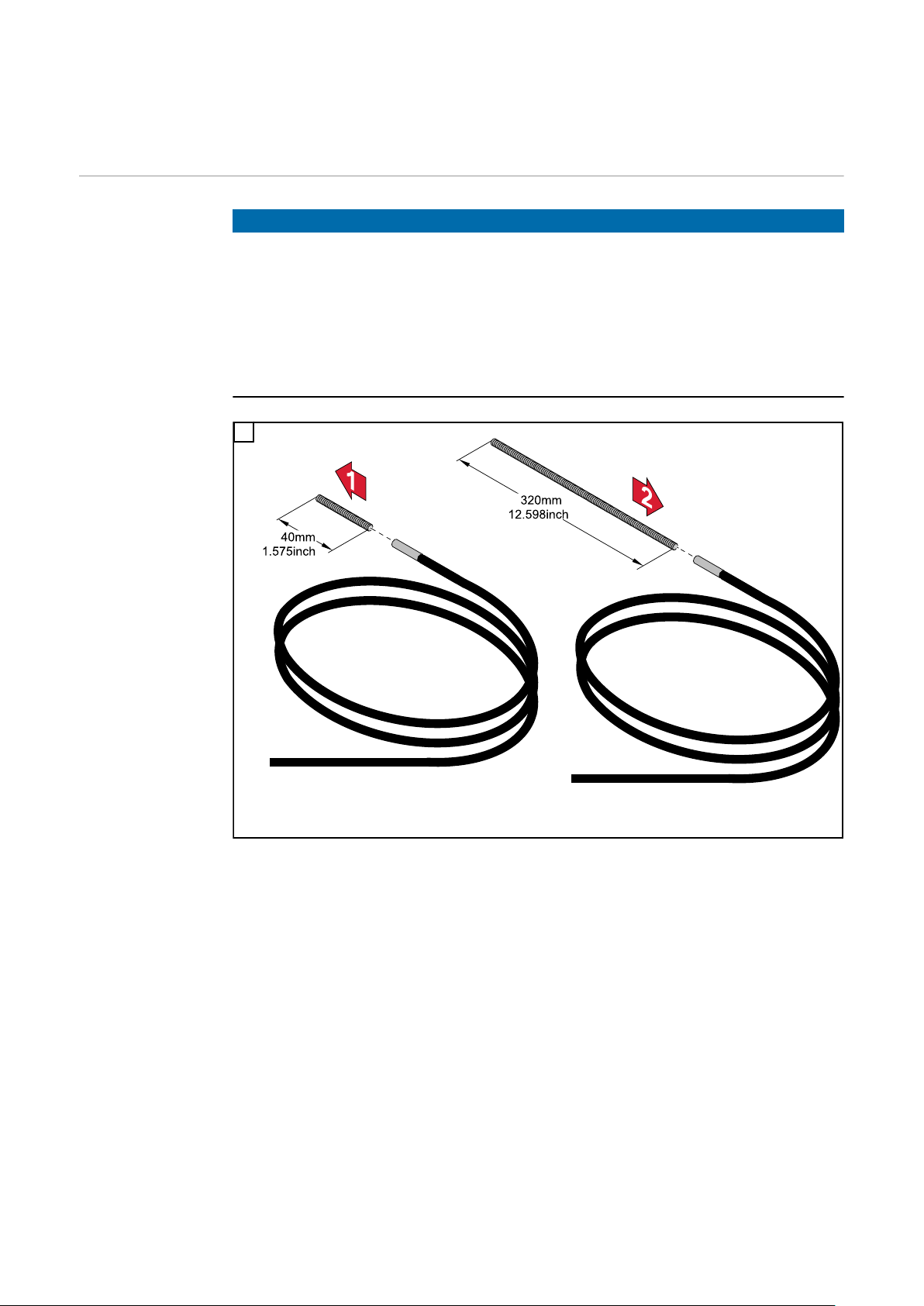
Note on inner
liner in gascooled welding
torches
NOTE!
Risk due to incorrect wire-guide insert.
This can result in poor-quality weld properties.
If a plastic inner liner with a bronze wire-guide insert is used in gascooled
▶
welding torches instead of a steel inner liner, the power data stated in the
technical data of the welding torch must be reduced by 30%.
In order to operate gascooled welding torches at maximum power, replace
▶
the 40 mm (1.575 in.) wire-guide insert with a 320 mm (12.598 in.) wire-guide
insert.
1
18
Fitting the inner
liner
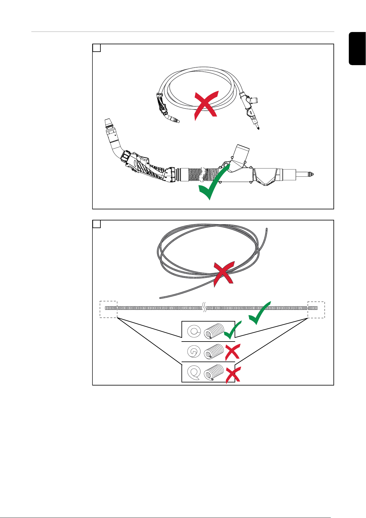
1
EN-US
Lay out the welding torch straight
2
Lay out the inner liner straight; make sure that no burr protrudes into or out of the inner liner
19
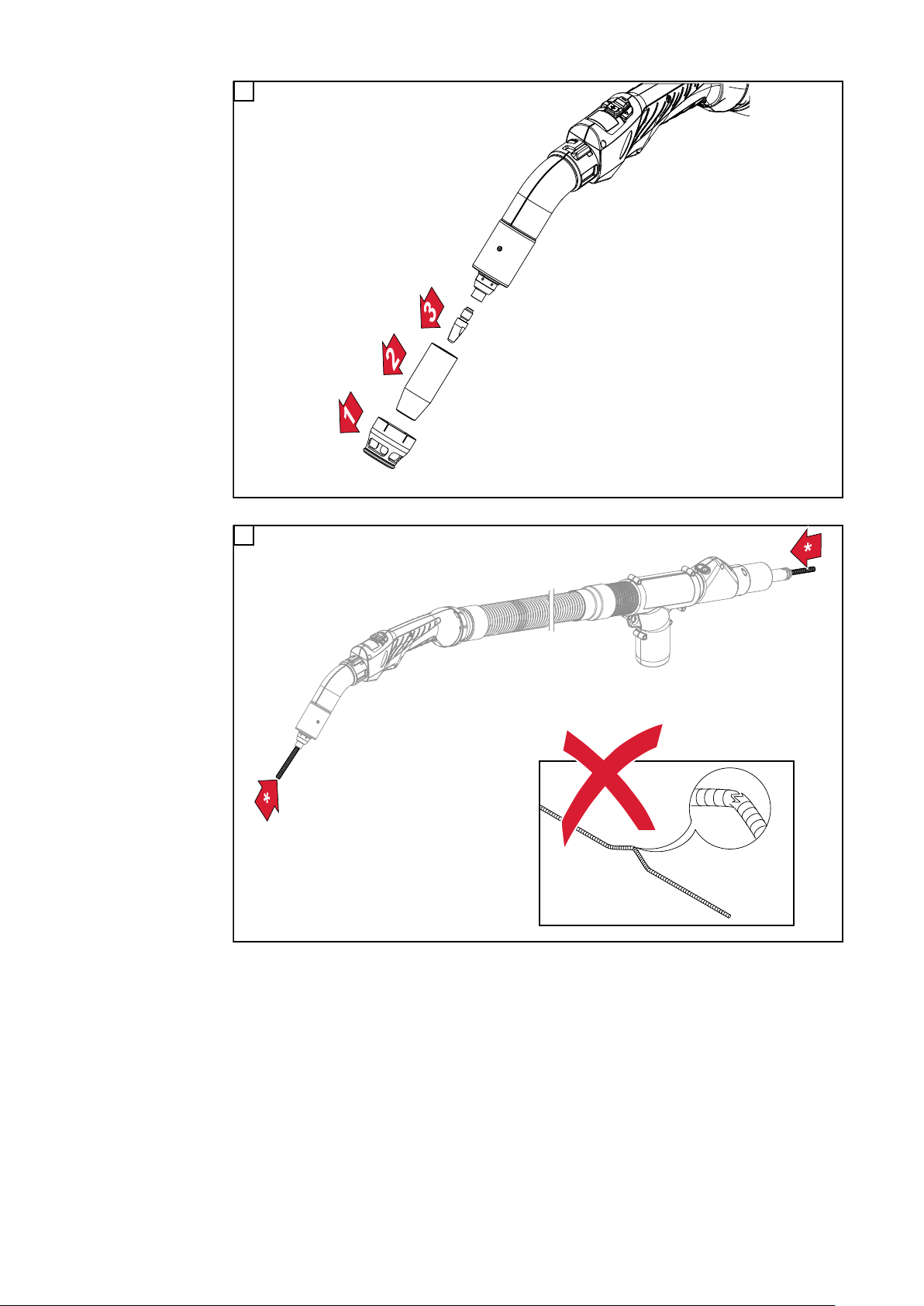
3
If the extraction nozzle, gas nozzle, and contact tip are already mounted, remove them
4
20
Push the inner liner into the welding torch (*this can be done from both sides) until it protrudes from
the front and rear of the welding torch; make sure that the inner liner is not kinked or snapped
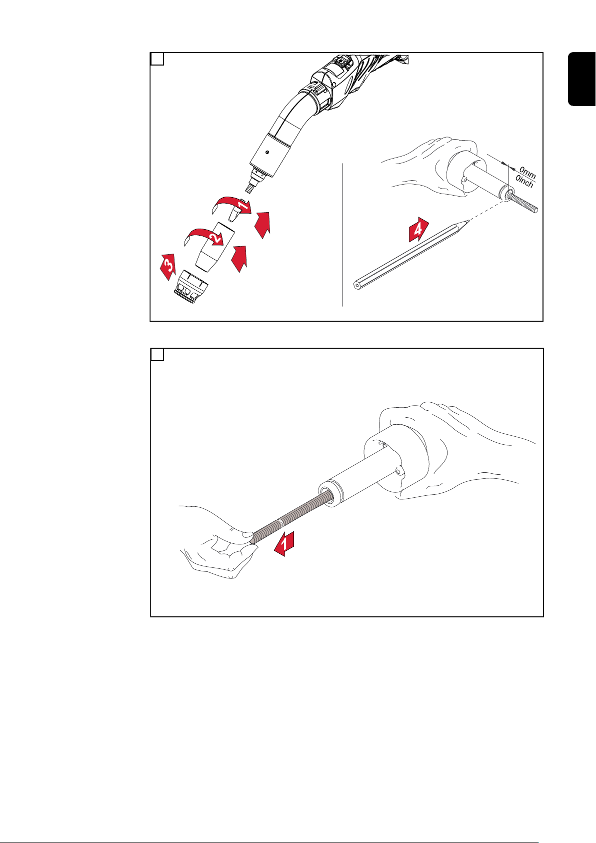
5
Push the inner liner with the contact tip back into the torch body; mount the contact tip, gas nozzle,
and extraction nozzle; mark the inner liner at the end of the Schweißbrenners
6
EN-US
Pull inner liner 10 cm (3.94 in.) out of the welding torch
21

7
Left inner liner made of steel, right plastic: Cut and deburr the inner liner at the previously marked
position; make sure that no burr protrudes into or out of the inner liner
8
22
Screw the cap onto the inner liner up to the stop (the inner liner needs to be visible through the hole
in the cap); push the cap into the welding torch and secure

Fitting steel inner liner in welding torch with Euro
connection
Fitting the steel
inner liner
EN-US
1
Lay out the welding torch straight
2
Lay out the inner liner straight; make sure that no burr protrudes into or out of the inner liner
23

3
If already mounted, remove the extraction nozzle, gas nozzle, contact tip, and cap from the Euro
connection
4
24
Push the inner liner into the welding torch (*this can be done from both sides) until it protrudes from
the front and rear of the welding torch; make sure that the inner liner is not kinked or snapped

5
Push the inner liner with the contact tip back into the torch body; mount the contact tip, gas nozzle,
and extraction nozzle; mark the inner liner at the end of the welding torch
6
EN-US
Pull inner liner 10 cm (3.94 in.) out of the welding torch, cut, and deburr; make sure that no burr protrudes into or out of the inner liner
25

7
Screw the cap onto the inner liner up to the stop; screw the cap into the welding torch
26

Fitting plastic inner liner in welding torch with
Euro connection
Note on inner
liner in gascooled welding
torches
NOTE!
Risk due to incorrect wire-guide insert.
This can result in poor-quality weld properties.
If a plastic inner liner with a bronze wire-guide insert is used in gascooled
▶
welding torches instead of a steel inner liner, the power data stated in the
technical data of the welding torch must be reduced by 30%.
In order to operate gascooled welding torches at maximum power, replace
▶
the 40 mm (1.575 in.) wire-guide insert with a 320 mm (12.598 in.) wire-guide
insert.
1
EN-US
27

Fitting the
plastic inner
liner
1
Lay out the welding torch straight
2
28
Lay out the inner liner straight; ensure that no burr protrudes into or out of the wire-guide insert

3
If already mounted, remove the extraction nozzle, gas nozzle, contact tip, and cap from the Euro
connection
4
EN-US
Push the inner liner into the welding torch (*this can be done from both sides) until it protrudes from
the front and rear of the welding torch; make sure that the inner liner is not kinked or snapped
29

5
Push the inner liner with the contact tip back into the torch body; mount the contact tip, gas nozzle,
and extraction nozzle; secure the inner liner in the welding torch
Refer to the user documentation of the wirefeeder / power source used for
6
instructions on how to correctly cut the inner liner to length
30

Connecting welding torches to devices with Fronius System Connector
Connecting the
welding torch to
the power source
1
EN-US
2
* only with water-cooled welding torches
31

3
Connecting the
welding torch to
the wirefeeder
1
* only with water-cooled welding torches
32

Connecting welding torches to devices with Euro
connection
Connecting the
welding torch
EN-US
1
* only with water-cooled welding torches; connect welding torch to the cooling
unit
** the control line must be provided with the required control plug by the customer. The installer is responsible for the correct execution of the work.
33

Connecting welding torch to extraction system
and measuring extraction capacity
Connecting the
welding torch to
the extraction
system
The welding torch can be connected to an external extraction unit as well as to a
central extraction system. The welding torch is always connected in the same way.
1
Measuring the
extraction capacity (extraction
volumetric flow)
with the Exentometer
Connecting welding torch to external extraction unit
* Recommendations for the extraction hose:
Use Fronius extraction hoses. The design and material composition of Froni-
-
us extraction hoses ensure maximum compatibility and leak-tightness
Keep the extraction hose as short as possible; the shorter the extraction
-
hose, the less energy the extraction unit has to apply to achieve the required
extraction values (for more information on the required extraction values, see
section Requirements for the extraction system from page 8 and technical
data)
The extraction volumetric flow is used as a measured value for the extraction capacity of the welding torch. The extraction volumetric flow is measured with the
Exentometer .
Measure the extraction capacity (extraction volumetric flow):
Switch on the extraction system
1
Read off the required extraction volumetric flow (Q
2
the welding torch - see also Extraction information on the rating plate on
page 10) or in the technical data
Ensure that the welding torch (including hosepack) and the extraction hose
3
do not have any holes, cracks, or other damage
Ensure that external adjustment devices do not falsify the check of the ex-
4
traction capacity (for example, external air flow regulators - see section Set-
ting extraction capacity with external air flow regulator from page 39, ....)
) - on the rating plate of
v,n
34

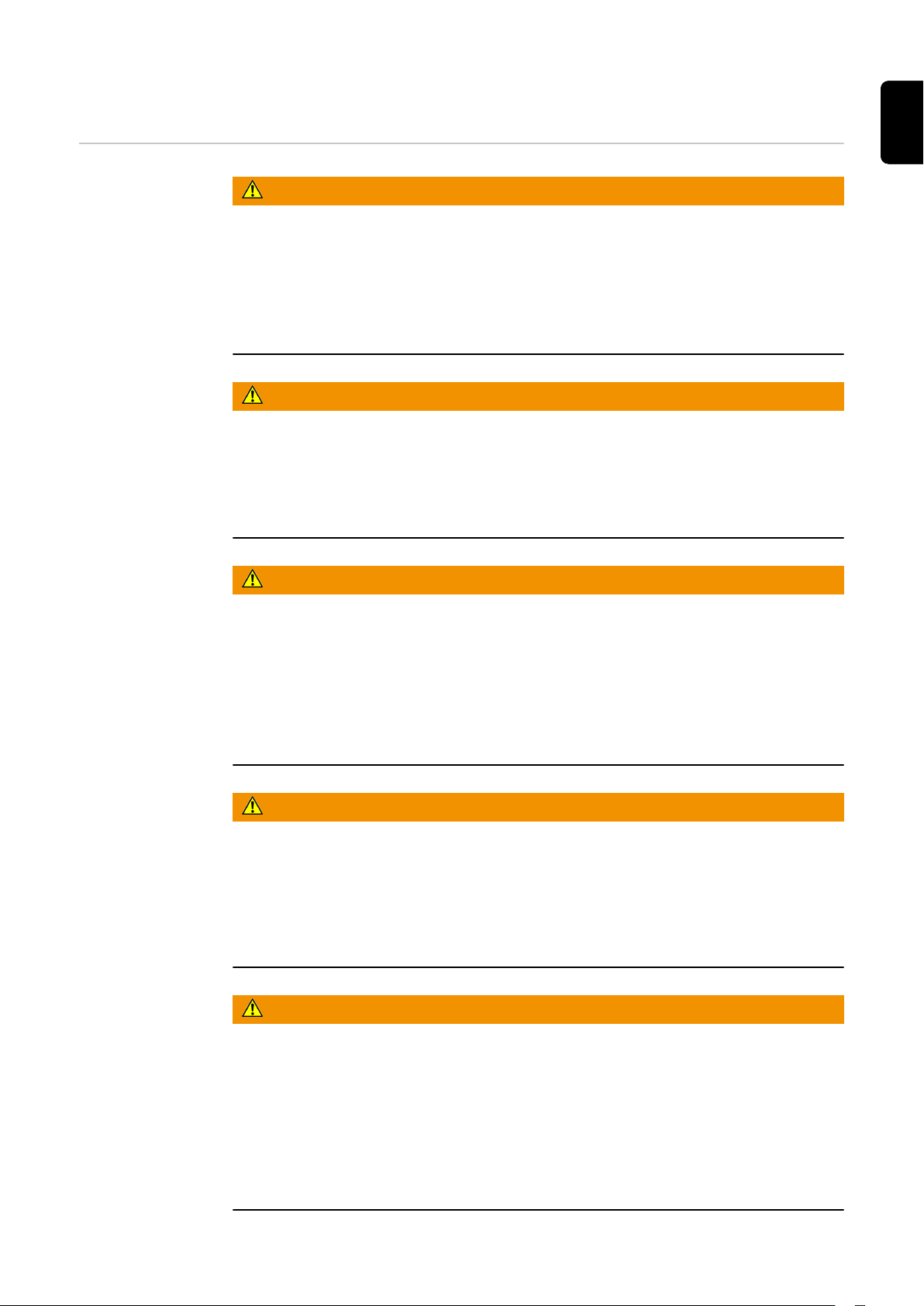
Remove the extraction nozzle and close the air flow regulator - see the figure
5
below
EN-US
Removing extraction nozzle and closing air flow regulator
Place the Exentometer upright on a solid surface (for example, on a work-
6
bench)
Insert the welding torch into the Exentometer as far as it will go
7
Since the extraction system is already running, the Exentometer immedi-
-
ately displays the current extraction capacity
* Ensure that the welding torch is fully inserted into the Exentometer and
8
that no air can escape between the welding torch and the Exentometer
This ensures that the displayed value for the extraction capacity is not
-
distorted
Putting welding torch in the Exentometer
35

Compare the measured extraction volumetric flow with the required extrac-
9
tion volumetric flow
if the two values match, no further measures are necessary
-
if the two values do not match, increase or reduce the power of the ex-
-
traction system until the extraction volumetric flow is in the correct
range
if the extraction volumetric flow is too low, there is a risk that the
-
welding fumes will not be optimally extracted
an excessively high extraction volumetric flow means there is a risk
-
that shielding gas will be unintentionally sucked off the weld seam
36

Adjusting the extraction capacity
EN-US
Setting the extraction capacity
on the welding
torch
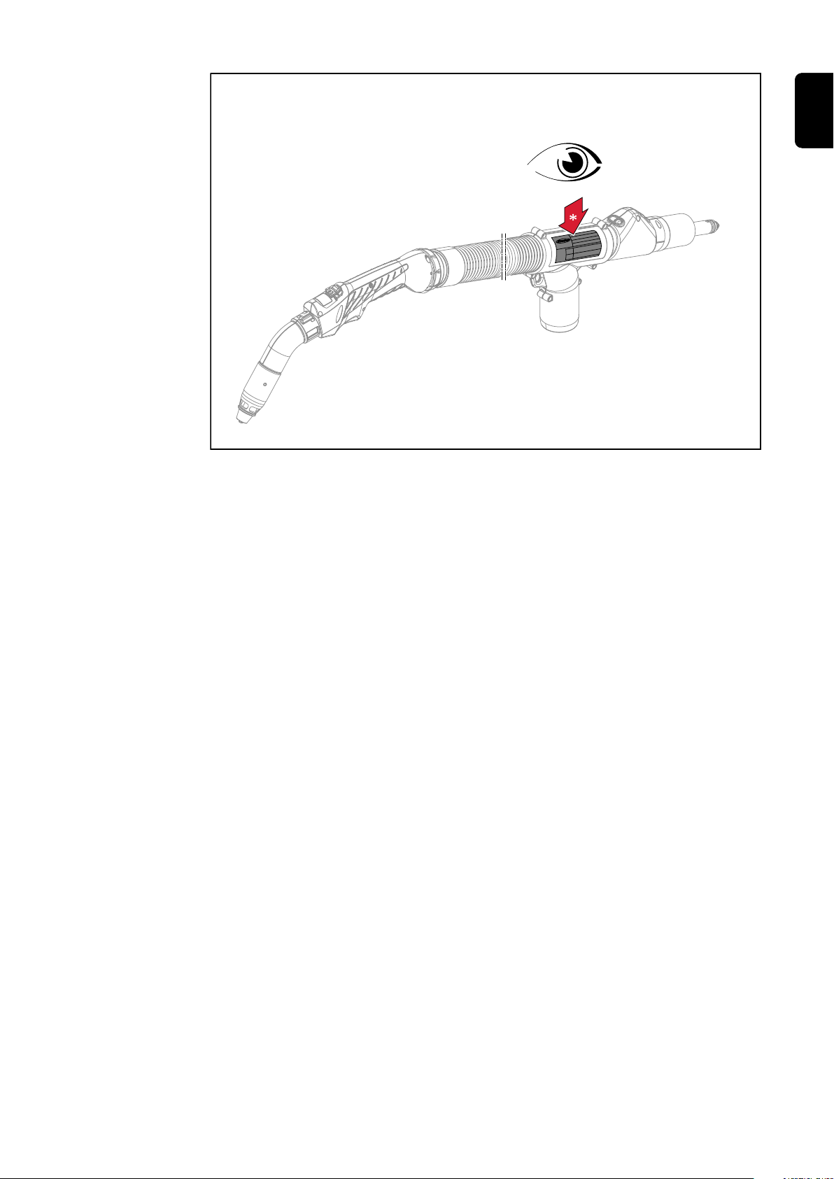
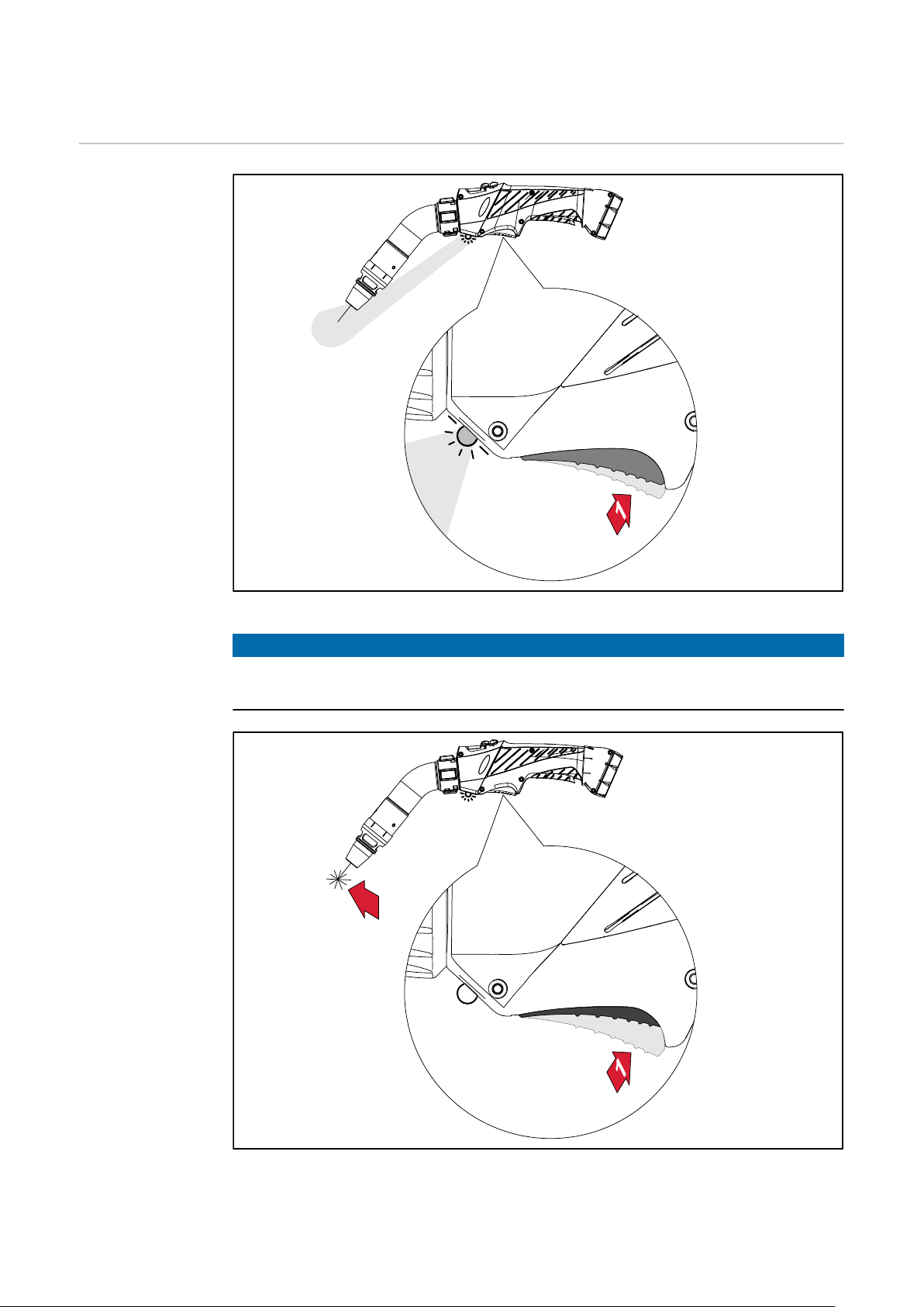
The air flow regulator can be opened to reduce the extraction capacity. If the air
flow regulator is fully open, this reduces the extraction capacity of the welding
torch by 40%.
1
Left: air flow regulator closed = extraction capacity 100%; right: air flow regulator open = extraction
capacity 60%
Applications of the air flow regulator:
When welding in corners or fillet welds, it is possible for the welding fumes to
-
be optimally extracted even with reduced extraction capacity
In this case, too high an extraction capacity could lead to unintentional ex-
-
traction of the shielding gas
In this case, it is recommended to open the air flow regulator and thereby re-
-
duce the extraction capacity
37

Welding of a fillet weld; air flow regulator open = extraction capacity reduced
When welding on open surfaces (such as square butt welds), it may be necessary
to close the air flow regulator and thus use the maximum extraction capacity.
This provides the best possible extraction of welding fumes.
38
Welding of a square butt weld; air flow regulator closed = maximum extraction capacity
WARNING!
Danger from contact with toxic welding fumes.
Serious personal injuries may result.
Always ensure that all welding fumes are extracted, regardless of the welding
▶
task.

Setting extraction capacity
with external air
flow regulator
Particularly in the case of central extraction systems, it may be necessary to adjust the extraction capacity manually using the optionally available external air
flow regulator:
by completely opening the external air flow regulator, the air flow remains al-
-
most unchanged
by completely closing the external air flow regulator, the air flow is reduced
-
to a minimum level
1
EN-US
(1) central extraction system, (2) extraction hose, (3) external air flow regulator, (4) welding torch
After adjusting the air flow, always measure the extraction capacity of the
2
welding torch - for this, see section Measuring the extraction capacity (ex-
traction volumetric flow) with the Exentometer from page 34
39

40

Fault diagnosis, troubleshooting,
maintenance
41

42

Troubleshooting
EN-US
Troubleshooting
Porosity of weld seam
Cause:
Remedy:
Extraction too low
Cause:
Remedy:
Cause:
Remedy:
Cause:
Remedy:
Cause:
Remedy:
No welding current
Power source switched on, power source indication illuminates, shielding gas
present
Cause:
Remedy:
Extraction too strong
Reduce extraction
Holes in the extraction hose
Replace extraction hose
Displaced extraction unit filter
Replace extraction unit filter
Air passages otherwise blocked
Remove blockages
Extraction capacity of extraction unit too low
Use extraction unit with higher extraction capacity
Incorrect ground connection
Establish proper ground connection
Cause:
Remedy:
No shielding gas
All other functions present
Cause:
Remedy:
Cause:
Remedy:
Cause:
Remedy:
Cause:
Remedy:
Cause:
Remedy:
Power cable in welding torch damaged or broken.
Replace welding torch
Gas cylinder empty
Change gas cylinder
Gas pressure regulator faulty
Replace gas pressure regulator
Gas hose kinked, damaged, or not attached
Attach and straighten gas hose. Replace faulty gas hose
Welding torch faulty
Replace welding torch
Gas solenoid valve faulty
Contact service team (have gas solenoid valve replaced)
43

No function after pressing torch trigger
Power source switched on, power source indication illuminates
Cause:
Remedy:
Cause:
Remedy:
Cause:
Remedy:
Cause:
Remedy:
FSC (‘Fronius System Connector’—central connector) not inserted
up to the stop
Insert FSC up to the stop
Welding torch or welding torch control line faulty
Replace welding torch
Interconnecting hosepack not properly connected or faulty
Connect interconnecting hosepack properly
Replace faulty interconnecting hosepack
Faulty power source
Notify service provider
44

Poor-quality weld properties
Cause:
Remedy:
Incorrect welding parameters
Correct settings
EN-US
Cause:
Remedy:
Cause:
Remedy:
Cause:
Remedy:
Cause:
Remedy:
Cause:
Remedy:
Cause:
Remedy:
Cause:
Remedy:
Poor ground earth connection
Establish good contact with workpiece
Too little or no shielding gas
Check pressure regulator, gas hose, gas solenoid valve and welding
torch gas connection. For gas-cooled welding torches, check gas seal,
use suitable inner liner
Welding torch leaks
Replace welding torch
Excessively large or heavily worn contact tip
Change contact tip
Incorrect wire alloy or incorrect wire diameter
Check the inserted wire spool/basket-type spool
Incorrect wire alloy or incorrect wire diameter
Check the weldability of the parent materials
Shielding gas not suitable for wire alloy
Use correct shielding gas
Cause:
Remedy:
Cause:
Remedy:
Cause:
Remedy:
Cause:
Remedy:
Cause:
Remedy:
Cause:
Remedy:
Unfavorable welding conditions: Shielding gas contaminated (moisture, air), inadequate gas shield (weld pool “boiling”, draft), impurities
in the workpiece (rust, paint, grease)
Optimize welding conditions
Welding spatter in the gas nozzle
Remove welding spatter
Turbulence due to excessively high quantity of shielding gas
Reduce quantity of shielding gas; recommended:
shielding gas quantity (l/min) = wirespool diameter (mm) x 10
(for example 16 l/min for 1.6 mm wire electrode)
Excessively large distance between welding torch and workpiece
Reduce distance between welding torch and workpiece (approx. 10–
15 mm/0.39–0.59 in.)
Excessively large work angle of the welding torch
Reduce work angle of the welding torch
Wirefeed components do not correspond to the diameter of the wire
electrode/the material of the wire electrode
Use correct wirefeed components
45

Poor wirefeeding
Cause:
Remedy:
Depending on the system, brakes in the wirefeeder or power source
set too tightly
Set the brakes to be looser
Cause:
Remedy:
Cause:
Remedy:
Cause:
Remedy:
Cause:
Remedy:
Cause:
Remedy:
Cause:
Remedy:
Cause:
Remedy:
Hole in the contact tip displaced
Replace contact tip
Faulty inner liner or wire-guide insert
Check inner liner or wire-guide insert for kinks, soiling, etc.
Replace faulty inner liner or wire-guide insert
Feed rollers not suitable for wire electrode used
Use suitable feed rollers
Incorrect contact pressure of the feed rollers
Optimize contact pressure
Feed rollers soiled or damaged
Clean or replace feed rollers
Inner liner displaced or kinked
Replace inner liner
Inner liner too short after cutting to length
Replace inner liner and cut new inner liner to correct length
Cause:
Remedy:
Cause:
Remedy:
Cause:
Remedy:
Gas nozzle gets very hot
Cause:
Remedy:
Wear of the wire electrode due to excessive contact pressure from
the feed rollers
Reduce contact pressure from the feed rollers
Wire electrode soiled or rusted
Use high-quality wire electrode without soiling
For steel inner liners: use of uncoated inner liner
Use a coated inner liner
No heat dissipation due to gas nozzle being fitted too loosely
Screw the gas nozzle tightly up to the stop
46

Welding torch gets very hot
Cause:
Remedy:
Only in multi-lock welding torches: Union nut of the torch body loose
Tighten union nut
EN-US
Cause:
Remedy:
Cause:
Remedy:
Cause:
Remedy:
Cause:
Remedy:
Short service life of the contact tip
Cause:
Remedy:
Cause:
Remedy:
Welding torch has been operated above the maximum welding current
Reduce welding power or use more powerful welding torch
Welding torch is inadequately sized
Observe duty cycle and load limits
For water-cooled systems only: Coolant flow too low
Check coolant level, coolant flow, coolant contamination, displace-
ment of the hosepack, etc.
Tip of the welding torch too close to the arc
Increase stick out
Incorrect feed rollers
Use correct feed rollers
Wear of the wire electrode due to excessive contact pressure at the
feed rollers
Reduce contact pressure at the feed rollers
Cause:
Remedy:
Cause:
Remedy:
Cause:
Remedy:
Cause:
Remedy:
Cause:
Remedy:
NOTE!
In CrNi applications, greater contact tip wear may occur due to the surface finish of the CrNi wire electrode.
Wire electrode soiled/rusted
Use high-quality wire electrode without soiling
Uncoated wire electrode
Use wire electrode with suitable coating
Incorrect dimensions of the contact tip
Use contact tip of the correct size
Duty cycle of the welding torch too long
Reduce duty cycle or use more powerful welding torch
Contact tip overheats. No heat dissipation due to contact tip being
fitted too loosely
Tighten contact tip
47

Malfunction of the torch trigger
Cause:
Remedy:
Faulty plug connections between the welding torch and the power
source
Establish correct plug connections/send power source or welding
torch to service team
Cause:
Remedy:
Cause:
Remedy:
Porosity of weld seam
Cause:
Remedy:
Cause:
Remedy:
Cause:
Remedy:
Cause:
Remedy:
Cause:
Remedy:
Soiling between torch trigger and torch trigger housing
Remove soiling
Faulty control line
Notify service provider
Spattering in the gas nozzle, causing inadequate gas shield for weld
seam
Remove welding spatter
Holes in gas hose or imprecise gas hose connection
Replace gas hose
O-ring at central connector is cut or faulty
Replace O-ring
Moisture/condensate in the gas line
Dry gas line
Gas flow too strong or weak
Correct gas flow
Cause:
Remedy:
Cause:
Remedy:
Cause:
Remedy:
Cause:
Remedy:
Inadequate quantity of gas at the start or end of welding
Increase gas pre-flow and gas post-flow
Rusted or poor quality wire electrode
Use high-quality wire electrode without soiling
Applies to gas-cooled welding torches: Gas leakage with non-isolated
inner liners
For gas-cooled welding torches, only use isolated inner liners
Too much parting agent applied
Remove excess parting agent/apply less parting agent
48

Maintenance
Detecting defective wear
parts
1.
2.
3.
4.
5.
6.
Nozzle fitting
Burnt outer edges, notches
-
Heavily coated with welding spatter
-
Spatter guard (only for water-cooled welding torches)
Burnt outer edges, notches
-
Extraction nozzle
Burnt outer edges, notches
-
Contact tip
Ground (oval) wire entry and wire exit bores
-
Heavily coated with welding spatter
-
Penetration at the tip of the contact tip
-
Gas nozzle
Heavily coated with welding spatter
-
Burnt outer edges
-
Notches
-
Insulating parts
Burnt outer edges, notches
-
EN-US
49

Maintenance at
the beginning of
each working day
Check extraction nozzle and replace if damaged:
1
Clean gas nozzle, contact tip, spatter guard (only for water-cooled welding
torches), nozzle fitting, and insulating parts from welding splatter, check for
damage, and replace damaged parts:
2
50
In addition to the steps listed above, prior to starting up water-cooled weld-
3
ing torches always:
Ensure that all coolant connections are leak-tight
-
Ensure that there is a proper coolant return flow - refer to the user docu-
-
mentation of the cooling unit for more information

Maintenance
every 48 hours
Open and close the air flow regulator every 48 hours:
Switch on the extraction system
1
2
EN-US
Opening and closing the air flow regulator
If the air inlets are dirty and / or the air flow regulator can no longer be opened
smoothly, clean the air inlets with compressed air:
3
Ensure that any particles released during cleaning are picked up by the extraction system
51

Maintenance at
every wirespool/
basket-type
spool replacement
Clean the wirefeeding hose with reduced compressed air:
1
Dismantling the wearing parts
Switch on the extraction system
2
3
52
Cleaning the hosepack; ensure that any particles released during cleaning are picked up by the extraction system

Recommended - When replacing the inner liner, clean the wearing parts before
re-installing the inner liner:
4
Cleaning the contact tip, spatter guard, and nozzle fitting with compressed air; ensure that any
particles released during cleaning are picked up by the extraction system
5
EN-US
Cleaning extraction nozzle and gas nozzle with brush
53

54

Technical data
55

56

Technical data of water-cooled welding torches
General Voltage rating (V-peak):
For hand-held welding torches: 113 V
-
For machine-guided welding torches: 141 V
-
Torch trigger technical data:
U
-
-
The torch trigger can only be operated within the limits of the technical data.
This product meets the requirements set out in standard
-
-
The welding fume detection efficiency of torch-integrated extraction systems
(according to EN ISO 21904-3) depends on several influencing factors, such as:
-
-
-
-
-
-
-
-
-
= 5 V
max
I
= 10 mA
max
EN IEC 60974-7 / - 10 CI. A and
EN ISO 21904-1.
Workpiece quality and the associated fume formation during welding
Welding process
Welding direction (trailing or leading)
Welding positions (PA, PC, PF, etc.)
Workpiece geometry (open or closed design, etc.)
Volumetric flow of the shielding gas
Work angle of the welding torch
Environmental conditions
...
EN-US
MTW Exento
welding torch
technical data
MTW 300i Exento | Welding torch length = 3.5 m (11 ft. 5.8 in.)
Welding current at 10 min / 40 °C (104 °F);
100% D.C.1) / 300 A
Values apply with CO2 and mixed gas as shielding gas
(EN ISO 14175)
Extraction volumetric flow at the front end of the welding torch Q
(EN IEC ISO 21904-1)
v,n
Extraction volumetric flow at the extraction connection
of the welding torch Q
(EN IEC ISO 21904-1)
v,c
Required negative pressure Δpc at the extraction con-
52 m3/h (1837 cfh)
95 m3/h (1837 cfh)
13.5 kPa (135 mbar)
nection of the welding torch (EN IEC ISO 21904-1)
Required minimum cooling power according to standard
IEC 60974-2
Required minimum coolant flow Q
min
(0.26 gal. [US]/min)
Required minimum coolant pressure p
Maximum permissible coolant pressure p
min
max
Permissible wire electrodes (diameter)
700 W
1 l/min
3 bar (43 psi)
5.5 bar (79 psi)
0.8 - 1.2 mm
(0.032 - 0.047 in.)
57

MTW 300i Exento | Welding torch length = 4.5 m (14 ft. 9.17 in.)
Welding current at 10 min / 40 °C (104 °F);
100% D.C.1) / 300 A
Values apply with CO2 and mixed gas as shielding gas
(EN ISO 14175)
Extraction volumetric flow at the front end of the welding torch Q
(EN IEC ISO 21904-1)
v,n
Extraction volumetric flow at the extraction connection
of the welding torch Q
(EN IEC ISO 21904-1)
v,c
Required negative pressure Δpc at the extraction con-
52 m3/h (1837 cfh)
100 m3/h (3532 cfh)
15 kPa (150 mbar)
nection of the welding torch (EN IEC ISO 21904-1)
Required minimum cooling power according to standard
IEC 60974-2
Required minimum coolant flow Q
min
(0.26 gal. [US]/min)
Required minimum coolant pressure p
Maximum permissible coolant pressure p
Permissible wire electrodes (diameter)
min
max
(0.032 - 0.047 in.)
MTW 300d Exento | Welding torch length = 3.5 m (11 ft. 5.8 in.)
900 W
1 l/min
3 bar (43 psi)
5.5 bar (79 psi)
0.8 - 1.2 mm
Welding current at 10 min / 40 °C (104 °F);
100% D.C.1) / 300 A
Values apply with CO2 and mixed gas as shielding gas
(EN ISO 14175)
Extraction volumetric flow at the front end of the welding torch Q
(EN IEC ISO 21904-1)
v,n
Extraction volumetric flow at the extraction connection
of the welding torch Q
(EN IEC ISO 21904-1)
v,c
Required negative pressure Δpc at the extraction con-
52 m3/h (1837 cfh)
95 m3/h (1837 cfh)
13.5 kPa (135 mbar)
nection of the welding torch (EN IEC ISO 21904-1)
Required minimum cooling power according to standard
IEC 60974-2
Required minimum coolant flow Q
min
(0.26 gal. [US]/min)
Required minimum coolant pressure p
Maximum permissible coolant pressure p
Permissible wire electrodes (diameter)
min
max
(0.032 - 0.047 in.)
MTW 300d Exento | Welding torch length = 4.5 m (14 ft. 9.17 in.)
700 W
1 l/min
3 bar (43 psi)
5.5 bar (79 psi)
0.8 - 1.2 mm
58
Welding current at 10 min / 40 °C (104 °F);
Values apply with CO2 and mixed gas as shielding gas
(EN ISO 14175)
Extraction volumetric flow at the front end of the welding torch Q
(EN IEC ISO 21904-1)
v,n
Extraction volumetric flow at the extraction connection
of the welding torch Q
(EN IEC ISO 21904-1)
v,c
100% D.C.1) / 300 A
52 m3/h (1837 cfh)
100 m3/h (3532 cfh)

MTW 300d Exento | Welding torch length = 4.5 m (14 ft. 9.17 in.)
Required negative pressure Δpc at the extraction con-
15 kPa (150 mbar)
nection of the welding torch (EN IEC ISO 21904-1)
Required minimum cooling power according to standard
IEC 60974-2
Required minimum coolant flow Q
min
(0.26 gal. [US]/min)
Required minimum coolant pressure p
Maximum permissible coolant pressure p
min
max
Permissible wire electrodes (diameter)
MTW 500i Exento | Welding torch length = 3.5 m (11 ft. 5.8 in.)
Welding current at 10 min / 40 °C (104 °F);
Values apply with CO2 and mixed gas as shielding gas
100% D.C.1) / 400 A
40% D.C.1) / 500 A
(EN ISO 14175)
Extraction volumetric flow at the front end of the welding torch Q
(EN IEC ISO 21904-1)
v,n
Extraction volumetric flow at the extraction connection
of the welding torch Q
(EN IEC ISO 21904-1)
v,c
57 m3/h (2013 cfh)
100 m3/h (3532 cfh)
EN-US
900 W
1 l/min
3 bar (43 psi)
5.5 bar (79 psi)
0.8 - 1.2 mm
(0.032 - 0.047 in.)
Required negative pressure Δpc at the extraction con-
11.9 kPa (119 mbar)
nection of the welding torch (EN IEC ISO 21904-1)
Required minimum cooling power according to standard
IEC 60974-2
Required minimum coolant flow Q
min
(0.26 gal. [US]/min)
Required minimum coolant pressure p
Maximum permissible coolant pressure p
Permissible wire electrodes (diameter)
min
max
(0.039 - 0.063 in.)
MTW 500i Exento | Welding torch length = 4.5 m (14 ft. 9.17 in.)
Welding current at 10 min / 40 °C (104 °F);
Values apply with CO2 and mixed gas as shielding gas
100% D.C.1) / 400 A
40% D.C.1) / 500 A
(EN ISO 14175)
Extraction volumetric flow at the front end of the welding torch Q
(EN IEC ISO 21904-1)
v,n
Extraction volumetric flow at the extraction connection
of the welding torch Q
(EN IEC ISO 21904-1)
v,c
57 m3/h (2013 cfh)
105 m3/h (3709 cfh)
1000 W
1 l/min
3 bar (43 psi)
5.5 bar (79 psi)
1 - 1.6 mm
Required negative pressure Δpc at the extraction connection of the welding torch (EN IEC ISO 21904-1)
Required minimum cooling power according to standard
IEC 60974-2
Required minimum coolant flow Q
Required minimum coolant pressure p
min
min
14 kPa (140 mbar)
1200 W
1 l/min
(0.26 gal. [US]/min)
3 bar (43 psi)
59

MTW 500i Exento | Welding torch length = 4.5 m (14 ft. 9.17 in.)
Maximum permissible coolant pressure p
Permissible wire electrodes (diameter)
max
(0.039 - 0.063 in.)
MTW 500d Exento | Welding torch length = 3.5 m (11 ft. 5.8 in.)
Welding current at 10 min / 40 °C (104 °F);
Values apply with CO2 and mixed gas as shielding gas
100% D.C.1) / 400 A
40% D.C.1) / 500 A
(EN ISO 14175)
Extraction volumetric flow at the front end of the welding torch Q
(EN IEC ISO 21904-1)
v,n
Extraction volumetric flow at the extraction connection
of the welding torch Q
(EN IEC ISO 21904-1)
v,c
Required negative pressure Δpc at the extraction con-
57 m3/h (2013 cfh)
100 m3/h (3532 cfh)
11.9 kPa (119 mbar)
nection of the welding torch (EN IEC ISO 21904-1)
Required minimum cooling power according to standard
IEC 60974-2
Required minimum coolant flow Q
min
(0.26 gal. [US]/min)
Required minimum coolant pressure p
min
5.5 bar (79 psi)
1 - 1.6 mm
1000 W
1 l/min
3 bar (43 psi)
Maximum permissible coolant pressure p
Permissible wire electrodes (diameter)
max
(0.039 - 0.063 in.)
MTW 500d Exento | Welding torch length = 4.5 m (14 ft. 9.17 in.)
Welding current at 10 min / 40 °C (104 °F);
Values apply with CO2 and mixed gas as shielding gas
100% D.C.1) / 400 A
40% D.C.1) / 500 A
(EN ISO 14175)
Extraction volumetric flow at the front end of the welding torch Q
(EN IEC ISO 21904-1)
v,n
Extraction volumetric flow at the extraction connection
of the welding torch Q
(EN IEC ISO 21904-1)
v,c
Required negative pressure Δpc of the extraction sys-
57 m3/h (2013 cfh)
105 m3/h (3709 cfh)
14 kPa (140 mbar)
tem (EN IEC ISO 21904-1)
Minimum cooling power according to standard
IEC 60974-2
Minimum coolant flow Q
min
(0.26 gal. [US]/min)
Minimum coolant pressure p
min
5.5 bar (79 psi)
1 - 1.6 mm
1200 W
1 l/min
3 bar (43 psi)
60
Maximum coolant pressure p
max
Permissible wire electrodes (diameter)
1)
ED = Duty cycle; after-run time of extraction system after end of welding
= 30 seconds
5.5 bar (79 psi)
1 - 1.6 mm
(0.039 - 0.063 in.)

Technical data of gascooled welding torches
General Voltage rating (V-peak):
For hand-held welding torches: 113 V
-
For machine-guided welding torches: 141 V
-
Torch trigger technical data:
U
-
-
The torch trigger can only be operated within the limits of the technical data.
This product meets the requirements set out in standard
-
-
The welding fume detection efficiency of torch-integrated extraction systems
(according to EN ISO 21904-3) depends on several influencing factors, such as:
-
-
-
-
-
-
-
-
-
= 5 V
max
I
= 10 mA
max
EN IEC 60974-7 / - 10 CI. A and
EN ISO 21904-1.
Workpiece quality and the associated fume formation during welding
Welding process
Welding direction (trailing or leading)
Welding positions (PA, PC, PF, etc.)
Workpiece geometry (open or closed design, etc.)
Volumetric flow of the shielding gas
Work angle of the welding torch
Environmental conditions
...
EN-US
MTG Exento
welding torch
technical data
MTG 250i Exento | Welding torch length = 3.5 m (11 ft. 5.8 in.)
Welding current at 10 min / 40 °C (104 °F);
Values apply with CO2 as shielding gas
(EN ISO 14175)
Welding current at 10 min / 40 °C (104 °F);
Values apply with mixed gas as shielding gas
(EN ISO 14175)
Extraction volumetric flow at the front end of the welding torch Q
Extraction volumetric flow at the extraction connection
of the welding torch Q
Required negative pressure Δpc at the extraction connection of the welding torch (EN IEC ISO 21904-1)
Permissible wire electrodes (diameter)
MTG 250i Exento | Welding torch length = 4.5 m (14 ft. 9.17 in.)
Welding current at 10 min / 40 °C (104 °F);
Values apply with CO2 as shielding gas
(EN ISO 14175)
(EN IEC ISO 21904-1)
v,n
(EN IEC ISO 21904-1)
v,c
40% D.C.1) / 250 A
60% D.C.1) / 210 A
100% D.C.1) / 170 A
40% D.C.1) / 250 A
60% D.C.1) / 210 A
100% D.C.1) / 170 A
52 m3/h (1837 cfh)
70 m3/h (2472 cfh)
10 kPa (100 mbar)
(0.032 - 0.047 in.)
40% D.C.1) / 250 A
60% D.C.1) / 210 A
100% D.C.1) / 170 A
0.8 - 1.2 mm
61

MTG 250i Exento | Welding torch length = 4.5 m (14 ft. 9.17 in.)
Welding current at 10 min / 40 °C (104 °F);
Values apply with mixed gas as shielding gas
(EN ISO 14175)
Extraction volumetric flow at the front end of the welding torch Q
(EN IEC ISO 21904-1)
v,n
Extraction volumetric flow at the extraction connection
of the welding torch Q
(EN IEC ISO 21904-1)
v,c
Required negative pressure Δpc at the extraction con-
40% D.C.1) / 250 A
60% D.C.1) / 210 A
100% D.C.1) / 170 A
52 m3/h (1837 cfh)
80 m3/h (2526 cfh)
10.8 kPa (108 mbar)
nection of the welding torch (EN IEC ISO 21904-1)
Permissible wire electrodes (diameter)
MTG 250d Exento | Welding torch length = 3.5 m (11 ft. 5.8 in.)
Welding current at 10 min / 40 °C (104 °F):
Values apply with CO2 as shielding gas
(EN ISO 14175)
Welding current at 10 min / 40 °C (104 °F);
Values apply with mixed gas as shielding gas
(EN ISO 14175)
40% D.C.1) / 250 A
60% D.C.1) / 210 A
100% D.C.1) / 170 A
40% D.C.1) / 200 A
60% D.C.1) / 160 A
100% D.C.1) / 120 A
0.8 - 1.2 mm
(0.032 - 0.047 in.)
Extraction volumetric flow at the front end of the welding torch Q
(EN IEC ISO 21904-1)
v,n
Extraction volumetric flow at the extraction connection
of the welding torch Q
(EN IEC ISO 21904-1)
v,c
Required negative pressure Δpc at the extraction con-
52 m3/h (1837 cfh)
70 m3/h (2472 cfh)
10 kPa (100 mbar)
nection of the welding torch (EN IEC ISO 21904-1)
Permissible wire electrodes (diameter)
(0.032 - 0.047 in.)
MTG 250d Exento | Welding torch length = 4.5 m (14 ft. 9.17 in.)
Welding current at 10 min / 40 °C (104 °F):
Values apply with CO2 as shielding gas
(EN ISO 14175)
Welding current at 10 min / 40 °C (104 °F);
Values apply with mixed gas as shielding gas
(EN ISO 14175)
Extraction volumetric flow at the front end of the welding torch Q
(EN IEC ISO 21904-1)
v,n
Extraction volumetric flow at the extraction connection
of the welding torch Q
(EN IEC ISO 21904-1)
v,c
40% D.C.1) / 250 A
60% D.C.1) / 210 A
100% D.C.1) / 170 A
40% D.C.1) / 200 A
60% D.C.1) / 160 A
100% D.C.1) / 120 A
52 m3/h (1837 cfh)
80 m3/h (2526 cfh)
0.8 - 1.2 mm
62
Required negative pressure Δpc at the extraction connection of the welding torch (EN IEC ISO 21904-1)
Permissible wire electrodes (diameter)
10.8 kPa (108 mbar)
0.8 - 1.2 mm
(0.032 - 0.047 in.)

MTG 320i Exento | Welding torch length = 3.5 m (11 ft. 5.8 in.)
Welding current at 10 min / 40 °C (104 °F):
Values apply with CO2 as shielding gas
(EN ISO 14175)
Welding current at 10 min / 40 °C (104 °F);
Values apply with mixed gas as shielding gas
(EN ISO 14175)
Extraction volumetric flow at the front end of the welding torch Q
(EN IEC ISO 21904-1)
v,n
Extraction volumetric flow at the extraction connection
of the welding torch Q
(EN IEC ISO 21904-1)
v,c
Required negative pressure Δpc at the extraction con-
40% D.C.1) / 320 A
60% D.C.1) / 260 A
100% D.C.1) / 210 A
40% D.C.1) / 320 A
60% D.C.1) / 260 A
100% D.C.1) / 210 A
57 m3/h (2013 cfh)
90 m3/h (3179 cfh)
10.2 kPa (102 mbar)
nection of the welding torch (EN IEC ISO 21904-1)
Permissible wire electrodes (diameter)
(0.032 - 0.063 in.)
MTG 320i Exento | Welding torch length = 4.5 m (14 ft. 9.17 in.)
Welding current at 10 min / 40 °C (104 °F):
Values apply with CO2 as shielding gas
(EN ISO 14175)
40% D.C.1) / 320 A
60% D.C.1) / 260 A
100% D.C.1) / 210 A
EN-US
0.8 - 1.6 mm
Welding current at 10 min / 40 °C (104 °F);
Values apply with mixed gas as shielding gas
(EN ISO 14175)
Extraction volumetric flow at the front end of the welding torch Q
(EN IEC ISO 21904-1)
v,n
Extraction volumetric flow at the extraction connection
of the welding torch Q
(EN IEC ISO 21904-1)
v,c
Required negative pressure Δpc at the extraction con-
40% D.C.1) / 320 A
60% D.C.1) / 260 A
100% D.C.1) / 210 A
57 m3/h (2013 cfh)
94 m3/h (3320 cfh)
11 kPa (110 mbar)
nection of the welding torch (EN IEC ISO 21904-1)
Permissible wire electrodes (diameter)
MTG 320d Exento | Welding torch length = 3.5 m (11 ft. 5.8 in.)
Welding current at 10 min / 40 °C (104 °F):
Values apply with CO2 as shielding gas
(EN ISO 14175)
Welding current at 10 min / 40 °C (104 °F);
Values apply with mixed gas as shielding gas
(EN ISO 14175)
40% D.C.1) / 320 A
60% D.C.1) / 260 A
100% D.C.1) / 210 A
40% D.C.1) / 260 A
60% D.C.1) / 210 A
100% D.C.1) / 160 A
0.8 - 1.6 mm
(0.032 - 0.063 in.)
Extraction volumetric flow at the front end of the welding torch Q
(EN IEC ISO 21904-1)
v,n
Extraction volumetric flow at the extraction connection
of the welding torch Q
(EN IEC ISO 21904-1)
v,c
Required negative pressure Δpc at the extraction connection of the welding torch (EN IEC ISO 21904-1)
57 m3/h (2013 cfh)
90 m3/h (3179 cfh)
10.2 kPa (102 mbar)
63

MTG 320d Exento | Welding torch length = 3.5 m (11 ft. 5.8 in.)
Permissible wire electrodes (diameter)
(0.032 - 0.063 in.)
MTG 320d Exento | Welding torch length = 4.5 m (14 ft. 9.17 in.)
Welding current at 10 min / 40 °C (104 °F):
Values apply with CO2 as shielding gas
(EN ISO 14175)
Welding current at 10 min / 40 °C (104 °F);
Values apply with mixed gas as shielding gas
(EN ISO 14175)
Extraction volumetric flow at the front end of the welding torch Q
(EN IEC ISO 21904-1)
v,n
Extraction volumetric flow at the extraction connection
of the welding torch Q
(EN IEC ISO 21904-1)
v,c
Required negative pressure Δpc at the extraction con-
40% D.C.1) / 320 A
60% D.C.1) / 260 A
100% D.C.1) / 210 A
40% D.C.1) / 260 A
60% D.C.1) / 210 A
100% D.C.1) / 160 A
57 m3/h (2013 cfh)
94 m3/h (3320 cfh)
11 kPa (110 mbar)
nection of the welding torch (EN IEC ISO 21904-1)
Permissible wire electrodes (diameter)
(0.032 - 0.063 in.)
0.8 - 1.6 mm
0.8 - 1.6 mm
MTG 400i Exento | Welding torch length = 3.5 m (11 ft. 5.8 in.)
Welding current at 10 min / 40 °C (104 °F):
Values apply with CO2 as shielding gas
(EN ISO 14175)
Welding current at 10 min / 40 °C (104 °F);
Values apply with mixed gas as shielding gas
(EN ISO 14175)
Extraction volumetric flow at the front end of the welding torch Q
(EN IEC ISO 21904-1)
v,n
Extraction volumetric flow at the extraction connection
of the welding torch Q
(EN IEC ISO 21904-1)
v,c
Required negative pressure Δpc at the extraction con-
30% D.C.1) / 400 A
60% D.C.1) / 320 A
100% D.C.1) / 260 A
30% D.C.1) / 400 A
60% D.C.1) / 320 A
100% D.C.1) / 260 A
57 m3/h (2013 cfh)
90 m3/h (3179 cfh)
10.2 kPa (102 mbar)
nection of the welding torch (EN IEC ISO 21904-1)
Permissible wire electrodes (diameter)
(0.032 - 0.063 in.)
MTG 400i Exento | Welding torch length = 4.5 m (14 ft. 9.17 in.)
Welding current at 10 min / 40 °C (104 °F):
Values apply with CO2 as shielding gas
(EN ISO 14175)
30% D.C.1) / 400 A
60% D.C.1) / 320 A
100% D.C.1) / 260 A
0.8 - 1.6 mm
64
Welding current at 10 min / 40 °C (104 °F);
Values apply with mixed gas as shielding gas
(EN ISO 14175)
Extraction volumetric flow at the front end of the welding torch Q
(EN IEC ISO 21904-1)
v,n
30% D.C.1) / 400 A
60% D.C.1) / 320 A
100% D.C.1) / 260 A
57 m3/h (2013 cfh)

MTG 400i Exento | Welding torch length = 4.5 m (14 ft. 9.17 in.)
Extraction volumetric flow at the extraction connection
of the welding torch Q
(EN IEC ISO 21904-1)
v,c
Required negative pressure Δpc at the extraction con-
94 m3/h (3320 cfh)
11 kPa (110 mbar)
nection of the welding torch (EN IEC ISO 21904-1)
Permissible wire electrodes (diameter)
MTG 400d Exento | Welding torch length = 3.5 m (11 ft. 5.8 in.)
Welding current at 10 min / 40 °C (104 °F):
Values apply with CO2 as shielding gas
(EN ISO 14175)
Welding current at 10 min / 40 °C (104 °F);
Values apply with mixed gas as shielding gas
(EN ISO 14175)
Extraction volumetric flow at the front end of the welding torch Q
(EN IEC ISO 21904-1)
v,n
Extraction volumetric flow at the extraction connection
of the welding torch Q
(EN IEC ISO 21904-1)
v,c
Required negative pressure Δpc at the extraction con-
30% D.C.1) / 400 A
60% D.C.1) / 320 A
100% D.C.1) / 260 A
30% D.C.1) / 320 A
60% D.C.1) / 260 A
100% D.C.1) / 210 A
57 m3/h (2013 cfh)
90 m3/h (3179 cfh)
10.2 kPa (102 mbar)
nection of the welding torch (EN IEC ISO 21904-1)
EN-US
0.8 - 1.6 mm
(0.032 - 0.063 in.)
Permissible wire electrodes (diameter)
MTG 400d Exento | Welding torch length = 4.5 m (14 ft. 9.17 in.)
Welding current at 10 min / 40 °C (104 °F):
30% D.C.1) / 400 A
Values apply with CO2 as shielding gas
(EN ISO 14175)
100% D.C.1) / 260 A
Welding current at 10 min / 40 °C (104 °F);
Values apply with mixed gas as shielding gas
(EN ISO 14175)
Extraction volumetric flow at the front end of the welding torch Q
(EN IEC ISO 21904-1)
v,n
Extraction volumetric flow at the extraction connection
of the welding torch Q
(EN IEC ISO 21904-1)
v,c
60% D.C.1) / 260 A
100% D.C.1) / 210 A
57 m3/h (2013 cfh)
94 m3/h (3320 cfh)
Required negative pressure Δpc at the extraction connection of the welding torch (EN IEC ISO 21904-1)
Permissible wire electrodes (diameter)
1)
ED = Duty cycle; after-run time of extraction system after end of welding
= 30 seconds
0.8 - 1.6 mm
(0.032 - 0.063 in.)
60% D.C.1) / 320 A
30% D.C.1) / 320 A
11 kPa (110 mbar)
0.8 - 1.6 mm
(0.032 - 0.063 in.)
65

66

EN-US
67

 Loading...