

Page 1

/ Perfect Charging / Perfect Welding / Solar Energy
Robacta
Robacta Twin
MTB /i
MTB /d
Operating Instructions
ENZH
MIG/MAG robot welding torch
䈤᰾Җ
MIG/MAG ᵪಘӪ✺⛜
42,0410,1933 003-07112019
Page 2

Page 3

Dear reader,
Thank you for the trust you have
placed in our company and congratulations on buying this high-quality
Fronius product. These instructions
will help you familiarise yourself
with the product. Reading the
instructions carefully will enable
you to learn about the many
different features it has to offer.
This will allow you to make full use
of its advantages.
Please also note the safety rules
to ensure greater safety when
using the product.
ZHEN
1
Page 4

General
The Robacta and Robacta Twin
robot hose packs are available in
numerous versions, and are used
in automated series production.
They are particularly suitable for
welding steel and CrNi.
Connections with external or
internal water connections, as well
as a large number of torch neck
versions are available.
For hose pack lengths up to 6
metres (19 ft. 8.22 in.), the Robacta and Robacta Twin robot hose
packs represent a low-cost alternative to the motorised Robacta Drive
or Robacta Drive Twin robot hose
packs.
ZHEN
ES
2
Page 5

Safety
WARNING! Work perfor-
med incorrectly can cause
serious injury and damage. The activities described
must only be carried out by
trained and qualified personnel.
Pay particular attention to the
enclosed „Safety rules“ docu-
WARNING! An electric
shock can be fatal. Only
carry out the activities described
if
- the power source mains
switch is in the „O“ position,
- the power source is un-
plugged from the mains.
ZHEN
3
Page 6

Safety
WARNING! An electric
shock can be fatal. There
is also a risk of injury from filler
wire emerging. Switch the power
source mains switch to the „O“
position before cleaning the
welding torch and checking its
components.
CAUTION! When a
welding torch becomes
extremely hot from use, it
represents a fire risk. The
welding torch must only be
cleaned and its components
checked when it is cool.
ZHEN
4
Page 7

Safety
CAUTION! Danger of
scalding by hot coolant.
Never check the water connections until they have cooled
down.
CAUTION! Risk of injury
from unsatisfactory
connections. All cables, leads
and hose packs must be properly secured, undamaged, insulated and adequately dimensioned.
NOTE! Never operate a
water-cooled welding
torch without coolant. The manufacturer shall not be liable for any
damage resulting from such
improper use. In addition, all
warranty claims will be forfeited.
ZHEN
5
Page 8

1
VD (m/min)
**
Fdi
*
1
1 2 2,5 3 4 5
t (s)
6
Page 9

Controls and connections
* „Feeder inching“ button
for feeding in the filler wire with
no accompanying flow of gas
or current. As long as the
feeder inching button is held
down, the filler wire is fed in.
The feeder inching speed
depends on the length of time
that the feeder inching button
is held down (Fig. 2).
** Collision box cable
for connecting the cable to the
BNC socket on the collision
box. If the welding torch
collides with an obstacle, the
collision box stops the feeding
movement of the robot and
also stops the welding process.
ZHEN
7
Page 10

1
2
3
1
4
3
5
1
1
2
2
1
2
2
4
3
5
2
1
3
8
Page 11

Fitting the clamp/adjusting clip
Important! The Robacta Twin
comes with a clamp fitted as
standard.
The Robacta clamp and Robacta
adjusting clip are for fitting the
Robacta hose pack to the robot or
to the welding machine.
The adjusting clip supports TCP
correction on the robot. The Robacta adjusting clip can be adjusted in
such a way that the position of the
arc is maintained during a corrective movement by the robot. The
robot therefore needs no additional
corrective movement in the x or y
direction.
ZHEN
9
Page 12

2
Drill /
Ø5,8
Reamer /
Ø6G7
3
10
Page 13
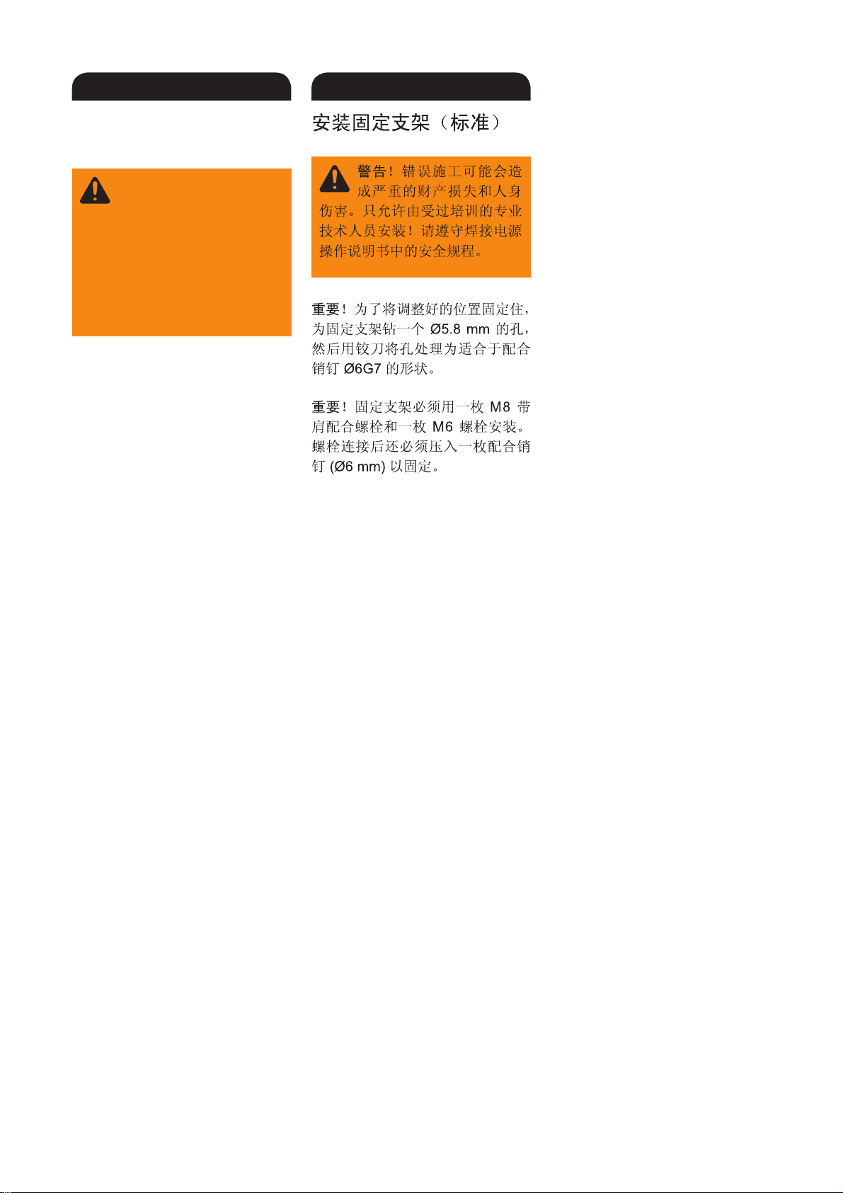
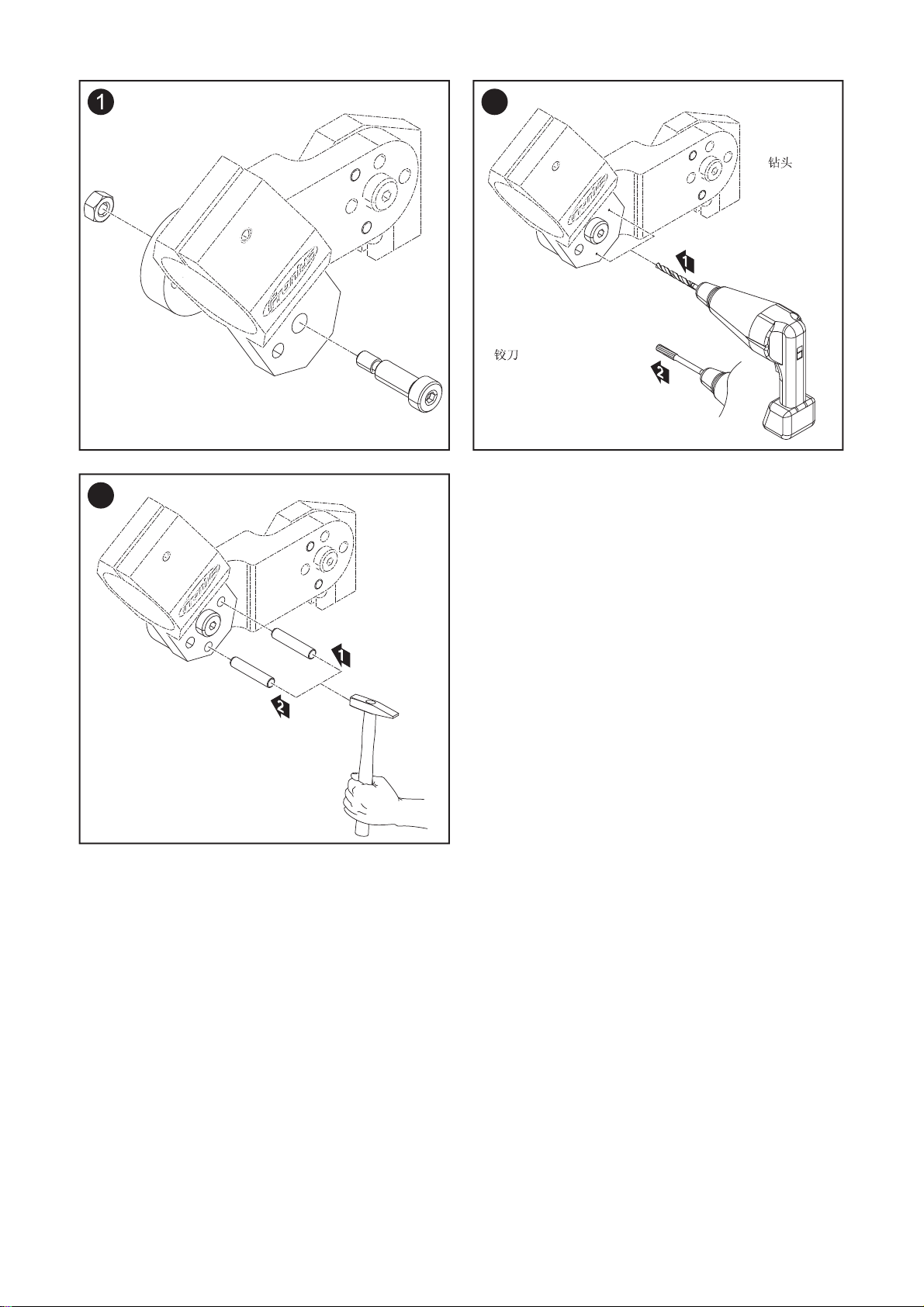
Fitting the mounting
bracket (standard)
WARNING! Work perfor-
med incorrectly can cause
serious injury to people and
damage to property. This installation must only be carried out
by trained and qualified personnel. Observe the safety rules in
the power source operating
instructions.
Important! Drill a Ø5.8 mm hole
for the mounting bracket and use a
reamer to enlarge the hole so it
can accommodate the dowel pin
(Ø6G7).
Important! The mounting bracket
must be fitted using an M8 shoulder screw and an M6 screw. After
screwing the mounting bracket in
place, another dowel pin (Ø6 mm)
must be driven in to secure it.
ZHEN
11
Page 14
2
Drill /
Ø5,8
Reamer /
Ø6G7
3
12
Page 15

Fitting the mounting
bracket (individually)
WARNING! Work perfor-
med incorrectly can cause
serious injury to people and
damage to property. This installation must only be carried out
by trained and qualified personnel. Observe the safety rules in
the power source operating
instructions.
Important! Drill a Ø5.8 mm hole
for the mounting bracket and use a
reamer to enlarge the hole so it
can accommodate the dowel pin
(Ø6G7).
Important! The mounting bracket
must be fitted using an M8 shoulder screw. The required bracket
must then be positioned and two
dowel pins (Ø6 mm) driven in to
secure it.
ZHEN
13
Page 16

1
1
1
2
1
4
3
2
4
3
1
2
4
3
2
5
14
Page 17

Robacta torch necks dismantling and assembling
NOTE! Risk of coolant
escaping through loose
union nut. When fitting the torch
neck, ensure that the union nut is
securely fastened: Tighten union
nut using a flat spanner.
For a defined, reproducible tightening torque, use a flat spanner and
torque wrench, ideal tightening
torque = 18 ±2 Nm.
ZHEN
15
Page 18

1
2
1
3
2
1
54
6
7
3
3
1
2
1
5
3
5
6
4
2
4
5
16
6
x.3
x.2
x.1
2
1
x.3
x.1
x.2
3
Page 19

Dismantling and assembling Robacta
Twin torch necks
NOTE! Risk of coolant
escaping through loose
union nuts. When fitting the Twin
torch neck, ensure that the union
nuts are securely fastened: Tighten
union nuts using flat spanner and
torque wrench, tightening torque =
18 ±2 Nm.
NOTE! When connecting
and terminating lines,
observe the following sequence:
1. Blow-out line x.1
2. Water flow x.2 (blue)
3. Water return x.3 (red)
ZHEN
17
Page 20

1
1
2
3
*
4
5
18
Page 21

Connecting the robot
hose pack
* Connection for torch blow-off
option
NOTE! Shielding gas
mixed with extraneous air
has an adverse effect on welding
results.
- The end of the hose must be
sealed off with the stopper
supplied if the torch blow-off
connection is not in use
- Do not connect the hose if no
compressed air is connected
to the solenoid valve for the
blow-off function. Seal hose
with stopper.
ZHEN
19
Page 22

20
Page 23

Correct laying of the
robot hose pack
To attain optimum wirefeed, observe the following when laying the
hose pack:
- Do not kink the hose pack
- Arrange the hose pack in as
straight a line as possible
- Do not overstretch the hose
pack, especially in robot mode
- Keep bends in the hose pack
as wide as possible
- Use balancers and hose pack
holders (e.g.: Universal hose
pack holder)
ZHEN
21
Page 24

1
2
1
2
3
1
4
2
*
1
*
1
22
Page 25

Replacing the gas nozz-
obacta 160/300/500
le
Robacta 700/700 Time
NOTE! The O-rings may
be damaged if the gas
nozzle is removed or
replaced incorrectly. Always open
the union nut before removing or
replacing the gas nozzle.
Important! When replacing the
gas nozzle, ensure that the holes
on the perforated ring are positioned exactly over the holes in the
torch body. Otherwise, sufficient
cooling of the gas nozzle cannot
be guaranteed.
* specified direction of rotation
ZHEN
23
Page 26

2
3
5
4
6
24
Page 27

Replacing welding
torch wearing parts Robacta
1. Robacta 160
2. Robacta 280
3. Robacta 300 / 500
4. Robacta 400
5. Robacta 700 / 700 TIME
6. Robacta 2500
ZHEN
25
Page 28

7
26
Page 29

Replacing welding
torch wearing parts Robacta
7. Robacta 5000
ZHEN
27
Page 30

1
1
2
2
4
3
2
1
3
1
2
8 Nm
4
*
3
4
1
28
Page 31

Replacing welding
torch wearing parts Robacta Twin
Important! Always use two identi-
cal contact tubes.
NOTE! Risk of serious
damage.
ALWAYS observe the work sequence and the specified torques.
* Instead of the standard tool
provided, a torque wrench and
appropriate box spanner are
also available. This ensures
that the components can be
tightened to the specified
torque.
For item numbers, see spare
parts list.
ZHEN
29
Page 32

1
mm
0,6 0,8 1,0 1,2 1,60,9
1,1 1,3* 1,6* 1,9* 2,31,6*
1,6 1,9 2,3 2,9*1,9
inch
.023 .030 .040 .045 1/16.035
.043 .051* .063* .075* .091.063*
.063 .075 .075 .091 .115*
30
Page 33

Standard values for
steel liners
Important! Inner liners are sup-
plied in overlengths.
Use bare steel liner
* recommended
ZHEN
31
Page 34

1
4
3
2
1
2
1
5
2
5
3
2
1
4
*
3
(.32 - .35 in.)
8 - 9 mm
2
3
**
m
(0 - .04 in.)
0 - 1 m
2
2
1
1
2
1
5
1
2
3
4
5
32
Page 35

Fitting the steel liner
Robacta 280 / 400 Robacta 2500 / 5000
Robacta Twin
Torch neck with nozzle fitting
screwed on
NOTE! When cutting the
liner to length, make sure
that
- no flash protrudes into the liner
- Place the cutting pliers at a
slight angle (flash is pulled
outwards)
- File down any flash
* Contact tube with centre hole
** Contact tube without centre
hole
ZHEN
33
Page 36

1
2
1
2
1
33
(0 in.)
0 mm
3
2
3
2
3
3
4
2
(.32 in.)
8 mm
*
2
1
2
1
(.63 in.)
16 mm
2
1
4
3
1
**
4
3
5
1
2
3
2
3
6
(- .32 in.)
- 8 mm
*
(- .63 in.)
- 16 mm
1
2
5
**
34
Page 37

Fitting the steel liner
Robacta 160/300/500
Robacta 700/700 Time
Torch neck with no nozzle fitting
screwed on
NOTE! When cutting the
liner to length, make sure
that
- no flash protrudes into the liner
- Place the cutting pliers at a
slight angle (flash is pulled
outwards)
- File down any flash
* Contact tube with centre hole
** Contact tube without centre
hole
ZHEN
35
Page 38

1
mm
2
mm
0,8
0,6
1,1 1,1 1,5 2,0 2,5
1,0 1,2 1,60,9
1,5
inch
.023 .030 .040 .045 1/16.035
.059 .079 .098
.059.043.043
0,8
0,6
1,5
1,5
1,5
inch
.023 .030 .040 .045 1/16.035
.059.059.059
1,0 1,2 1,60,9
1,5 2,0 2,5
.059 .079 .098
36
Page 39

Standard values for
graphite combination
liners and Teflon liners
NOTE! For aluminium
applications, choose the
next largest contact tube diameter.
Important! Inner liners are supplied in overlengths.
Figure 1: Graphite combination
liners
Figure 2: Teflon liners
ZHEN
37
Page 40

3
1
2
(.04 - .08 in.)
1 - 2 mm
3
5
6
1
1
38
1
Page 41

Fitting plastic liners
(Fronius connection
with no wirefeeding
nozzle)
applies to:
Teflon liners
Combination liners
Graphite liners
NOTE! Feed the inner liner
as close to the feed rollers
as possible, but do not let them
touch.
NOTE! Before feeding in
the filler wire, round off the
end of the wire.
ZHEN
39
Page 42

4
1
5
2
1
40
Page 43

Fitting plastic liners
(Fronius connection
with wirefeeding nozzle)
applies to:
Teflon liners
Combination liners
Graphite liners
* Plastic component - do not
overtighten!
NOTE! Guide the wirefee-
ding nozzle as close to
the feed rollers as possible, but do
not let them touch.
NOTE! Before feeding in
the filler wire, round off the
end of the wire.
ZHEN
41
Page 44

3
1
4
2
*
2
(.04 - .08 in.)
1-2 mm
3
2
5
1
3
2
4
5
6
1
1
1
42
Page 45

Fitting plastic liner
(Euro connection)
applies to:
Teflon liners
Combination liners
Graphite liners
* Inlet nozzle option
(42,0001,5621)
NOTE! Feed the inner liner
or inlet nozzle as close to
the feed rollers as possible, but do
not let them touch.
NOTE! Before feeding in
the filler wire, round off the
end of the wire.
ZHEN
43
Page 46

44
Page 47

Care, maintenance
and disposal
Regular preventive maintenance of
the welding torch is essential for
problem-free operation. The welding
torch is subjected to high temperatures and heavy soiling. The
welding torch therefore requires
more frequent maintenance than
other components in the welding
system.
Important! When removing welding spatter, avoid scoring or
scratching the torch. Future
welding spatter may become firmly
lodged in score or scratch marks.
- Do NOT bend the torch neck
ZHEN
45
Page 48

Robacta 700
2
1
2
1
*
*
*
46
Page 49

Care, maintenance
and disposal
Every start-up:
- Check the contact tube
- Replace worn out contact tube
- Remove welding spatter from
gas nozzle (e.g. manually, by
blowing off, or by using a
Robacta Reamer or Robacta
TC 1000)
- If there is dirt that cannot be
removed from around the
nozzle join, replace the gas
nozzle
* Check spatter guard or insula-
tion for damage
Water-cooled welding torch:
- Check the water connections
for leaks
-
Monitor the water return level in
the coolant container and vent
the cooling unit if necessary
ZHEN
47
Page 50

1
2
48
Page 51

Care, maintenance
and disposal
Every time the wirespool is changed:
- Recommended: replace inner
liner
- Clean wirefeeding hose with
reduced compressed air
- Clean wearing parts before
fitting
Disposal:
- Dispose of in accordance with
the applicable national and
local regulations.
ZHEN
49
Page 52

1
2
3
4
50
Page 53

Recognising faulty
wearing parts
1. Insulating parts
- Notches
- Burned off or torn middle
bar
- Scorched or torn-off shoulders
2. Nozzle fittings
- Notches and burns on the
front edge
- heavily covered in welding
spatter
3. Spatter guard
- Burned-off outside edges
- Notches
4. Contact tubes
- Worn out (oval) wire entry
and wire exit holes
- Heavily covered in welding
spatter
- Burns on the tip of the
contact tube
ZHEN
51
Page 54

EN
Troubleshooting
No welding current
Mains switch is on, indicators on the power source are lit, shielding gas available
Cause: Incorrect earth (ground) connection
Remedy: Check the earth (ground) connection and clamp for correct polarity
Cause: There is a break in the current cable in the welding torch
Remedy: Replace the torch
No shielding gas
All other functions are OK
Cause: The gas cylinder is empty
Remedy: Change the gas cylinder
Cause: Gas pressure regulator is faulty
Remedy: Change the gas pressure regulator
Cause: The gas hose is not connected, or is damaged or kinked
Remedy: Connect/replace the gas hose, or straighten out kinks
Cause: The welding torch is defective
Remedy: Replace welding torch
Cause: Gas solenoid valve is defective
Remedy: Replace gas solenoid valve
Poor welding properties
Cause: Incorrect welding parameters
Remedy: Check the settings
Cause: Poor connection to earth (ground)
Remedy: Ensure good contact to workpiece
Cause: Not enough shielding gas, or none at all
Remedy: Check the pressure regulator, gas hose, gas solenoid valve and torch gas connection.
Cause: Welding torch is leaking
Remedy: Replace welding torch
Cause: Contact tube is too large or worn out
Remedy: Change the contact tube
Poor welding properties
Cause: Wrong wire alloy or wrong wire diameter
Remedy: Check the wirespool that has been inserted
Cause: Wrong wire alloy or wrong wire diameter
Remedy: Check weldability of the base material
Cause: The shielding gas is not suitable for this wire alloy
Remedy: Use the correct shielding gas
Cause: Unfavourable welding conditions: shielding gas is contaminated (by moisture, air), inadequate gas
shielding (weld pool „boiling“, draughts), contaminants in the workpiece (rust, paint, grease)
Remedy: Optimise the welding conditions
52
Page 55

Cause: Welding spatter in the gas nozzle
Remedy: Remove welding spatter
Poor welding properties
Cause: Turbulence caused by too high a rate of shielding gas flow
Remedy: Reduce amount of shielding gas,
recommended shielding gas quantity (l/min) = wire diameter (mm) x 10
(e.g. 16 l/min for 1.6 mm filler wire)
Cause: Too large a distance between the welding torch and the workpiece.
Remedy: Reduce the distance between the welding torch and the workpiece (recommended: 10-15 mm)
Cause: Tilt angle of the welding torch is too great
Remedy: Reduce the tilt angle of the welding torch
Cause: Wirefeed components have incorrect diameter
Remedy: Use wirefeed components with correct diameter
Poor wirefeed
Cause: The braking force has been set too high
Remedy: Reduce the braking force
Cause: Hole in the contact tube is displaced
Remedy: Change the contact tube
Cause: Faulty wire feed liner in torch
Remedy: Check the wire feed liner for kinks, dirt, etc.
Cause: The wirefeed rollers are not suitable for the filler wire being used
Remedy: Use suitable wirefeed rollers
Cause: Feed rollers have the wrong contact pressure
Remedy: Adjust the contact pressure
Cause: The wirefeed rollers are soiled or damaged
Remedy: Clean the wirefeed rollers or exchange them for new ones
Cause: Inner liner wrongly laid or kinked
Remedy: Replace inner liner
Cause: Inner liner or wire inlet nozzle wrongly dimensioned
Remedy: Ensure inner liner or wire inlet nozzle are correctly dimensioned
Cause: Inner liner was kinked while being inserted
Remedy: When inserting the inner liner, only handle it around the infeed tube
Cause: AlSi filler wire: Filler wire damaged by the bronze insert
Remedy: Teflon liner must reach the contact tube
Cause: The inner liner has been cut too short
Remedy: Replace the inner liner and cut it to the correct length
Cause: Welding wire worn due to overly heavy contact pressure at the feed rollers
Remedy: Reduce contact pressure at the feed rollers
Cause: Filler wire contains impurities / corroded
Remedy: Use high-quality filler wire with no impurities
53
Page 56

The welding torch becomes very hot
Cause: Loose union nut on central connector
Remedy: Tighten the union nut
Cause: The welding torch has been operated beyond its maximum number of amps.
Remedy: Reduce welding power or use a higher capacity torch
Cause: The design dimensions of the torch are not sufficient for this task
Remedy: Observe the duty cycle and loading limits
Cause: Only on water-cooled machines: Water flow rate is insufficient
Remedy: Check water level, water flow rate and cleanliness, and arrangement of hose pack, etc.
Contact tube only has a short service life
Cause: Wrong feed rollers
Remedy: Use correct feed rollers
Cause: Welding wire worn due to overly heavy contact pressure at the feed rollers
Remedy: Reduce contact pressure at the feed rollers
Cause: Filler wire contains impurities / corroded
Remedy: Use high-quality filler wire with no impurities
Cause: Uncoated filler wire
Remedy: Use filler wire with suitable coating
Cause: Wrong dimension of contact tube
Remedy: Use a contact tube of the correct dimension
Cause: Duty cycle of welding torch has been exceeded
Remedy: Shorten the ON times or use a higher capacity torch
Cause: Contact tube has overheated. No thermal dissipation, as the contact tube is loose
Remedy: Tighten the contact tube
NOTE! When using CrNi, the contact tube may be subject to a higher degree of wear due to the nature
of the surface of CrNi welding wire.
Feeder inching button malfunction
Cause: Plug-in connections of „feeder inching button/control line/power source“ faulty
Remedy: Check plug-in connection / have power source or welding torch serviced
Cause: Control line is faulty
Remedy: Replace control line / have welding torch repaired
54
Page 57

Weld seam porosity
Cause: Spattering in the gas nozzle, causing inadequate gas-shielding of the weld seam
Remedy: Remove welding spatter
Cause: Either the shielding gas hose has holes in it, or the hose is not connected properly
Remedy: Replace shielding gas hose
Cause: The O-ring seals on the connection points have been cut through or are faulty
Remedy: Change the O-ring seals
Cause: Moisture/condensation in the shielding gas line
Remedy: Dry shielding gas line
Cause: Shielding gas flow is either too high or too low
Remedy: Correct the shielding gas flow
Cause: Insufficient shielding gas flow when welding starts or finishes
Remedy: Increase gas pre-flow or gas post-flow
Cause: Rusty or poor quality filler wire
Remedy: Use high-quality filler wire with no impurities
Cause: Too much parting agent applied
Remedy: Remove superfluous parting agent / apply less parting agent
55
Page 58

ZH
ZH
56
Page 59

57
Page 60

Page 61

Page 62

Technical Data
Torch necks
Explanation of symbols:
Water-cooled torch neck
X .......... Duty cycle in %
ED* ...... Duty cycle
I
........ max. welding current in A
max
(M6) ....... with contact tube M6
(M8) ....... with contact tube M8
Electrode diameter
Ø
Voltage measurement (V-Peak): for mechanically driven welding
torches: 141 V
ZHEN
ED*
Ø
This product conforms to the
requirements of IEC 60974-7.
ud_fr_st_mb_01620 01/2016
I
Page 63

Robacta 160 Robacta 280 Robacta 300 Robacta 400
Ø
Ø
Ø
Ø
Ø
X / I
(10 min / 40°C) [%] / [A] - - - -
max
M21 (EN 439) [%] / [A] - - - [%] / [A] 100 / 160 100 / 280 100 / 350 100 / 250 (M6); 400 (M8)
(10 min / 40°C) [%] / [A] - - - -
X / I
max
C1 (EN 439) [%] / [A] - - - [%] / [A] 100 / 160 100 / 280 100 / 350 100 / 250 (M6); 400 (M8)
[mm] 0,8-1,2 0,8-1,2 0,8-1,2 0,8-1,2
[in.] .031-.047 .031-.047 .031-.047 .031-.047
Robacta 500 Robacta 700 Robacta 700 Robacta 2500
TIME
X / I
(10 min / 40°C) [%] / [A] - - - -
max
M21 (EN 439) [%] / [A] - - - [%] / [A] 100 / 500 100 / 700 100 / 700 100 / 250
X / I
(10 min / 40°C) [%] / [A] - - - -
max
C1 (EN 439) [%] / [A] - - - [%] / [A] 100 / 500 100 / 700 100 / 700 100 / 250
[mm] 0,8-1,6 1,0-1,6 1,0-1,6 0,8-1,2
[in.] .031-.063 .039-.063 .039-.063 .031-.047
Robacta 5000 Robacta 7000 MTW 500-M (Con-Drive) Laser HD/W
X / I
(10 min / 40°C) [%] / [A] - - - -
max
M21 (EN 439) [%] / [A] - - - [%] / [A] 100 / 500 100 / 700 100 / 500 100 / 250
X / I
(10 min / 40°C) [%] / [A] - - - -
max
C1 (EN 439) [%] / [A] - - - [%] / [A] 100 / 500 100 / 700 100 / 500 100 / 250
[mm] 0,8-1,6 1,0-1,6 0,8-1,6 1,0-1,6
[in.] .031-.063 .039-.063 .031-.063 .039-.063
Robacta Twin Robacta Twin Robacta Twin Robacta Twin
Single 300 500 600 900
X / I
(10 min / 40°C) [%] / [A] - - - -
max
M21 (EN 439) [%] / [A] - - - [%] / [A] 100 / 300 100 / 500 (2 x 250) 100 / 600 (2x300) 100 / 900 (2x450)
[mm] 0,8-1,2 0,8-1,6 0,8-1,2 1,0-1,6
[in.] .031-.047 .031-.063 .031-.047 .039-.063
Robacta Twin Robacta Twin
900 Compact Compact PRO
X / I
(10 min / 40°C) [%] / [A] - -
max
M21 (EN 439) [%] / [A] - [%] / [A] 100 / 900 (2 x 450) 100 / 900 (2 x 450)
[mm] 1,0-1,6 1,0-1,6
[in.] .039-.063 .039-.063
ud_fr_st_mb_01462 01/2019
II
Page 64

MTB 500i W/R MTB 330i W/R
Ø
Ø
Ø
X / I
(10 min / 40°C) [%] / [A] - -
max
M21 (EN 439) [%] / [A] - [%] / [A] 100 / ED* 500 100 / ED* 330
(10 min / 40°C) [%] / [A] - -
X / I
max
C1 (EN 439) [%] / [A] - [%] / [A] 100 / ED* 500 100 / ED* 330
[mm] 1,0-1,6 0,8-1,6
[in.] .039-.063 .032-.063
MTB 500d W/R MTB 350d W/R MTB 330d W/R
X / I
(10 min / 40°C) [%] / [A] - -
max
M21 (EN 439) [%] / [A] - [%] / [A] 100 / ED* 500 100 /ED* 350 100 / ED* 330
X / I
(10 min / 40°C) [%] / [A] - -
max
C1 (EN 439) [%] / [A] - [%] / [A] 100 / ED* 500 100 / ED* 350 100 / ED* 330
[mm] 1,0-1,6 0,8-1,6 0,8-1,6
[in.] .039-.063 .032-.063 .032-.063
MTB 400d G/R MTB 350d G/R MTB 330d G/R
X / I
(10 min / 40°C) [%] / [A] 40 / ED* 400 40 / ED* 350 40 / ED* 330
max
M21 (EN 439) [%] / [A] 60 / ED* 320 60 / ED* 300 60 / ED* 270
[%] / [A] 100 / ED* 260 100 / ED* 250 100 / ED* 220
X / I
(10 min / 40°C) [%] / [A] - - -
max
C1 (EN 439) [%] / [A] 60 / ED* 400 60 / ED* 350 60 / ED* 330
[%] / [A] 100 / ED* 320 100 / ED* 300 100 / ED* 270
.
[mm] 0,8-1,6 0,8-1,6 0,8-1,6
[in.] .032-.063 .032-.063 .032-.063
III
ud_fr_st_mb_01462 01/2019
Page 65

Technical Data
Hosepacks
Explanation of symbols:
Water cooling
Length of the hosepack
X ............ Duty cycle in %
I
..........
max
* Lowest cooling power as per
Voltage measurement (V-Peak):
- for mechanically driven welding
max. welding current in A
Electrode diameter
Ø
IEC 60974-2, depends on the
length of the hosepack
torches: 141 V
ZHEN
Ø
This product conforms to the
requirements of IEC 60974-7.
I
ud_fr_st_mb_01621 01/2016
Page 66

Robacta Robacta W/CB-PAP
X / I
(10 min / 40°C) [%] / [A] - -
max
M21 (EN 439) [%] / [A] - -
[%] / [A] 100 / 700 100 / 500
X / I
(10 min / 40°C) [%] / [A] - -
max
C1 (EN 439) [%] / [A] - -
[%] / [A] 100 / 700 100 / 500
[mm] 0,8-1,6 0,8-1,6
Ø
[in.] .031-.063 .031-.063
[m] ([W]) 1,2 (1100) / 1,5 (1300) / 1,19 (550) / 1,30 (550) / 1,33 (550) / 1,38 (550) /
[m] ([W]) 1,75 (1400) / 2,5 (1400) / 1,39 (600) / 1,41 (600) / 1,46 (600) / 1,48 (600) /
P
min
*
[m] ([W]) 3,5 (1700) / 4,5 (2100) 1,51 (600) / 1,59 (650) / 1,60 (650) / 1,65 (650) /
[m] ([W]) 1,67 (650) / 1,68 (650) / 1,72 (650) / 1,80 (700)
[ft.] ([W]) 3.9 (1100) / 4.9 (1300) / 3.9 (550) / 4.2 (550) / 4.3 (550) / 4.5 (550) /
[ft.] ([W]) 5.7 (1400) / 8.2 (1400) / 4.5 (600) / 4.6 (600) / 4.7 (600) / 4.8 (600) /
[ft.] ([W]) 11.4 (1700) / 14.7 (2100) 4.9 (600) / 5.2 (650) / 5.2 (650) / 5.4 (650) /
[ft.] ([W]) 5.4 (650) / 5.5 (650) / 5.6 (650) / 5.9 (700)
Q
min
[L/min] 1 1
[gal./min] .26 .26
p
min
[bar] 3 3
[psi.] 43 43
p
max
bar 5,5 5,5
psi. 79.74 79.74
Robacta Twin Robacta Twin Robacta Twin
4,25m Compact / Complete
X / I
(10 min / 40°C) [%] / [A] - - -
max
M21 (EN 439) [%] / [A] - - -
[%] / [A] 100 / 900 (2 x 450) 100 / 720 (2 x 360) 100 / 900 (2 x 450)
[mm] 0,8-1,2 0,8-1,2 0,8-1,6
Ø
[in.] .031-.047 .031-.047 .031-.063
[m] ([W]) 1,6 (1400) / 2,6 (1900) 4,5 (2000) 1,6 (1400) / 2,6 (1900)
[m] ([W]) 3,6 (2400)
P
min
*
[ft.] ([W]) 5.25 (1400) / 8.53 (1900)14,76 (2000) 5.25 (1400) / 8.53 (1900)
[ft.] ([W]) 11.81 (2400)
Q
min
[L/min] 1 1 1
[gal./min] .26 .26 .26
p
min
[bar] 3 3 3
[psi.] 43 43 43
p
max
bar 5,5 5,5 5,5
psi. 79.74 79.74 79.74
ud_fr_st_mb_01621 01/2016
II
Page 67

Page 68

FRONIUS INTERNATIONAL GMBH
Froniusstraße 1, A-4643 Pettenbach, Austria
E-Mail: sales@fronius.com
www.fronius.com
Under www.fronius.com/contact you will find the addresses
of all Fronius Sales & Service Partners and locations
Find your
spareparts
online
 Loading...