

Page 1

/ Battery Charging Systems / Welding Technology / Solar Electronics
Motorversorgung 55 V / 4 A
Motor supply 55 V / 4 A
Alimentation moteur 55 V / 4 A
Einbauanleitung
WIG-Systemerweiterung
DEENFR
Installation instructions
TIG system add-on
Mode d’emploi
Extensions système TIG
42,0410,1287 002-28032012
Page 2

Page 3
Einbauanleitung KD-Motorversorgung 55 V / 4 A
WARNUNG! Fehlerhaft durchgeführte Arbeiten können schwerwiegende
Sach- und Personenschäden verursachen. Nachfolgend beschriebene Tätigkeiten dürfen nur von geschultem Fachpersonal durchgeführt werden! Beachten Sie die Sicherheitsvorschriften in der Bedienungsanleitung der Stromquelle.
WARNUNG! Ein Elektroschock kann tödlich sein. Vor Öffnen des Gerätes:
- Netzschalter der Stromquelle in Stellung - O - schalten
- Stromquelle vom Netz trennen
- Deutlich lesbares und verständliches Warnschild gegen Wiedereinschalten anbringen
Nach dem Öffnen des Gerätes gegebenenfalls spannungsführende Bauteile
(z.B. Kondensatoren) entladen.
Allgemeines
HINWEIS! Beachten Sie beim Umgang mit elektronischen Bauteilen und Prints
die ESD-Bestimmungen. Dazu gehören vor allem ESD-gerechte
- Verpackungen
- Arbeitsflächen
- Böden
- Sitzgelegenheiten
- Erdungsmöglichkeiten
DE
Für einen unsachgemäß behandelten elektronischen Bauteil oder Print können keine
Garantie- und Gewährleistungsansprüche geltend gemacht werden.
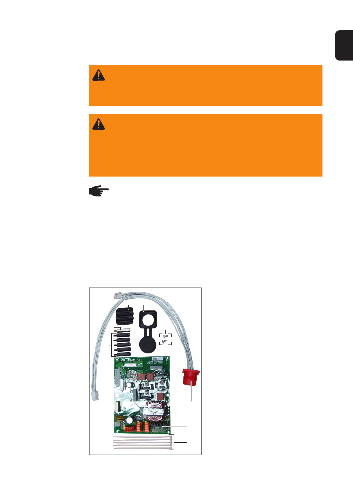
Bauteile Das Einbauset KD-Motorversorgung 55V/
4A (4,100,475) besteht aus folgenden
Bauteilen:
(1) Anschlussbuchse LocalNet
(2) Print NT 60
(3) 5 Kabelbinder
(4) 5 Distanzen Kunststoff
(5) 1 Distanz Messing
(6) Blindabdeckung
(7) Abdeckkappe
(8) 2 Schrauben
(4)
(5)
(6) (7)
(8)
(1)
(2)
Abb.1 Lieferumfang
(3)
1
Page 4
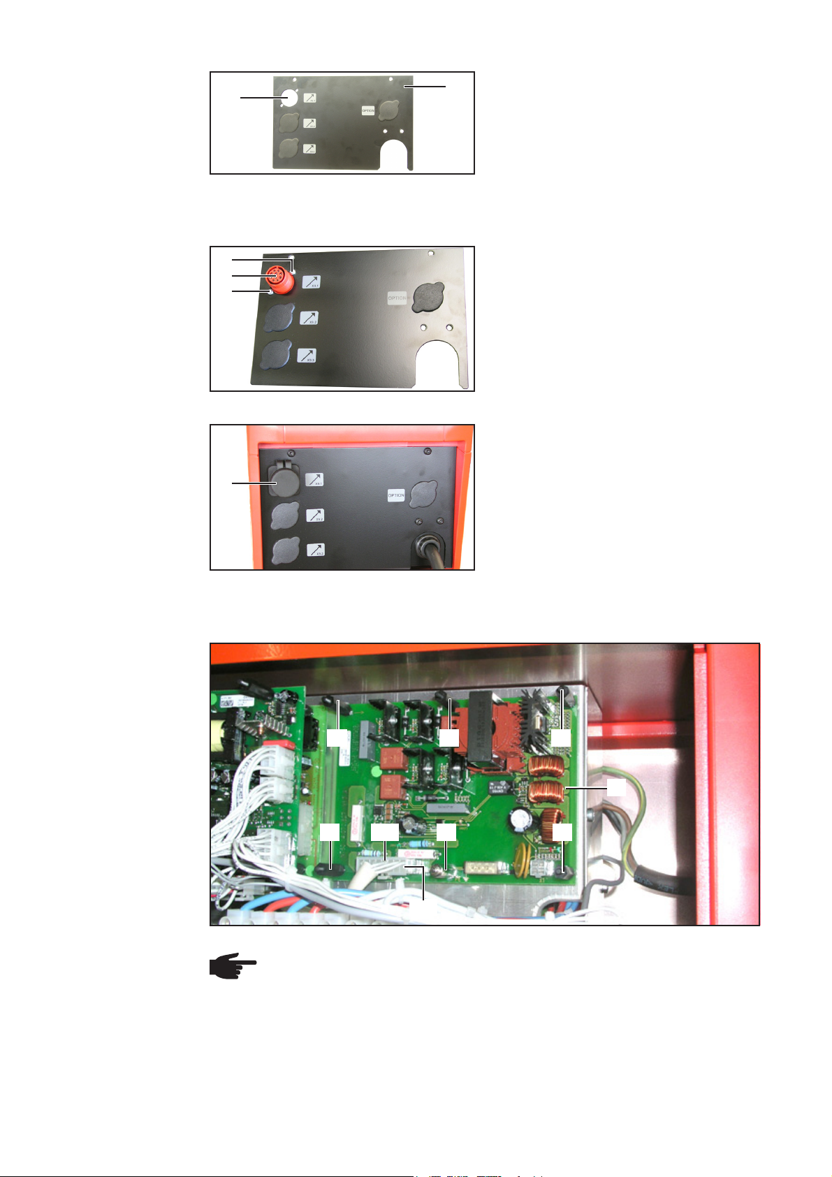
Rückfront demontieren
(10)
Abb.2 Blindabdeckung entfernen
(9)
1. Rechtes Seitenteil abmontieren
2. Rückfront (9) abmontieren
3. Blindabdeckung an der Durchführung
(10) entfernen
Beiliegende
Anschlussbuchse montieren
Print NT60 montieren
(8)
(1)
(8)
Abb.3 Anschlussbuchse montieren
(7)
Abb.4 Rückfront montieren
1. Beiliegende Anschlussbuchse (1)
mittels zwei Schrauben (8) an der
Rückfront montieren
2. Rückfront montieren
3. Beiliegende Abdeckkappe (7) aufsetzen
(4) (4) (4)
(2)
(11)
(5)
(4)(4)
X2
Abb.5 Print NT 60 montieren
HINWEIS! Auf korrekte Position der Distanz Messing (5) achten.
1. Print NT 60 (2) mittels 5 Distanzen Kunststoff (4) und einer Distanz Messing (5)
montieren
3. Vom 16-poligen Molexstecker (11) den Blindstecker (nicht abgebildet) abstecken
4. 16-poligen Molexstecker (11) am Print NT 60:X2 anstecken
2
Page 5
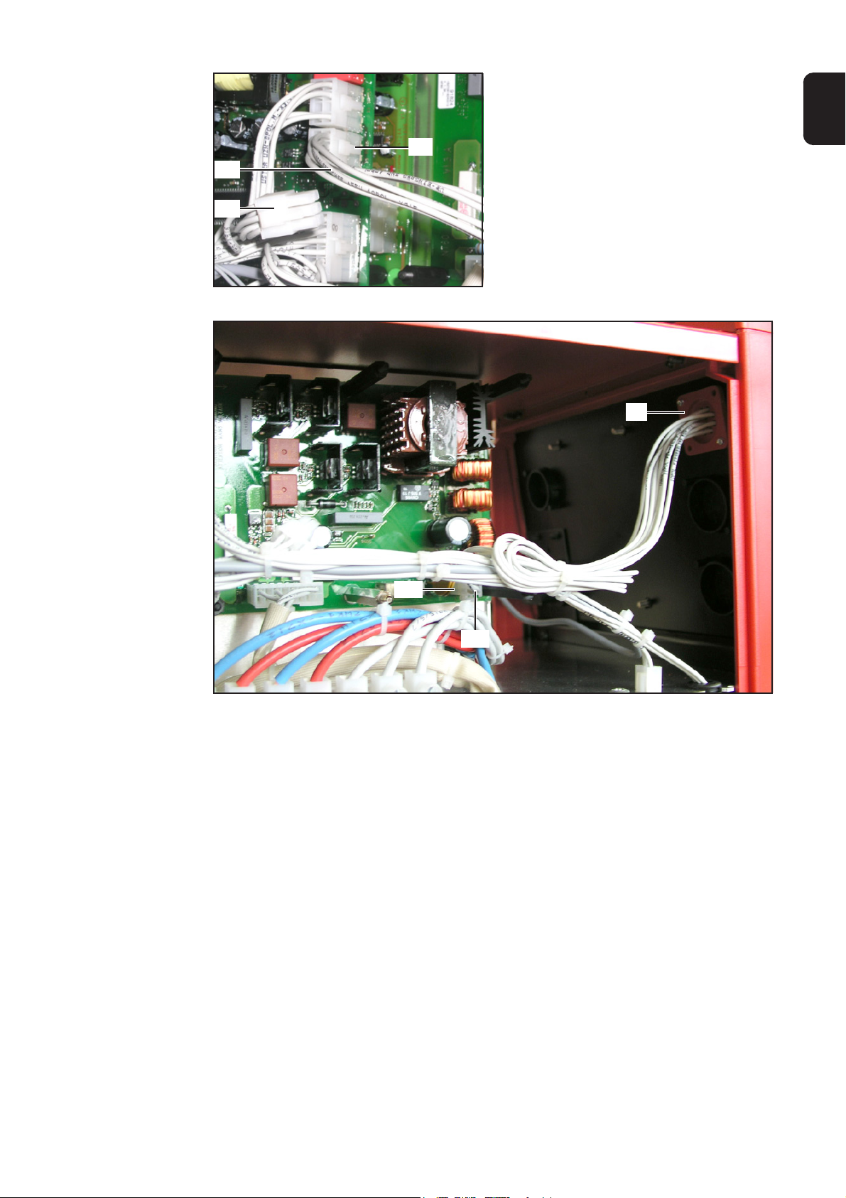
Print UST anschließen
Print NT60 anschließen
(13)
(12)
Abb.6 Print UST anschließen
X9
1. 6-poligen Molexstecker (12) vom Print
UST:X9 abstecken
2. Kabelbaum 6-polig (13) der beiliegenden Anschlussbuchse LocalNet (1) am
Print UST:X9 anstecken
(1)
DE
X1
(14)
Abb.7 Print UST anschließen
1. Kabelbaum 4-polig (14) der beiliegenden Anschlussbuchse LocalNet (1) am Print NT
60:X1 anstecken
2. Kabel mittels beiliegenden Kabelbindern fixieren
3
Page 6

Bestehende
Anschlussbuchse demontieren
(15)
(18)
X4
Gehäuse schließen
(17)
Abb.8 Anschlussbuchse an der Vorderfront
demontieren
Abb.9 Molexstecker abstecken
(16)
HINWEIS! Vor dem Entfernen der bestehenden Anschlussbuchse (15), falls
erforderlich, die Kabelbinder am zugehörigen Kabelbaum durchtrennen.
1. 6-poligen Molexstecker (16) am Print FU50:X4 abstecken
2. An der bestehenden Anschlussbuchse LocalNet (15) Abdeckkappe (17) abnehmen
3. An der bestehenden Anschlussbuchse LocalNet (15) zwei Schrauben (18) lösen
4. Bestehende Anschlussbuchse (15) entfernen
1. Beiliegende Blindabdeckung (6)
(6)
einsetzen
2. Rechtes Seitenteil montieren
Abb.10 Blindabdeckung einsetzen
4
Page 7

Installation instructions for KD motor supply 55V/4A
WARNING! Operating the equipment incorrectly can cause serious injury and
damage. The following activities must only be carried out by trained and
qualified personnel! Take note of the safety rules in the power source operating instructions.
WARNING! An electric shock can be fatal. Before opening the machine:
- Switch the power source mains switch to the „O“ position
- Unplug power source from the mains
- Attach a clearly legible and easy-to-understand warning sign to prevent
anyone switching it on again
After opening the machine, discharge any electrically charged components
(e.g. capacitors).
General remarks
Note! Observe ESD guidelines when handling electronic components and
PCBs. This primarily applies to ESD compatible
- packaging
- work surfaces
- floors
- seating
- earthing facilities
EN
No guarantee or warranty claims can be made in respect of any improperly handled
electronic component or PCB.
Components The KD motor supply 55V/4A installation
set (4,100,475) consists of the following
components:
(1) LocalNet connection socket
(2) NT 60 PCB
(3) 5 cable ties
(4) 5 plastic spacers
(5) 1 brass spacer
(6) Blanking cover
(7) Cap
(8) 2 screws
(4)
(5)
(6) (7)
(8)
(1)
(2)
(3)
Fig. 1 Scope of supply
1
Page 8

Removing the
back panel
(10)
Fig. 2 Removing the blanking cover
(9)
1. Remove the right side panel
2. Remove the back panel (9)
3. Remove blanking cover from bushing
(10)
Fitting the supplied connection
socket
Fitting the NT60
PCB
(8)
(1)
(8)
Fig.3 Fitting the connection socket
(7)
Fig. 4 Fitting the back panel
1. Fit connection socket provided (1) to
the back panel using two screws (8)
2. Fit back panel
3. Put cap (7) in place
(4) (4) (4)
(2)
(11)
(5)
(4)(4)
X2
Fig. 5 Fitting the NT 60 PCB
Note! Ensure that the brass spacer (5) is positioned correctly.
1. Fit NT 60 PCB (2) using 5 plastic spacers (4) and one brass spacer (5)
3. Unplug dummy plug (not illustrated) from 16-pin Molex plug (11)
4. Plug 16-pin Molex plug (11) into NT 60 PCB (X2)
2
Page 9

Connecting the
UST PCB
(13)
X9
1. Unplug 6-pin Molex plug (12) from
UST PCB (X9)
2. Plug 6-pin cable harness (13) of the
enclosed LocalNet connection socket
(1) into UST PCB (X9)
Connecting the
NT60 PCB
(12)
EN
Fig. 6 Connecting the UST PCB
(1)
X1
(14)
Fig. 7 Connecting the UST PCB
1. Plug 4-pin cable harness (14) of the enclosed LocalNet connection socket (1) into
NT 60 PCB (X1)
2. Bind cables together with cable ties supplied
3
Page 10

Removing the
existing connection socket
(15)
(18)
X4
Closing the
housing
(17)
Fig. 8 Removing the front panel connection socket
Fig. 9 Disconnecting the Molex plug
(16)
Note! Before removing the existing connection socket (15), cut through the the
cable ties on the accompanying cable harness if necessary.
1. Disconnect 6-pin Molex plug (16) from FU50 PCB (X4)
2. Remove cap (17) from existing LocalNet connection socket (15)
3. Undo two screws (18) on the existing LocalNet connection socket (15)
4. Remove the existing connection socket (15)
1. Insert the supplied blanking cover (6)
(6)
2. Fit the right side panel
Fig. 10 Inserting the blanking cover
4
Page 11

Mode d’emploi Alimentation moteur KD 55V/4A
AVERTISSEMENT ! Les erreurs en cours d’opération peuvent entraîner des
dommages corporels et matériels graves. Les opérations décrites ci-après
doivent être effectuées exclusivement par le personnel qualifié et formé !
Respectez les consignes de sécurité figurant dans le mode d’emploi de la
source de courant.
AVERTISSEMENT ! Un choc électrique peut être mortel. Avant d’ouvrir
l’appareil :
- Commuter l’interrupteur du secteur de la source de courant sur - O -
- Débrancher la prise secteur de la source de courant
- Placer un écriteau parfaitement lisible et compréhensible sur l’appareil
pour que personne ne le rallume
Après ouverture de l’appareil, le cas échéant, décharger les éléments conducteurs de tension (par ex. condensateurs).
Généralités
REMARQUE : Respectez les réglementations relatives aux décharges électro-
statiques lors de la manipulation des pièces électroniques et des circuits imprimés. Ces réglementations concernent principalement les éléments suivants
adaptés aux décharges électrostatiques :
- Emballages
- Plans de travail
- Sols
- Sièges
- Possibilités de mise à la terre
FR
La garantie ne couvre pas les pièces électroniques ou les circuits imprimés manipulés
de manière non conforme aux instructions.
Pièces Le kit d’installation Alimentation moteur KD
(6) (7)
(5)
(4)
Fig. 1 Livraison
(8)
(1)
(2)
(3)
1
55V/4A (4,100,475) se compose des
pièces suivantes :
(1) Connecteur LocalNet
(2) Circuit imprimé NT 60
(3) 5 attache-câbles
(4) 5 écarteurs en plastique
(5) 1 écarteur en laiton
(6) Fausse prise
(7) Capuchon protecteur
(8) 2 vis
Page 12

Démonter la
plaque arrière
(10)
Fig. 2 Enlever la fausse prise
(9)
1. Démonter la partie latérale droite
2. Démonter la plaque arrière (9)
3. Enlever la fausse prise du passage
(10)
Installer le connecteur fourni
Installer le circuit
imprimé NT60
(8)
(1)
(8)
Fig. 3 Installer le connecteur
(7)
Fig. 4 Monter la plaque arrière
1. Installer le connecteur fourni (1) au
moyen des deux vis (8) sur la plaque
arrière
2. Monter la plaque arrière
3. Mettre en place le capuchon protecteur fourni (7)
(4) (4) (4)
(2)
(11)
(5)
(4)(4)
X2
Fig. 5 Installer le circuit imprimé NT 60
REMARQUE : Veiller à positionner correctement l’écarteur en laiton (5).
1. Installer le circuit imprimé NT 60 (2) au moyen des 5 écarteurs en plastique (4) et de
l’écarteur en laiton (5)
3. Retirer la fausse prise (non illustrée) de la la fiche Molex 16 pôles (11)
4. Brancher la fiche Molex 16 pôles (11) sur le circuit imprimé NT 60:X2
2
Page 13

Raccorder le
circuit imprimé
UST
Raccorder le
circuit imprimé
NT60
(13)
(12)
Fig. 6 Raccorder le circuit imprimé UST
X9
1. Débrancher la fiche Molex 6 pôles (12)
du circuit imprimé UST:X9
2. Brancher le faisceau de câbles 6 pôles
(13) du connecteur LocalNet fourni (1)
sur le circuit imprimé UST:X9
FR
(1)
X1
(14)
Fig. 7 Raccorder le circuit imprimé UST
1. Brancher le faisceau de câbles 4 pôles (14) du connecteur LocalNet fourni (1) sur le
circuit imprimé NT 60:X1
2. Fixer les câbles au moyen des attache-câbles fournis
3
Page 14

Démonter le
connecteur
existant
(15)
(18)
X4
Fermer le boîtier
(17)
Fig. 8 Démonter le connecteur sur la plaque avant
Fig. 9 Débrancher la fiche Molex
(16)
REMARQUE : Avant d’enlever le connecteur existant (15), si nécessaire,
sectionner les attache-câbles au niveau du faisceau de câbles correspondant.
1. Débrancher la fiche Molex 6 pôles (16) sur le circuit imprimé FU50:X4
2. Retirer le capuchon protecteur (17) du connecteur LocalNet existant (15)
3. Desserrer les deux vis (18) du connecteur LocalNet existant (15)
4. Enlever le connecteur existant (15)
1. Mettre en place la fausse prise fournie
(6)
(6)
2. Monter la partie latérale droite
Fig. 10 Mettre en place la fausse prise
4
Page 15

FRONIUS INTERNATIONAL GMBH
Froniusplatz 1, A-4600 Wels, Austria
Tel: +43 (0)7242 241-0, Fax: +43 (0)7242 241-3940
E-Mail: sales@fronius.com
www.fronius.com
Under http://www.fronius.com/addresses you will find all addresses
www.fronius.com/addresses
of our Sales & service partners and Locations.
ud_fr_st_so_00082 012011
 Loading...