

Page 1

Adapter für Miller WIG-Schweißbrenner
Miller TIG torch adapter
Adaptateur pour torche de soudage
TIG Miller
Einbauanleitung
D
WIG-Systemerweiterung
Installation Instructions
GB
TIG system extension
Instructions d‘installation
F
Extension système TIG
42,0410,1412 012007
Page 2

Page 3

Sehr geehrter Leser
Einleitung
Wir danken Ihnen für Ihr entgegengebrachtes Vertrauen und gratulieren Ihnen zu Ihrem
technisch hochwertigen Fronius Produkt. Die vorliegende Anleitung hilft Ihnen, sich mit
diesem vertraut zu machen. Indem Sie die Anleitung sorgfältig lesen, lernen Sie die
vielfältigen Möglichkeiten Ihres Fronius-Produktes kennen. Nur so können Sie seine
Vorteile bestmöglich nutzen.
Bitte beachten Sie auch die Sicherheitsvorschriften und sorgen Sie so für mehr Sicherheit am Einsatzort des Produktes. Sorgfältiger Umgang mit Ihrem Produkt unterstützt
dessen langlebige Qualität und Zuverlässigkeit. Das sind wesentliche Voraussetzungen
für hervorragende Ergebnisse.
ud_fr_st_et_00491 012004
Page 4

Page 5

Allgemeines
Sicherheit
ESD-Bestimmungen
WARNUNG! Fehlerhaft durchgeführte Arbeiten können schwerwiegende Sach-
und Personenschäden verursachen. Nachfolgend beschriebene Tätigkeiten
dürfen nur von geschultem Fachpersonal durchgeführt werden! Beachten Sie
die Sicherheitsvorschriften in der Bedienungsanleitung der Stromquelle.
WARNUNG! Ein elektrischer Schlag kann tödlich sein. Vor Öffnen des Gerätes:
- Netzschalter der Stromquelle in Stellung - O - schalten
- Stromquelle vom Netz trennen
- Deutlich lesbares und verständliches Warnschild gegen Wiedereinschalten
anbringen
Nach dem Öffnen des Gerätes gegebenenfalls spannungsführende Bauteile
(z.B. Kondensatoren) entladen.
HINWEIS! Beachten Sie beim Umgang mit elektronischen Bauteilen und Prints
die ESD-Bestimmungen. Dazu gehören vor allem ESD-gerechte
- Verpackungen
- Arbeitsflächen
- Böden
- Sitzgelegenheiten
- Erdungsmöglichkeiten
Bauteile
Für einen unsachgemäß behandelten elektronischen Bauteil oder Print können keine
Garantie- und Gewährleistungsansprüche geltend gemacht werden.
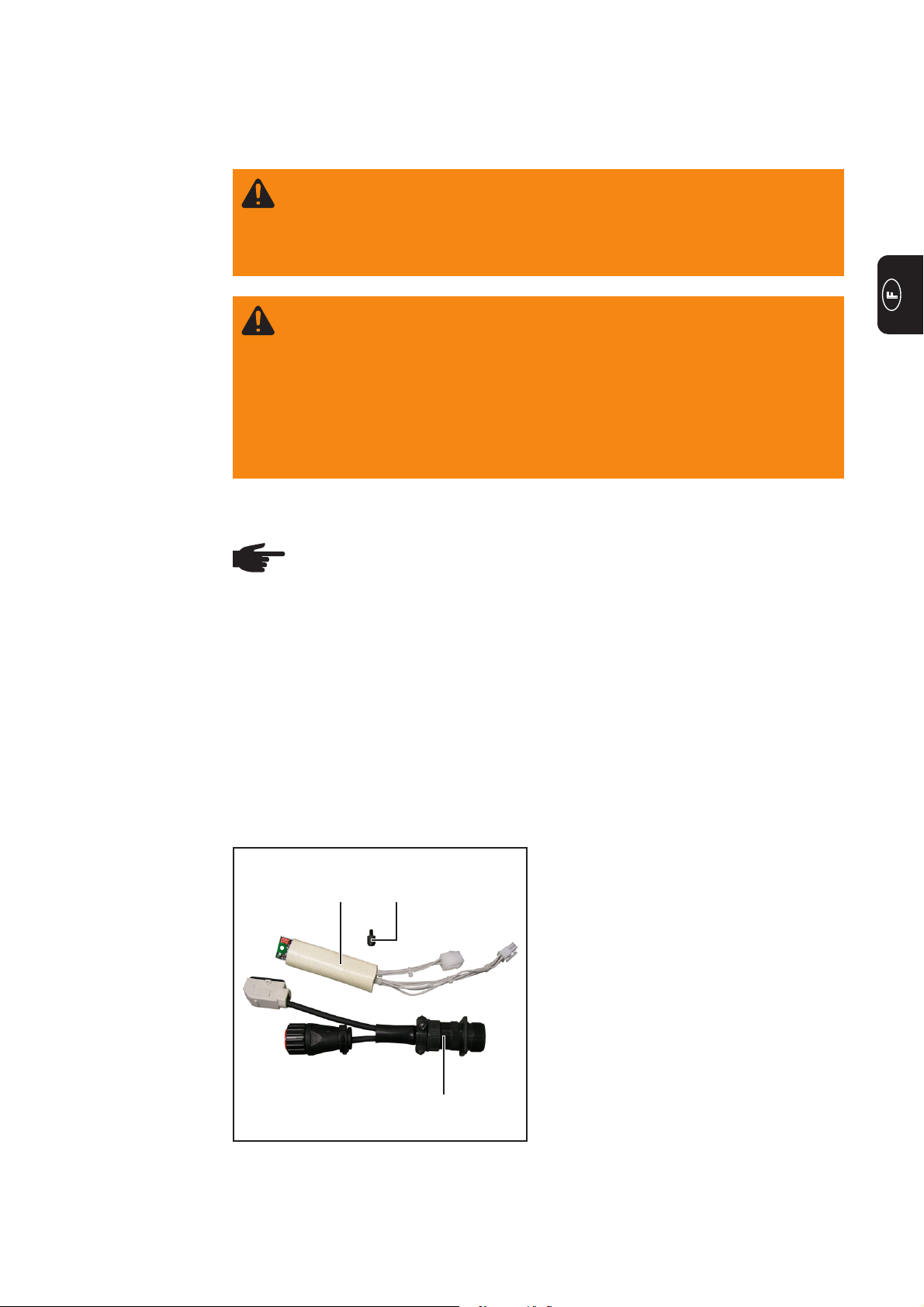
(1) Kabelbaum mit Print
(2) Kunststoff-Distanz M4 x 10 mm
(1)
Abb.1 Einbauset Adapter für Miller WIG-
Schweißbrenner
(2)
(3) Adapter für Miller WIG-Schweißbren-
ner
ohne Abbildung:
3 Stk. Kabelbinder
(3)
1
Page 6

Adapter für Miller WIG-Schweißbrenner einbauen
Allgemeines Der Einbau des Adapters für Miller WIG-Schweißbrenner wird anhand der Stromquelle
MagicWave 4000 beschrieben. Der Einbau in andere WIG-Stromquellen ist möglich und
erfolgt gemäß den folgenden Arbeitsschritten.
Vorbereitung 1. Netzschalter der Stromquelle in
Stellung - O - schalten
(1)
(1)
(1)
2. Stromquelle von Netz trennen
3. vorhandenen Schweißbrenner abmontieren
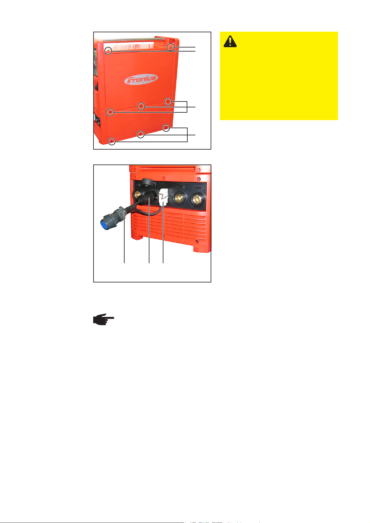
4. rechtes Seitenteil der Stromquelle
entfernen:
- Schrauben (1) entfernen
- Seitenteil abnehmen
Adapter für Miller
WIG-Schweißbrenner einbauen
Abb.2 Seitenteil entfernen
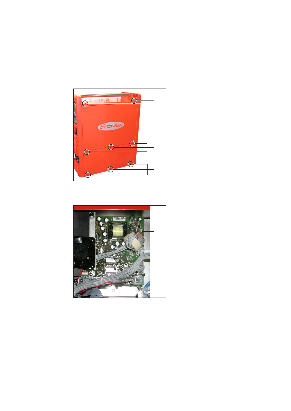
1. 6-poliger Molexstecker X9 (2) vom
Print UST 2C (1) abstecken
(1)
(2)
Abb.3 Stecker X9 abstecken
2
Page 7

Adapter für Miller
WIG-Schweißbrenner einbauen
(Fortsetzung)
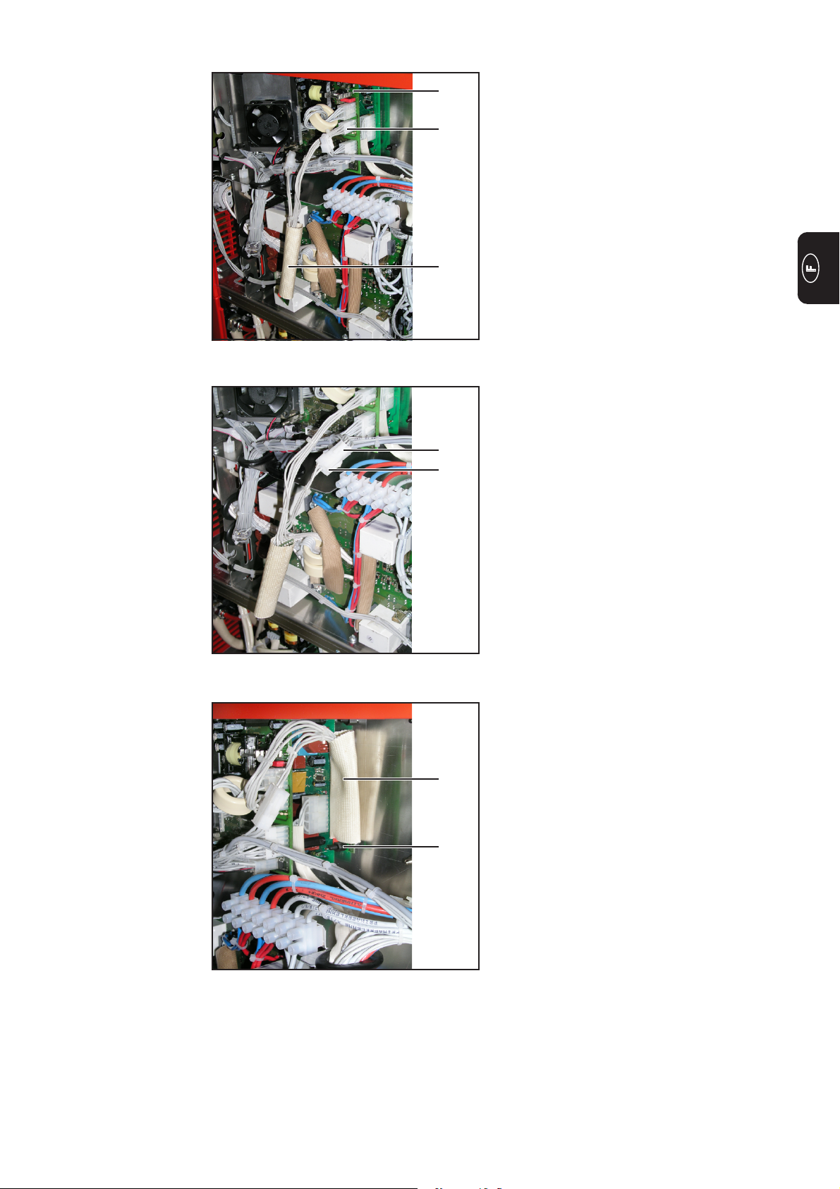
(1)
(3)
(4)
Abb.4 Kabelbaum am Print UST 2C anstecken
(2)
(5)
2. 6-poligen Molexstecker (3) vom
Kabelbaum mit Print (4) an X9 am
Print UST 2C (1) anstecken
3. 6-poligen Molexstecker (5) vom
Kabelbaum mit Print und den 6-poligen
Molexstecker der Stromquelle (2)
zusammenstecken
Abb.5 Kabelbaum mit der Stromquelle verbinden
(6)
(7)
Abb.6 Print vom Kabelbaum in der Stromquelle
befestigen
4. Print (6) vom Kabelbaum mit der
Bohrung über die vorhandene Kunststoff-Distanz stecken
5. Print (6) mit der Kunststoff-Distanz M4
x10 mm (7) fixieren
Nur wenn in der Stromquelle keine
entsprechende Kunststoff-Distanz
vorhanden ist:
- Isolierung über den Print schie-
ben, sodass der Print vollständig
von der Isolierung bedeckt ist
- Print mittels 3 Kabelbinder an
einem Kabelstrang befestigen
3
Page 8
Abschließende
Tätigkeiten
(1)
(1)
VORSICHT! Unzureichende
Schutzleiterverbindung kann
schwerwiegende Personen- und
Sachschäden verursachen. Die
Gehäuse-Schrauben stellen eine
geeignete Schutzleiterverbindung für die Erdung des Gehäuses dar und dürfen keinesfalls
durch andere Schrauben ohne
zuverlässige Schutzleiterverbindung ersetzt werden.
(1)
Abb.7 Seitenteil montieren
(2) (3) (4)
Abb.8 Adapter an der Stromquelle anschließen
1. rechtes Seitenteil der Stromquelle
montieren
2. Adapter (2) an der Stromquelle anschließen:
- den LocalNet-Stecker (3) am
Anschluss LocalNet
- den Tuchel-Stecker (4) am An-
schluss Brennersteuerung
Verwendung von
Fronius Standard-Systemkomponenten
HINWEIS! Nach dem Umbau der Stromquelle ist die Verwendung von Fronius
Standard-Systemkomponenten wie Schweißbrenner, Fernbedienungen, FußFernbedienungen, etc., nicht mehr möglich.
Um Fronius Standard-Systemkomponenten an der Stromquelle verwenden zu
können, muss die Stromquelle wieder zurückgebaut werden.
4
Page 9

Dear Reader
Introduction
Thank you for choosing Fronius - and congratulations on your new, technically highgrade Fronius product! This instruction manual will help you get to know your new
machine. Read the manual carefully and you will soon be familiar with all the many
great features of your new Fronius product. This really is the best way to get the most
out of all the advantages that your machine has to offer.
Please also take special note of the safety rules - and observe them! In this way, you
will help to ensure more safety at your product location. And of course, if you treat your
product carefully, this definitely helps to prolong its enduring quality and reliability - things
which are both essential prerequisites for getting outstanding results.
ud_fr_st_et_00493 012004
Page 10

Page 11

General remarks
Safety
ESD guidelines
WARNING! Work performed incorrectly can cause serious injury and damage.
The following activities must only be carried out by trained and qualified personnel! Observe the safety rules in the power source operating instructions.
WARNING! An electric shock can be fatal. Before opening the device:
- Turn the power source mains switch to the „O“ position
- Unplug the power source from the mains
- Attach a clearly legible and easy-to-understand warning sign to prevent
anyone switching it on again
After opening the device, discharge any electrically charged components (e.g.
capacitors).
NOTE: Observe ESD guidelines when handling electronic components and
PCBs. This primarily applies to ESD compatible
- packaging
- work surfaces
- floors
- seating
- earthing facilities
Components
No guarantee or warranty claims can be made in respect of any improperly handled
electronic component or PCB.
(1) Cable harness and PCB
(2) M4 x 10 mm plastic spacer
(1)
Fig. 1 Miller TIG torch adapter installation set
(2)
(3) Miller TIG torch adapter
Not illustrated:
3 x cable ties
(3)
1
Page 12
Installing the Miller TIG torch adapter
General remarks Installation of the Miller TIG torch adapter is described from the point of view of a Magic-
Wave 4000 power source It can be installed with other TIG power sources by following the
instructions below.
Preparations 1. Turn the power source mains switch to
the „O“ position
(1)
(1)
(1)
2. Unplug the power source from the
mains
3. Remove any existing torch
4. Remove the right side panel from the
power source:
- remove screws (1)
- take off side panel
Installing the
Miller TIG torch
adapter
Fig. 2 Removing the side panel
1. Disconnect the 6-pin X9 Molex plug (2)
from the UST 2C PCB (1)
(1)
(2)
Fig. 3 Disconnecting plug X9
2
Page 13

Installing the
Miller TIG torch
adapter
(continued)
(1)
(3)
(4)
Fig. 4 Plugging the cable harness into the UST
2C PCB
(2)
(5)
2. Plug the 6-pin Molex plug (3) from the
cable harness and PCB (4) into X9 on
the UST 2C board (1)
3. Plug the 6-pin Molex plug (5) from the
cable harness and PCB into the 6-pin
Molex plug on the power source (2)
Fig. 5 Connecting the cable harness to the power
source
(6)
(7)
Fig. 6 Securing the cable harness PCB in the
power source
4. Insert cable harness PCB (6) with the
hole over the existing plastic spacer
5. Fix PCB (6) with the M4 x10 mm
plastic spacer (7)
Only if there is no corresponding
plastic spacer in the power source:
- Push the insulation over the PCB
so that it totally covers the PCB
- Fasten the PCB to a wiring loom
using 3 cable ties
3
Page 14

Finally...
Fig. 7 Fitting the side panel
(1)
(1)
(1)
CAUTION! Inadequate PE
conductor connections can
cause serious injury and damage. The housing screws provide
a suitable PE conductor connection for earthing (grounding)
the housing and must NOT be
replaced by any other screws
which do not provide a reliable
PE conductor connection.
1. Fit the right side panel of the power
source
2. Connect the adapter (2) to the power
source:
- the LocalNet plug (3) to the
LocalNet interface
- the Tuchel plug (4) to the burner
control interface
Using Fronius
standard system
components
(2) (3) (4)
Fig. 8 Connecting the adapter to the power
source
NOTE: After converting the power source Fronius standard system components,
such as torches, remote control units, pedal remote control units, etc., can no
longer be used.
If you want to use Fronius standard system components with the power source,
the power source must be restored to its original configuration.
4
Page 15

Cher lecteur
Introduction
Nous vous remercions de votre confiance et vous félicitons d’avoir acheté un produit de
qualité supérieure de Fronius. Les instructions suivantes vous aideront à vous familiariser avec le produit. En lisant attentivement les instructions de service suivantes, vous
découvrirez les multiples possibilités de votre produit Fronius. C’est la seule manière
d’exploiter ses avantages de manière optimale.
Prière d’observer également les consignes de sécurité pour garantir une sécurité accrue
lors de l’utilisation du produit. Une utilisation soigneuse du produit contribue à sa longévité et sa fiabilité. Ce sont des conditions essentielles pour obtenir d’excellents résultats.
ud_fr_st_et_00500 012006
Page 16

Page 17
Généralités
Sécurité
Réglementations
relatives aux
décharges électrostatiques
AVERTISSEMENT ! Les erreurs en cours d’opération peuvent entraîner des
dommages corporels et matériels graves. Les opérations décrites ci-après
doivent être effectuées exclusivement par le personnel qualifié et formé !
Respectez les consignes de sécurité figurant dans le mode d’emploi de la
source de courant.
AVERTISSEMENT ! Une décharge électrique peut être mortelle. Avant d’ouvrir
l’appareil :
- Placer l’interrupteur secteur de la source de courant en position - O -
- Débrancher la prise secteur de la source de courant
- Placer un écriteau parfaitement lisible et compréhensible sur l’appareil
pour que personne ne le rallume
Après ouverture de l’appareil, le cas échéant, décharger les éléments conducteurs de tension (par ex. condensateurs).
REMARQUE ! Respectez les réglementations relatives aux décharges électrostatiques lors de la manipulation des composants électroniques et circuits
imprimés. Ces réglementations concernent principalement les éléments suivants
adaptés aux décharges électrostatiques :
- Emballages
- Plans de travail
- Sols
- Sièges
- Possibilités de mise à la terre
Éléments
La garantie ne couvre pas les composants électroniques et circuits imprimés manipulés
de manière non conforme aux instructions.
(1) Faisceau de câbles avec circuit
imprimé
(1)
Fig. 1 Kit d’installation de l’adaptateur pour
torche de soudage TIG Miller
(2)
(2) Écarteur en plastique M4 x 10 mm
(3) Adaptateur pour torche de soudage
TIG Miller
Non illustrés :
3 pces Attache-câble
(3)
1
Page 18

Montage de l’adaptateur pour torche de soudage
TIG Miller
Généralités Le montage de l’adaptateur pour torche de soudage TIG Miller est décrit dans le mode
d’emploi de la source de courant MagicWave 4000. Le montage sur d’autres sources de
courant TIG est possible et doit être réalisé en suivant les étapes ci-dessous.
Préparation 1. Placer l’interrupteur secteur de la
source de courant en position - O -
(1)
(1)
2. Débrancher la prise secteur de la
source de courant
3. Démonter la torche installée
4. Retirer le panneau latéral droit de la
source de courant :
- Enlever les vis (1)
- Enlever le panneau latéral
Montage de
l’adaptateur pour
torche de soudage TIG Miller
(1)
Fig. 2 Retrait du panneau latéral
1. Débrancher la fiche Molex X9 6 pôles
(2) du circuit imprimé UST 2C (1)
(1)
(2)
Fig. 3 Déconnexion de la fiche X9
2
Page 19
Montage de
l’adaptateur pour
torche de soudage TIG Miller
(suite)
(1)
(3)
(4)
Fig. 4 Branchement du faisceau de câbles sur le
circuit imprimé UST 2C
(2)
(5)
2. Brancher la fiche Molex 6 pôles (3) du
faisceau de câbles avec circuit imprimé (4) sur le X9 du circuit imprimé
UST 2C (1)
3. Raccorder la fiche Molex 6 pôles (5)
du faisceau de câbles avec circuit
imprimé et la fiche Molex 6 pôles de la
source de courant (2)
Fig. 5 Raccordement du faisceau de câbles à la
source de courant
(6)
(7)
Fig. 6 Fixation du circuit imprimé du faisceau de
câbles à la source de courant
4. Brancher le circuit imprimé (6) du
faisceau de câbles avec l’orifice au
dessus de l’écarteur en plastique
disponible
5. Fixer le circuit imprimé (6) à l’aide de
l’écarteur en plastique M4 x10 mm (7)
Si et seulement si aucun écarteur en
plastique approprié n’est disponible
sur la source de courant :
- Faire glisser l’isolation sur le
circuit imprimé de telle sorte que
le circuit imprimé soit entièrement
recouvert par l’isolation
- Fixer le circuit imprimé à un
faisceau de câbles à l’aide de 3
attache-câbles
3
Page 20

Étapes finales
(1)
(1)
ATTENTION ! Une connexion
insuffisante de la terre peut
entraîner de graves dommages
corporels et matériels. Les vis
du carter constituent une
connexion de protection appropriée pour la mise à la terre du
corps de l’appareil. Il ne faut en
aucun cas remplacer ces vis par
d’autres vis qui n’offriraient pas
ce type de connexion de protection autorisée.
(1)
Fig. 7 Montage du panneau latéral
(2) (3) (4)
Fig. 8 Branchement de l’adaptateur sur la source
de courant
1. Monter la panneau latéral droit de la
source de courant
2. Brancher l’adaptateur (2) sur la source
de courant :
- la prise LocalNet (3) sur le con-
necteur LocalNet
- la prise Tuchel (4) sur le con-
necteur de la commande de la
torche
Utilisation de
composants de
système standards de Fronius
REMARQUE ! Après une transformation de la source de courant, l’utilisation de
composants de système standards de Fronius comme des torches de soudage,
des commandes à distance, des pédales de commande à distance, etc., n’est
plus possible.
Pour pouvoir utiliser des composants de système standards de Fronius sur la
source de courant, cette dernière doit à nouveau être convertie.
4
Page 21

FRONIUS INTERNATIONAL GMBH
Buxbaumstraße 2, A-4600 Wels, Austria
Tel: +43 (0)7242 241-0, Fax: +43 (0)7242 241-3940
E-Mail: sales@fronius.com
www.fronius.com
Under http://www.fronius.com/addresses you will find all addresses
www.fronius.com/addresses
of our Sales & service partners and Locations.
ud_fr_st_so_00082 012008
 Loading...