

Page 1

Fronius prints on elemental chlorine free paper (ECF) sourced from certified sustainable forests (FSC).
/ Perfect Charging / Perfect Welding / Solar Energy
MHP 500 S R/G/PAP/FSC
MHP 700 S R/W/PAP/FSC
MTB 500S G R
MTB 500S G R US
Bedienungsanleitung
DE
MIG/MAG Roboter-Schweißbrenner
Operating instructions
EN
MIG/MAG robot welding torch
Manual de instrucciones
ES
Antorcha de robot MIG/MAG
Návod k obsluze
CS
Robotizovaný svařovací hořák
MIG/MAG
42,0410,2262 006-21092020
Page 2

Page 3

Inhaltsverzeichnis
Allgemeine Informationen 5
Schweißbrenner-Schlauchpaket 7
Allgemeines 7
Lieferumfang 7
CrashBox /i 8
Allgemeines 8
Zusätzlich für die Montage erforderlich 8
Gerätekonzept 9
Einsatzgebiete 9
Lieferumfang 9
Lieferumfang und Optionen Halteschellen-System 10
Roboter-Schweißbrenner 11
Sicherheit 11
Allgemeines 11
Installation und Inbetriebnahme 13
Schweißsystem auf konventionellem Roboter montieren 15
Sicherheit 15
Schweißsystem TransSteel auf konventionellem Roboter montieren 15
CrashBox /i am Roboter aufbauen 16
CrashBox /i am Roboter aufbauen 16
Halteschellen-System montieren 18
Sonder-Anstellwinkel des Schweißbrenners 18
Halteschellen-System montieren 19
Halteschellen-System mit Verlängerung montieren 19
Schlauchpaket MHP G / W montieren 20
Schlauchpaket MHP G / W konventionell montieren - Standard 20
TransSteel Brennerkörper montieren 21
Sicherheit 21
TransSteel Brennerkörper montieren - Standard 21
Draht-Führungsseele im Schweißbrenner-Schlauchpaket montieren 22
Schweißsystem auf PAP-Roboter montieren 24
Sicherheit 24
Schweißsystem TransSteel auf PAP-Roboter montieren 24
CrashBox /i PAP am Roboter aufbauen 25
CrashBox /i PAP am Roboter aufbauen 25
Schlauchpaket MHPi / MHP S G/W PAP montieren 27
Schlauchpaket Robacta MHP G / W PAP montieren 27
Draht-Führungsseele im Schweißbrenner-Schlauchpaket montieren 29
DE
Pflege, Wartung und Entsorgung 31
Pflege, Wartung und Entsorgung 33
Allgemeines 33
Sicherheit 33
Bei jeder Inbetriebnahme 33
Alle 6 Monate 34
Erkennen von defekten Verschleißteilen 34
MTG d, MTW d - Verschleißteile am Brennerkörper montieren 34
Verschleißteile am Brennerkörper montieren - MTW 700 i 35
Reinigung des Schweißbrenners 35
Entsorgung 35
Technische Daten 37
Schweißbrenner-Schlauchpaket 39
Roboter-Schweißbrenner 40
3
Page 4

4
Page 5

Allgemeine Informationen
5
Page 6

6
Page 7

Schweißbrenner-Schlauchpaket
Allgemeines Das Schlauchpaket MHP 500 S R/G, MHP 700 S R/W ist für gasgekühlte / was-
sergekühlte Roboter-Anwendungen konzipiert. Es verbindet die TransSteel RoboterDrahtvorschübe mit den Roboter-Schweißbrennern der Serie TransSteel.
Lieferumfang
DE
Schlauchpaket MHP PAP
(1) Schlauchpaket MHP 500 S R/G, MHP 700 S R/W
nicht im Lieferumfang enthalten:
- Draht-Führungsseelen
- Einlaufdüsen
Schlauchpaket MHP konventionell
7
Page 8
CrashBox /i
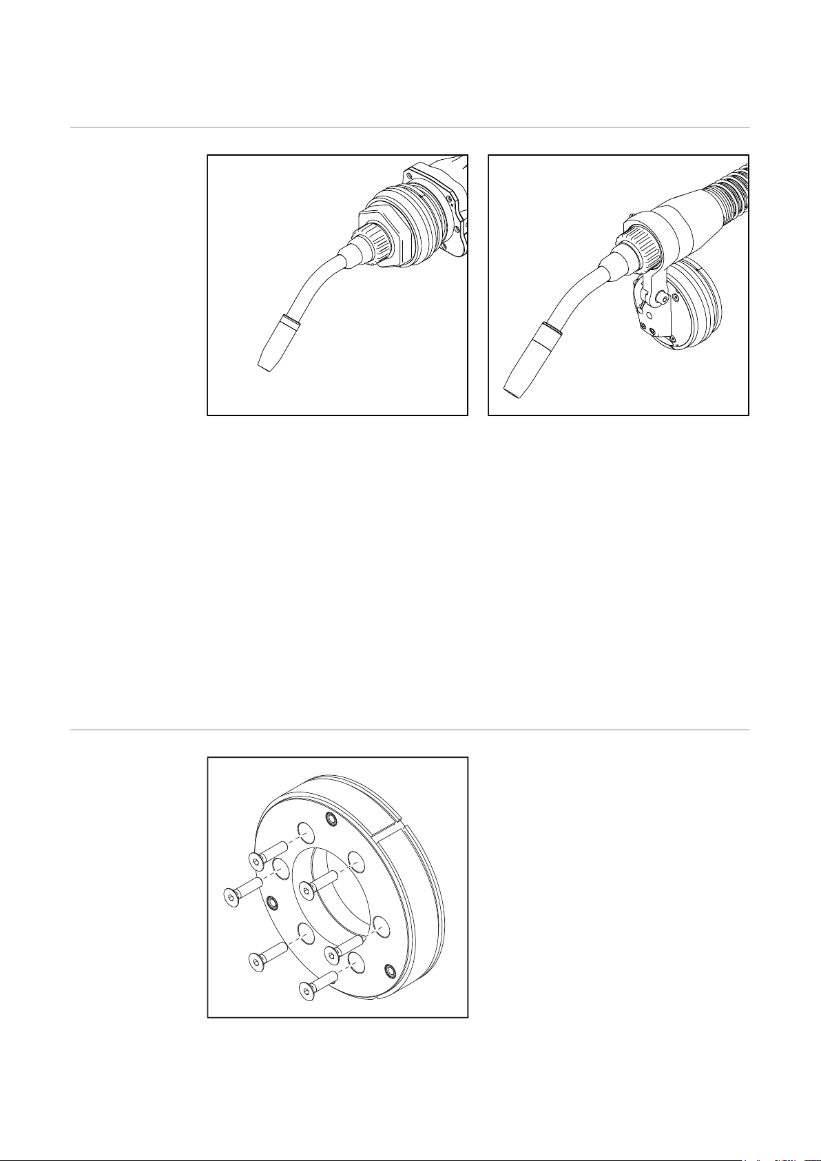
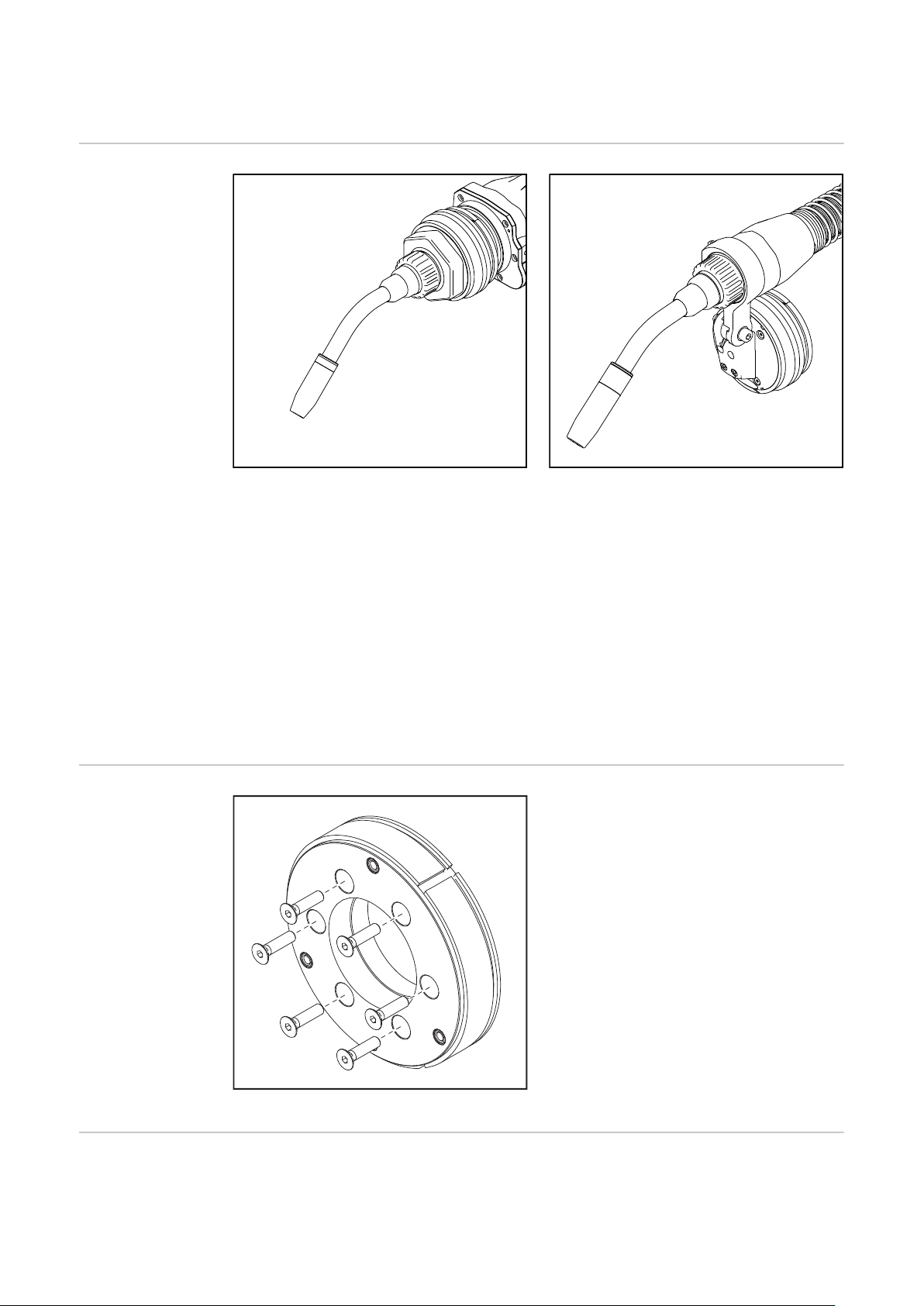
Allgemeines
Am Roboterarm montierte CrashBox /i PAP Am Roboterarm montierte CrashBox /i mit Halte-
Die CrashBox /i ist eine Schutzeinrichtung für den Brennerkörper, die Antriebseinheit, die
Drahtbremse und die Brennerkörper-Kupplung. Im Falle einer Kollision gibt die CrashBox
ein Signal an die Roboter-Steuerung aus, worauf die Roboter-Steuerung den Roboter
sofort stoppt. Auf Grund der Schweißbrenner-Aufnahme der CrashBox wird der
Schweißbrenner und die montierte Peripherie im Falle einer Kollision vor Schäden
geschützt.
schellen-System
Zusätzlich für die
Montage erforderlich
Das Halteschellen-System dient zur Aufnahme von gas- und wassergekühlten RoboterSchweißbrennern. Bei Rohrbogen-Krümmungen von 22°, 36° und 45° positioniert das
Halteschellen-System den Schweißbrenner so, dass der TCP je nach Winkelscheibe in
der 6. Achse oder 45° zur 6. Achse steht.
Für die Montage der CrashBox /i ist ein roboterspezifischer, isolierender Roboterflansch
notwendig.
Abhängig vom jeweiligen Roboter:
- 1 Stk. Roboterflansch mit Schrauben
Roboterflansch gemäß Preisliste
Drehmomente beachten:
Max. Anzugsmoment für Schrauben mit
Festigkeitsklasse 8.8
M4 3,3 Nm
M5 5,0 Nm
M6 6,0 Nm
M8 27,3 Nm
M10 54 Nm
M12 93 Nm
8
Page 9

Gerätekonzept Die CrashBox /i ist speziell für die Montage am Roboterarm konzipiert und für die Auf-
(1)
(2)
(2)(3) (3)
(4) (5) (6)
(1) (2)(3) (4) (5) (6)(2)(3)
nahme von gas- und wassergekühlten Roboter-Schlauchpaketen und Roboter-Antriebseinheiten ausgelegt. Das Schweißbrenner-Schlauchpaket verläuft bei PAP-Systemen
durch die CrashBox und in Folge durch den Roboterarm. Bei konventionellen Robotersystemen verläuft das Schweißbrenner-Schlauchpaket entlang des Roboterarms und ist
an der Halteschelle befestigt.Die magnetische Kupplung ermöglicht bei einem Crash ein
kraftarmes Auslenken mit großem Auslenkweg.
Einsatzgebiete Das Halteschellen-System kann für folgende Push-Roboter-Schlauchpakete verwendet
werden:
- TPS /i Schlauchpakete MHP i G / MHP i W
- TransSteel Schlauchpakete MTG / MTW
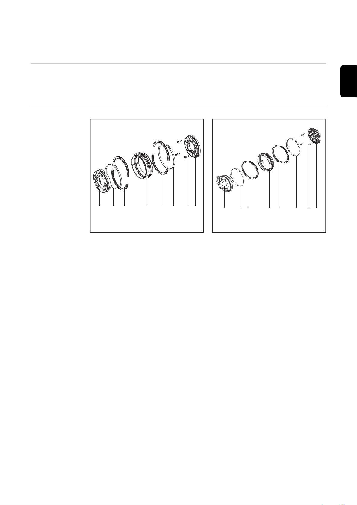
Lieferumfang
DE
Lieferumfang CrashBox /i PAP
Lieferumfang CrashBox /i Standard
(1) CrashBox /i Aufnahme
(2) Ein-Ohr-Klemme *
(3) Verriegelungsring, 2-teilig *
(4) Faltenbalg
(5) Zylinderschrauben M4 x 16 mm
(6) Magnetring
* Bei Auslieferung montiert am Faltenbalg (4)
CrashBox /i Aufnahme (1) und Magnetring (4) vor der Montage am Roboter nicht zusammenbauen. Die Bauteile lassen sich durch den starken Magnetismus nur mehr schwer
lösen.
9
Page 10
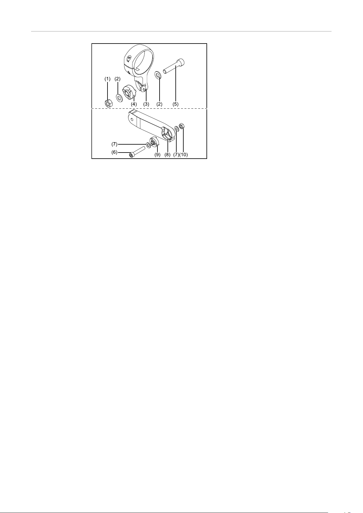
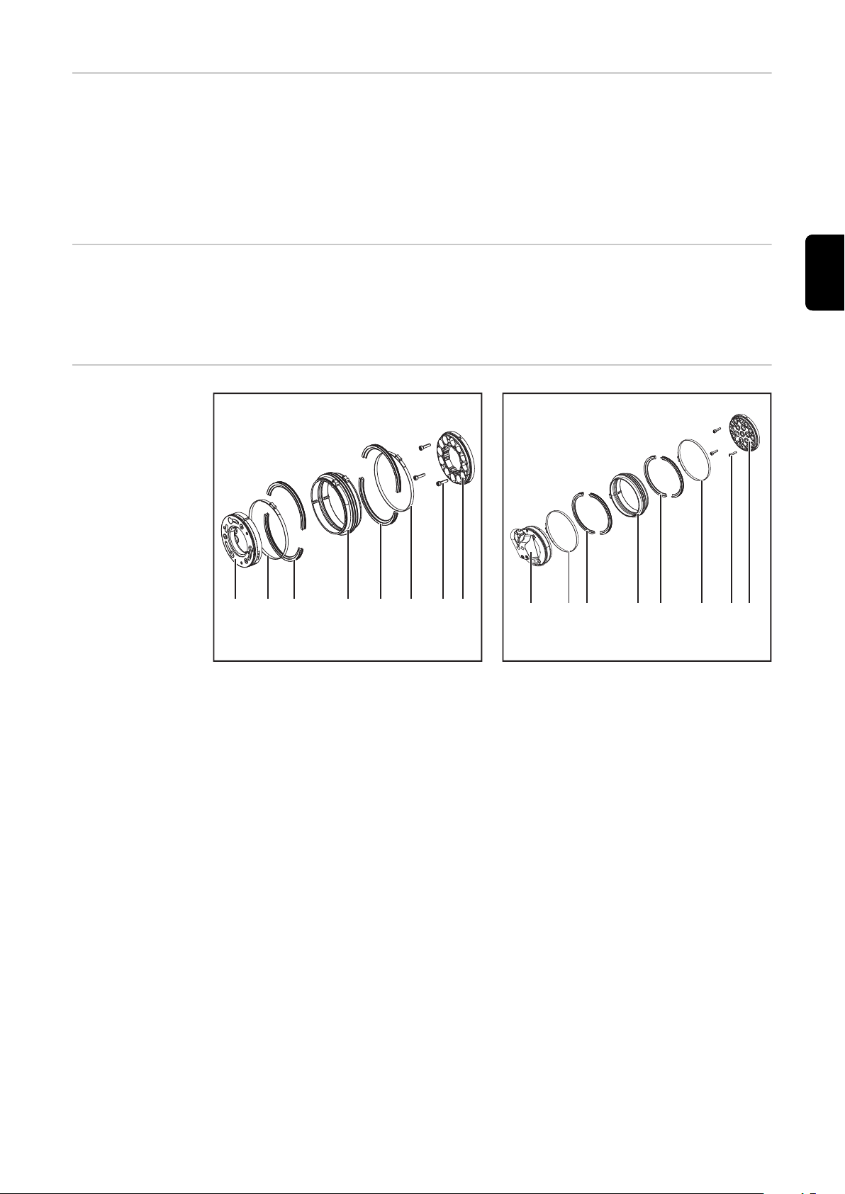
Lieferumfang und
Optionen Halteschellen-System
(1) Sechskant-Mutter M8
(2) Scheibe M8
(3) Halteschelle
(4) Winkelscheibe
(5) Innensechskant-Schraube M8 x 40
mm
Optional (Material für Verlängerung):
(6) Schraube M8 x 40 mm
(7) Scheibe M8
(8) Verlängerung
(9) Winkelscheibe
(10) Sechskant-Mutter M8
10
Page 11
Roboter-Schweißbrenner
DE
Sicherheit
Verbrennungsgefahr durch heißen Rohrbogen, heiße Rohrbogen-Kupplung sowie
andere heiße Schweißbrenner-Komponenten.
Vor Beginn von Arbeiten, am Rohrbogen, der Rohrbogen-Kupplung sowie an allen anderen Schweißbrenner-Komponenten, den Rohrbogen, die Rohrbogen-Kupplung und alle
anderen Schweißbrenner-Komponenten:.
▶
▶
▶
Allgemeines Der Roboter-Schweißbrenner überträgt die
VORSICHT!
auf Zimmertemperatur (+25 °C, +77 °F) abkühlen lassen
elektrisch isolierende und vor Hitze schützende Handschuhe tragen
geeignetes Werkzeug verwenden
Lichtbogen-Leistung auf das Werkstück.
Die TransSteel Schweißbrenner gibt es
wasser- oder gasgekühlt und sie sind für
die Verwendung mit der CrashBox /i konzipiert.
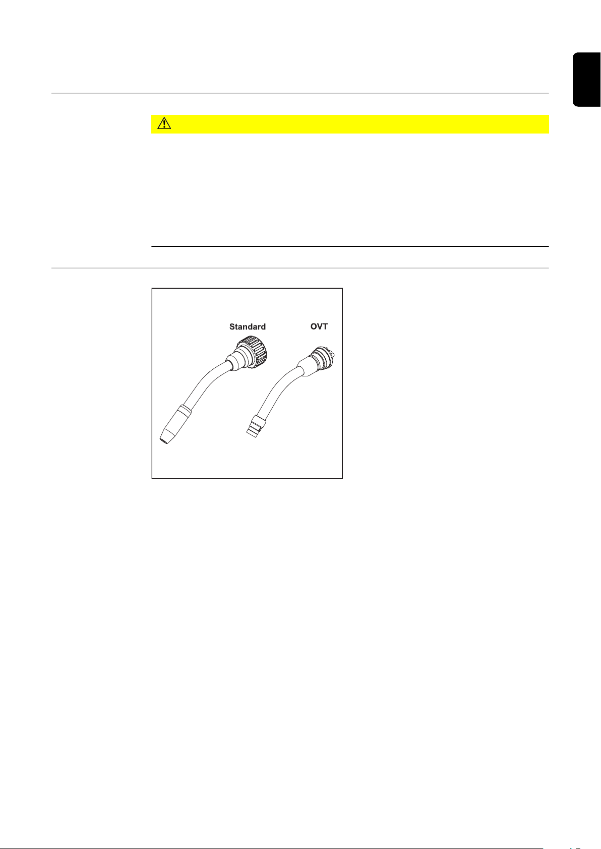
Der Brennerkörper hat eine integrierte Leitung für das Gasdüsen-Positionssuchen.
Standard: mit Verschleißteilen, ohne Kontaktrohr
OVT: Ohne Verschleißteile
11
Page 12

12
Page 13

Installation und Inbetriebnahme
13
Page 14

14
Page 15

Schweißsystem auf konventionellem Roboter montieren
Sicherheit
WARNUNG!
Fehlerhaft durchgeführte Arbeiten können schwerwiegende Personen- und
Sachschäden verursachen.
Nachfolgend beschriebene Tätigkeiten dürfen nur von geschultem Fachpersonal
▶
durchgeführt werden!
Die Bedienungsanleitungen der Systemkomponenten, insbesondere das Kapitel
▶
„Sicherheitsvorschriften“ beachten.
WARNUNG!
Ein elektrischer Schlag kann tödlich sein.
Vor Beginn der nachfolgend beschriebenen Arbeiten:
Netzschalter der Stromquelle in Stellung - O - schalten
▶
Stromquelle vom Netz trennen
▶
sicherstellen, dass die Stromquelle bis zum Abschluss aller Arbeiten vom Netz
▶
getrennt bleibt.
DE
Schweißsystem
TransSteel auf
konventionellem
Roboter montieren
WARNUNG!
Gefahr schwerwiegender Personen- und Sachschäden durch herabfallende
Gegenstände.
Alle nachfolgend beschriebenen Schraubverbindungen:
nach der Montage auf festen Sitz überprüfen
▶
nach außergewöhnlichen Betriebssituationen (beispielsweise: Crash) auf festen Sitz
▶
überprüfen
in regelmäßigen Abständen auf festen Sitz überprüfen
▶
Die einzelnen Komponenten müssen in folgender Reihenfolge am Roboter montiert werden:
1. Drahtvorschub - die Drahtvorschub-Aufnahme und die Seitenarm-Aufnahme
müssen schon vorher montiert werden
2. CrashBox /i
3. Halteschellen-System
4. Schweißbrenner-Schlauchpaket
5. Roboter-Schweißbrenner
6. Verbindungs-Schlauchpaket
15
Page 16

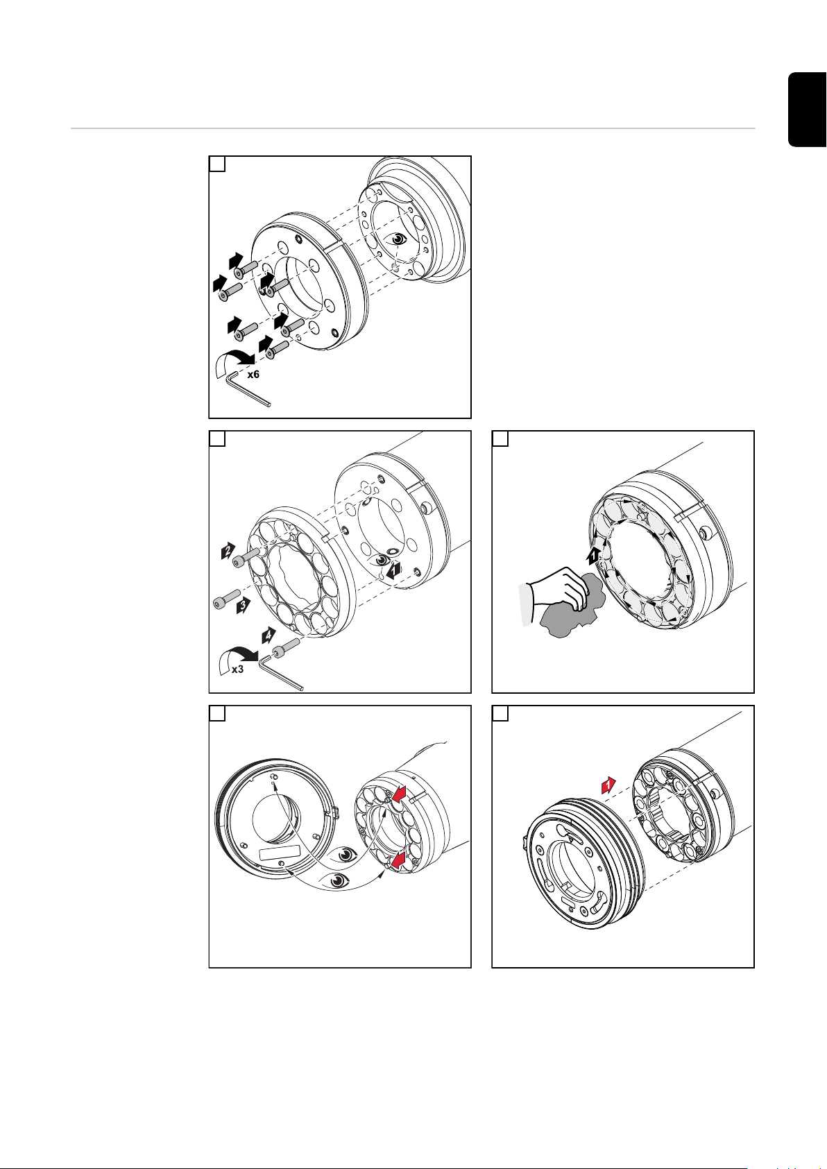
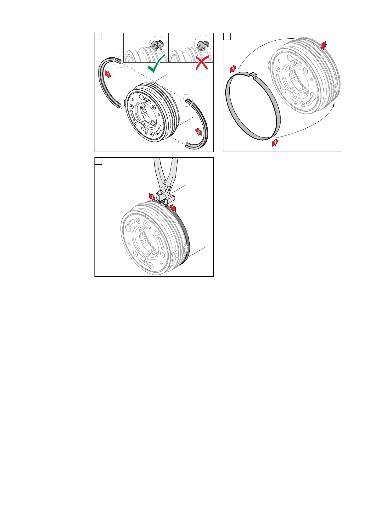
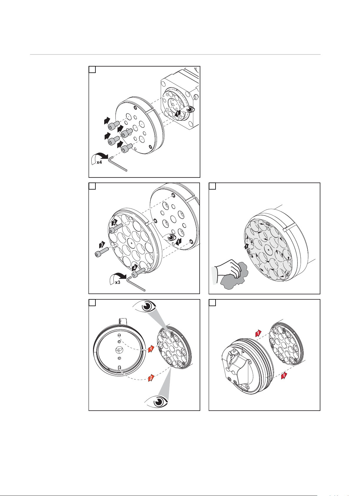
CrashBox /i am Roboter aufbauen
3,3 Nm
CrashBox /i am
Roboter aufbauen
1
2 3
Drehmomente beim Montieren des Roboterflansches beachten:
Max. Anzugsmoment für Schrauben mit
Festigkeitsklasse 8.8
M4 3,3 Nm
M5 5,0 Nm
M6 6,0 Nm
M8 27,3 Nm
M10 54 Nm
M12 93 Nm
4 5
16
Page 17

6 7
8
DE
17
Page 18

Halteschellen-System montieren
12,5°
259
61
320
34,5°
38
- CrashBox /i
- Indexdisk 22°
- Clamp TPS/i
- MHP 700i W R/FSC/0,95m
- MTB 500i W R/22°/L241/H50
- CrashBox /i
- Indexdisk 22°
- Clamp TPS/i
- MHP 400i R /G/FSC/1,45m
- MTB 400i G R /36°/L224/H86
12,5°
235
61
296
48,5°
69
31
12,5°
216
61
277
57,5°
87
49
- CrashBox /i
- Indexdisk 22°
- Clamp TPS/i
- MHP 700i W R/FSC/1,45m
- MTB 500i W R/45°/L209/H107
4,95°
262
61
323
26,95°
34
4
- CrashBox /i
- Indexdisk 36°
- Clamp TPS/i
- MHP 700i W R/FSC/1,25m
- MTB 500i W R/22°/L241/H50
4,95°
242
61
303
40,95°
38
- CrashBox /i
- Indexdisk 36°
- Clamp TPS/i
- MHP 700i W R/FSC/1,25m
- MTB 500i W R/36°/L224/H86
4,95°
226
61
286
49,95°
58
20
- CrashBox /i
- Indexdisk 36°
- Clamp TPS/i
- MHP 700i W R/FSC/0,95m
- MTB 500i W R/45°/L209/H107
0°
261
61
322
22°
58
19
- CrashBox /i
- Indexdisk 45°
- Clamp TPS/i
- MHP 400i R /G/FSC/0,95m
- MTB 400i G R /22°/L241/H50
0°
244
61
305
36°
21
17
- CrashBox /i
- Indexdisk 45°
- Clamp TPS/i
- MHP 400i R /G/FSC/1,25m
- MTB 400i G R /36°/L224/H86
0°
230
61
291
45°
38
- CrashBox /i
- Indexdisk 45°
- Clamp TPS/i
- MHP 700i W R/FSC/1,45m
- MTB 500i W R /45°/L209/H107
Sonder-Anstellwinkel des
Schweißbrenners
Die Anstellung des Schweißbrenners zum Werkstück ist durch die Winkelscheibe in fixe
Winkel eingeteilt. Sonderwinkel sind auf Anfrage möglich.
18
Page 19

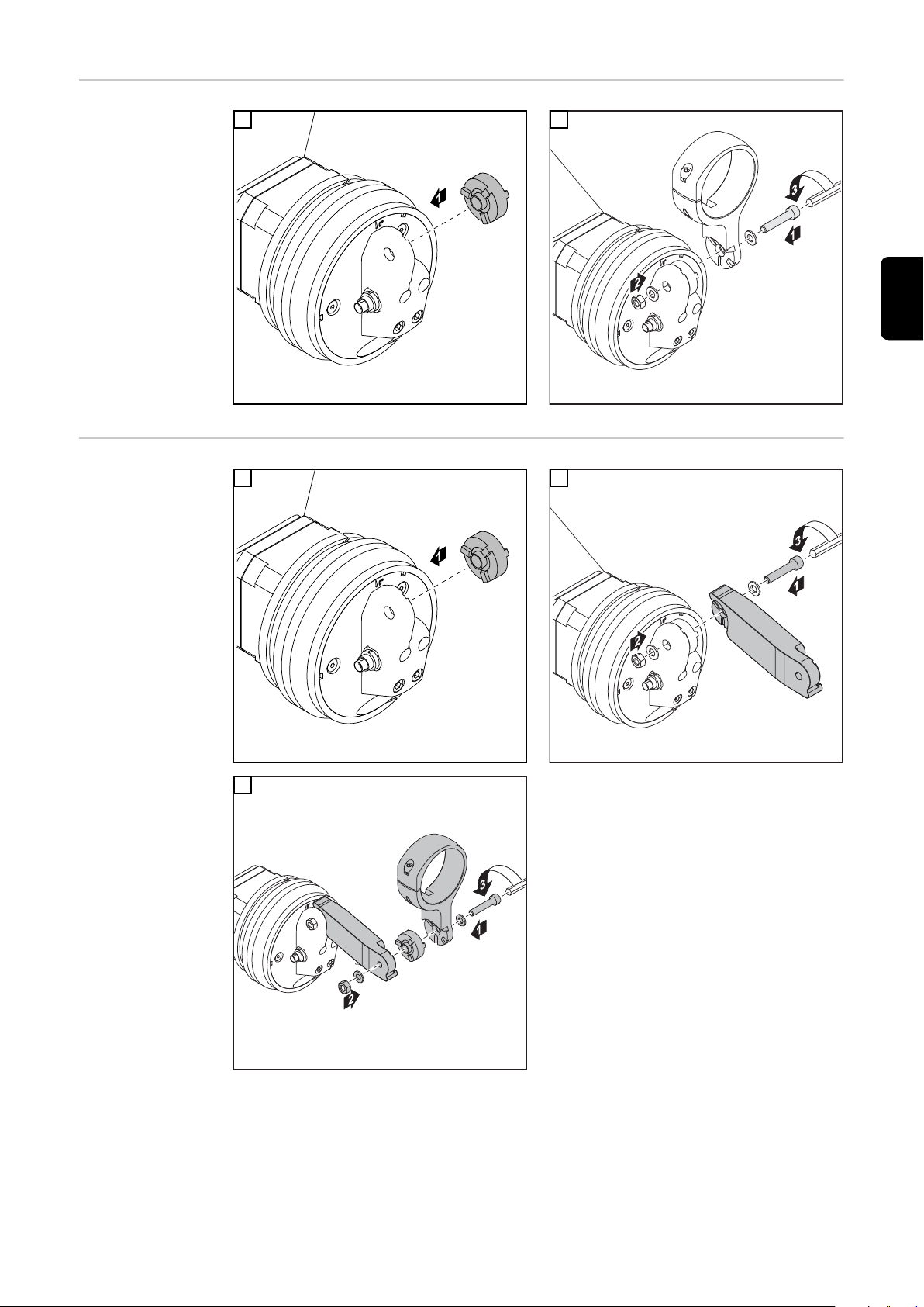
Halteschellen-
42 Nm
42 Nm
42 Nm
System montieren
1
2
DE
HalteschellenSystem mit
Verlängerung
montieren
1
3
2
19
Page 20

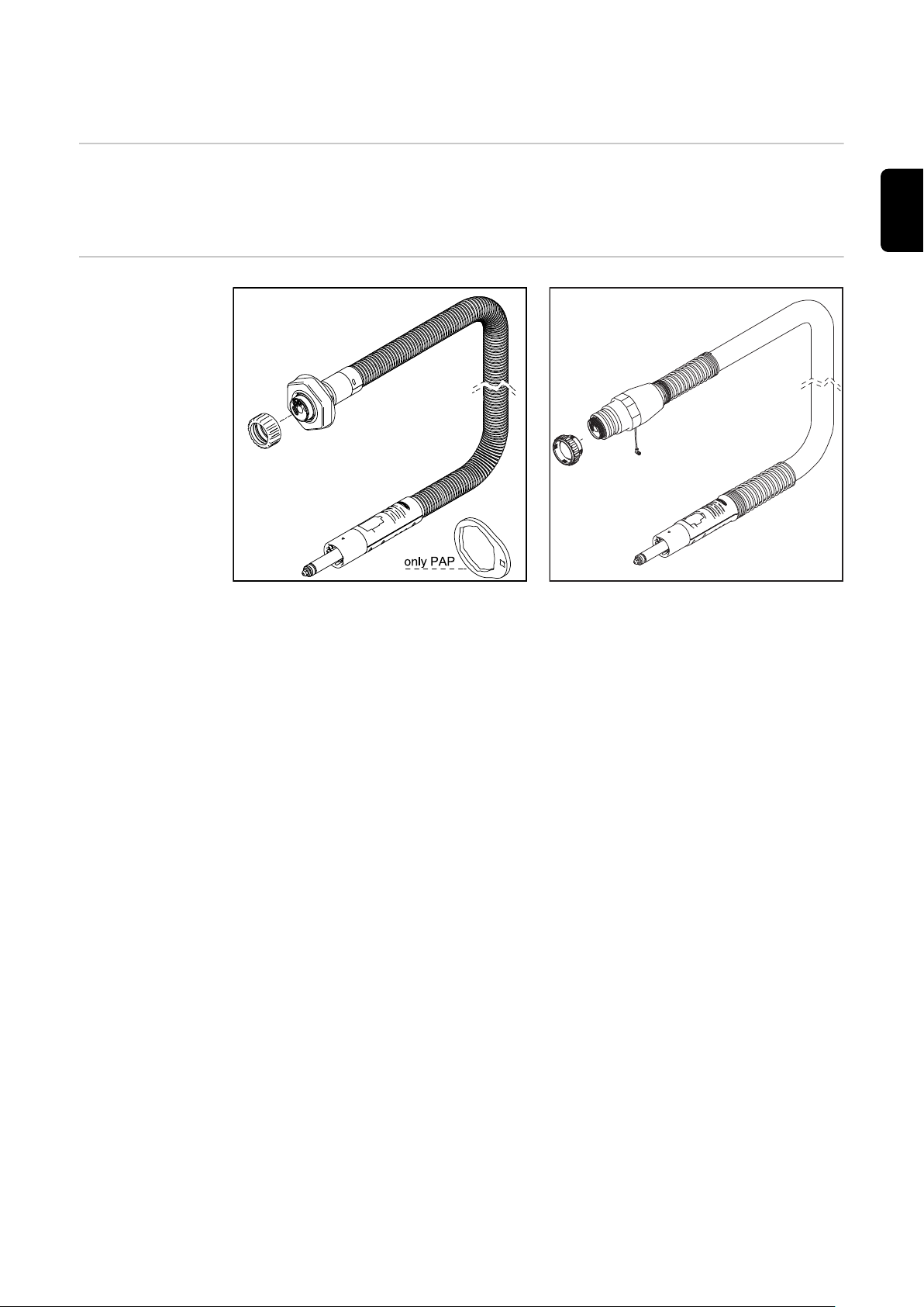
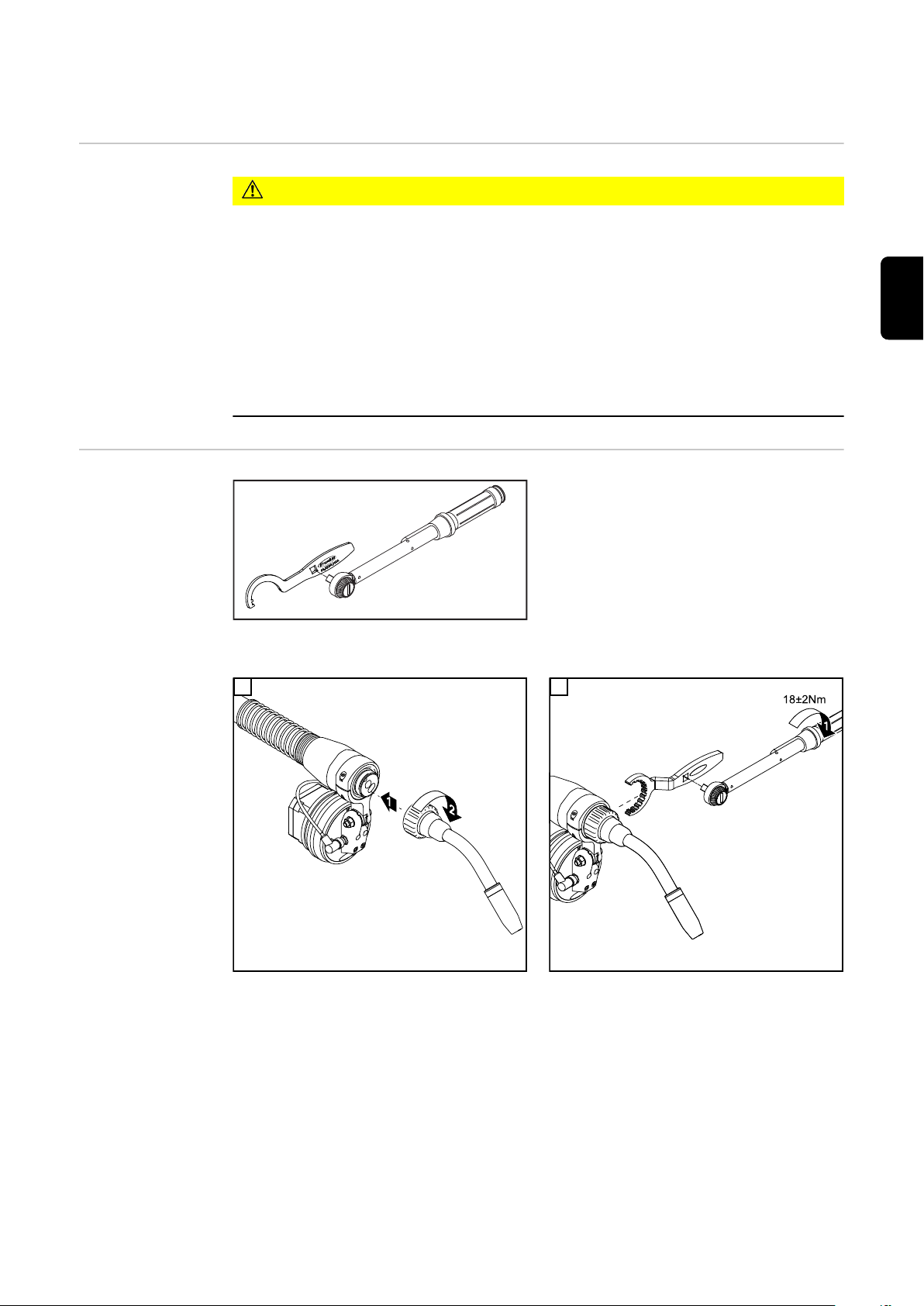
Schlauchpaket MHP G / W montieren
Schlauchpaket
MHP G / W konventionell montieren - Standard
1 2
3 4
20
Page 21

TransSteel Brennerkörper montieren
45,0200,1404
DE
Sicherheit
TransSteel Brennerkörper montieren - Standard
VORSICHT!
Verbrennungsgefahr durch heißen Rohrbogen, heiße Rohrbogen-Kupplung sowie
andere heiße Schweißbrenner-Komponenten.
Vor Beginn von Arbeiten, am Rohrbogen, der Rohrbogen-Kupplung sowie an allen anderen Schweißbrenner-Komponenten, den Rohrbogen, die Rohrbogen-Kupplung und alle
anderen Schweißbrenner-Komponenten:.
auf Zimmertemperatur (+25 °C, +77 °F) abkühlen lassen
▶
elektrisch isolierende und vor Hitze schützende Handschuhe tragen
▶
geeignetes Werkzeug verwenden
▶
Benötigtes Spezialwerkzeug
1 2
21
Page 22

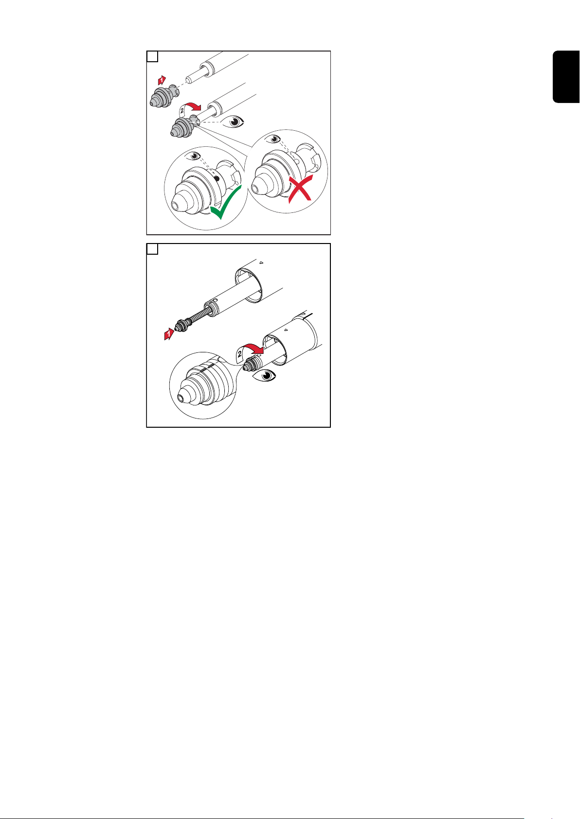
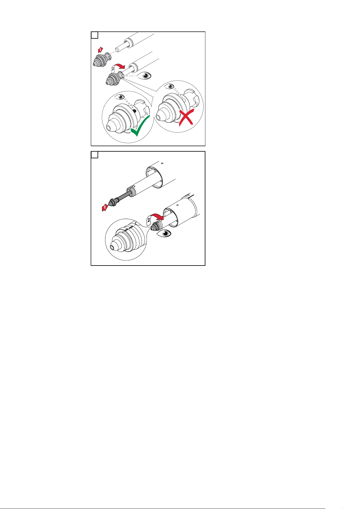
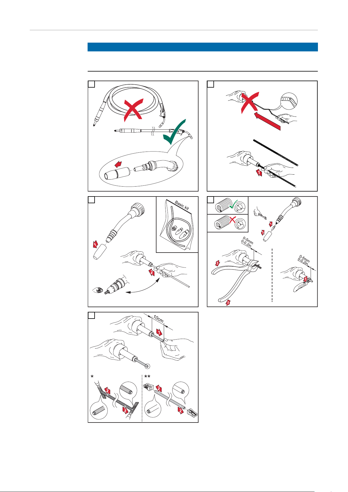
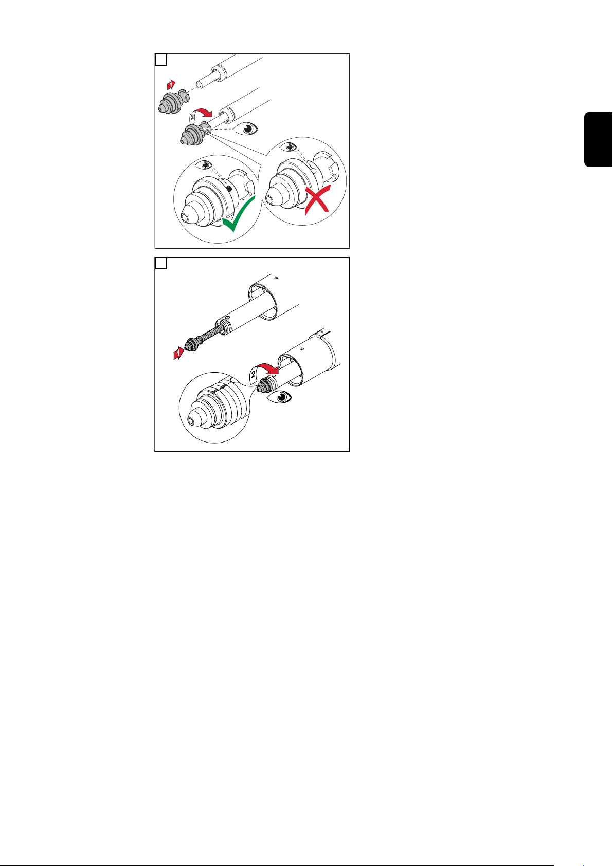
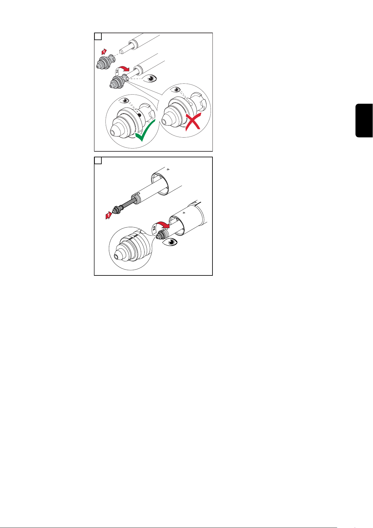
Draht-Führungs-
1
*
**
seele im
SchweißbrennerSchlauchpaket
montieren
HINWEIS!
Damit die Draht-Führungsseele richtig montiert werden kann, das Schlauchpaket
bei der Montage der Draht-Führungsseele gerade auslegen.
1 2
3
5
4
* Stahl Draht-Führungsseele
** Kunststoff Draht-Führungsseele
22
Page 23
***
6
*** den Spann-Nippel bis auf
Anschlag auf die Draht-Führungsseele aufschrauben. Die Draht-
DE
Führungsseele muss durch die
Bohrung im Verschluss zu sehen
sein.
7
23
Page 24

Schweißsystem auf PAP-Roboter montieren
Sicherheit
WARNUNG!
Fehlerhaft durchgeführte Arbeiten können schwerwiegende Personen- und
Sachschäden verursachen.
Nachfolgend beschriebene Tätigkeiten dürfen nur von geschultem Fachpersonal
▶
durchgeführt werden!
Die Bedienungsanleitungen der Systemkomponenten, insbesondere das Kapitel
▶
„Sicherheitsvorschriften“ beachten.
WARNUNG!
Ein elektrischer Schlag kann tödlich sein.
Vor Beginn der nachfolgend beschriebenen Arbeiten:
Netzschalter der Stromquelle in Stellung - O - schalten
▶
Stromquelle vom Netz trennen
▶
sicherstellen, dass die Stromquelle bis zum Abschluss aller Arbeiten vom Netz
▶
getrennt bleibt.
WARNUNG!
Gefahr schwerwiegender Personen- und Sachschäden durch herabfallende
Gegenstände.
Alle nachfolgend beschriebenen Schraubverbindungen:
nach der Montage auf festen Sitz überprüfen
▶
nach außergewöhnlichen Betriebssituationen (beispielsweise: Crash) auf festen Sitz
▶
überprüfen
in regelmäßigen Abständen auf festen Sitz überprüfen
▶
Schweißsystem
TransSteel auf
PAP-Roboter
montieren
Die einzelnen Komponenten müssen in folgender Reihenfolge am Roboter montiert werden:
1. Drahtvorschub - die Drahtvorschub-Aufnahme und die Seitenarm-Aufnahme
müssen schon vorher montiert werden
2. CrashBox /i
3. Schweißbrenner-Schlauchpaket
4. Roboter-Schweißbrenner
5. Verbindungs-Schlauchpaket
24
Page 25
CrashBox /i PAP am Roboter aufbauen
3,3 Nm
DE
CrashBox /i PAP
am Roboter aufbauen
1
2 3
Drehmomente beim Montieren des Roboterflansches beachten:
Max. Anzugsmoment für Schrauben mit
Festigkeitsklasse 8.8
M4 3,3 Nm
M5 5,0 Nm
M6 6,0 Nm
M8 27,3 Nm
M10 54 Nm
M12 93 Nm
4 5
25
Page 26
6 7
8
26
Page 27

Schlauchpaket MHPi / MHP S G/W PAP montieren
45,0200,1404
7*
1
4
5
5
6
3
2
8
Schlauchpaket
Robacta MHP G /
W PAP montieren
Benötigtes Spezialwerkzeug
1 2
DE
3
4
27
Page 28

5 6
7 8
9 10
28
Page 29

Draht-Führungs-
1
*
**
seele im
SchweißbrennerSchlauchpaket
montieren
HINWEIS!
Damit die Draht-Führungsseele richtig montiert werden kann, das Schlauchpaket
bei der Montage der Draht-Führungsseele gerade auslegen.
1 2
DE
3
5
4
* Stahl Draht-Führungsseele
** Kunststoff Draht-Führungsseele
29
Page 30
***
6
*** den Spann-Nippel bis auf
Anschlag auf die Draht-Führungsseele aufschrauben. Die DrahtFührungsseele muss durch die
Bohrung im Verschluss zu sehen
sein.
7
30
Page 31

Pflege, Wartung und Entsorgung
31
Page 32

32
Page 33

Pflege, Wartung und Entsorgung
Allgemeines Das Gerät benötigt unter normalen Betriebsbedingungen nur ein Minimum an Pflege und
Wartung. Das Beachten einiger Punkte ist jedoch unerlässlich, um das Schweißsystem
über Jahre hinweg einsatzbereit zu halten.
DE
Sicherheit
WARNUNG!
Gefahr durch fehlerhaft durchgeführte Arbeiten.
Schwerwiegende Personen- und Sachschäden können die Folge sein.
Alle nachfolgend beschriebenen Arbeiten dürfen nur von geschultem Fachpersonal
▶
durchgeführt werden.
Dieses Dokument vollständig lesen und verstehen.
▶
Sämtliche Bedienungsanleitungen der Systemkomponenten, insbesondere Sicher-
▶
heitsvorschriften vollständig lesen und verstehen.
WARNUNG!
Gefahr durch elektrischen Strom.
Ein elektrischer Schlag kann tödlich sein.
Netzschalter der Stromquelle in Stellung - O - schalten.
▶
Stromquelle vom Netz trennen .
▶
Sicherstellen, dass die Stromquelle bis zum Abschluss aller Arbeiten vom Netz
▶
getrennt bleibt.
Nach dem Öffnen des Gerätes mit Hilfe eines geeigneten Messgerätes sicherstel-
▶
len, dass elektrisch geladene Bauteile (z.B. Kondensatoren) entladen sind.
VORSICHT!
Bei jeder Inbetriebnahme
Gefahr durch heiße Systemkomponenten.
Schwerwiegende Personen- und Sachschäden können die Folge sein.
Vor Beginn der Arbeiten alle heißen Systemkomponenten auf Zimmertemperatur
▶
(+25 °C, +77 °F) abkühlen lassen, beispielsweise:
Heiße Systemkomponenten sind zum Beispiel
- Kühlmittel.
- wassergekühlte Systemkomponenten.
- Antriebsmotor des Drahtvorschubes.
- Alle Schlauchpakete und die Masseverbindung auf Beschädigungen prüfen.
Beschädigte Komponenten austauschen.
- Vorschubrollen und Draht-Führungsseele auf Beschädigungen prüfen. Beschädigte
Komponenten austauschen.
- Drahtförder-Schläuche auf Beschädigungen prüfen. Beschädigte Komponenten austauschen.
- Anpressdruck der Vorschubrollen prüfen und gegebenenfalls einstellen.
- Alle Schraubverbindungen zwischen Roboter, Drahtvorschub-Aufnahme und Drahtvorschub auf festen Sitz prüfen.
33
Page 34

Alle 6 Monate
1.
2.
3.
4.
5.
Erkennen von
defekten Verschleißteilen
VORSICHT!
Gefahr der Beschädigung elektronischer Bauteile.
Elektronische Bauteile nicht aus kurzer Entfernung anblasen.
▶
- Abdeckungen öffnen, Geräte-Seitenteile demontieren und das Geräteinnere mit trockener, reduzierter Druckluft sauberblasen. Nach der Reinigung den Originalzustand
des Gerätes wiederherstellen.
1. Isolierteile
1. abgebrannte Außenkanten, Einkerbungen
2. Düsenstöcke
2. abgebrannte Außenkanten, Einkerbungen
2. stark mit Schweißspritzern behaftet
3. Spritzerschutz
3. abgebrannte Außenkanten, Einkerbungen
4. Kontaktrohre
4. ausgeschliffene (ovale) Drahteintritts- und Drahtaustritts-Bohrungen
4. stark mit Schweißspritzern behaftet
4. Einbrand an der Kontaktrohr-Spitze
5. Gasdüsen
5. stark mit Schweißspritzern behaftet
5. abgebrannte Außenkanten
5. Einkerbungen
MTG d, MTW d Verschleißteile
am Brennerkörper montieren
34
1 2
Page 35

3
** Gasdüse bis auf Anschlag festzie-
hen
DE
Verschleißteile
am Brennerkörper montieren - MTW 700 i
Reinigung des
Schweißbrenners
1 2
1 2
Entsorgung Die Entsorgung nur gemäß den geltenden nationalen und regionalen Bestimmungen
durchführen.
35
Page 36

36
Page 37

Technische Daten
37
Page 38

38
Page 39

Schweißbrenner-Schlauchpaket
Ø
Ø
MHP 500i S R / G / PAP
DE
X / I
(10 min/40° C)
max
M21 (EN 439)
X / I
(10 min/40° C)
max
C1 (EN 439)
[mm (in.)] 0,8-1,6 (.032-.063)
[m (ft.)] 0,96 (3.15) / 1,04 (3.4) / 1,06 (3.48) / 1.075 (3.53) / 1,12 (3.67) / 1,13
* ED = Einschaltdauer
MHP 700 S R / W / PAP
X / I
(10 min/40° C)
max
M21 (EN 439)
X / I
(10 min/40° C)
max
C1 (EN 439)
40 % ED* 500
60 % ED* 450
100 % ED* 360
40 % ED* 500
60 % ED* 450
100 % ED* 360
(3.71) / 1,15 (3.77) / 1,18 (3.87) / 1,19 (3.9) / 1,2 (3.94) / 1,22 (4.0) / 1,31
(4.3) / 1,35 (4.43) / 1,37 (4.5) / 1,4 (4.59) / 1,43 (4.69) / 1,51 (4.95)
-
100 % ED* 700
-
100 % ED* 700
[mm (in.)] 0,8-1,6 (.032-.063)
[m] ([W])
P
Q
p
p
max
min
min
max
[ft.] ([W])
[L/min]
[gal./min]
[bar]
[psi.]
[bar]
[psi.]
* ED = Einschaltdauer
0,96 (1200) / 1,04 (1250) / 1,06 (1250) / 1.075 (1250) / 1,12 (1300) / 1,13
(1300) / 1,15 (1300) / 1,18 (1300) / 1,19 (1300) / 1,2 (1300) / 1,22 (1300) /
1,31 (1350) / 1,35 (1400) / 1,37 (1400) / 1,4 (1400) / 1,43 (1400) / 1,51
(1400)
3.15 (1200) / 3.41 (1250) / 3.48 (1250) / 3.53 (1250) / 3.67 (1300) / 3.71
(1300) / 3.77 (1300) / 3.87 (1300) / 3.9 (1300) / 3.94 (1300) / 4 (1300) / 4.3
(1350) / 4.43 (1400) / 4.5 (1400) / 4.59 (1400) / 4.69 (1400) / 4.95 (1400)
1
0,26
3
43
5
72
39
Page 40

Roboter-Schweißbrenner
Ø
MTB 500S G R MTB 500S G R US
X / I
M21 (EN 439)
X / I
C1 (EN 439)
* ED = Einschaltdauer
(10 min/40° C)
max
(10 min/40° C)
max
[mm (in.)] 0,8-1,6 (.032-.063) 0,8-1,6 (.032-.063)
40 % ED* 500
60 % ED* 450
100 % ED* 360
40 % ED* 500
60 % ED* 450
100 % ED* 360
40 % ED* 500
60 % ED* 450
100 % ED* 360
40 % ED* 500
60 % ED* 450
100 % ED* 360
40
Page 41

Contents
General information 43
Torch hosepack 45
General 45
Scope of supply 45
CrashBox /i 46
General 46
Also required for installation 46
Device concept 46
Application areas 47
Scope of supply 47
Clamp system scope of supply and options 48
Robot welding torch 49
Safety 49
General 49
Installation and commissioning 51
Fitting the welding system to a conventional robot 53
Safety 53
Fitting the TransSteel welding system to a conventional robot 53
Fitting the CrashBox /i to the robot 54
Fitting the CrashBox /i to the robot 54
Fitting the clamp system 56
Special tilt angle for the welding torch 56
Fitting the clamp system 57
Fitting the clamp system with extension 57
Fitting the MHP G / W hosepack 58
Fitting the MHP G / W conventional hosepack - standard 58
Fitting the TransSteel torch body 59
Safety 59
Fitting the TransSteel torch body - Standard 59
Fitting the inner liner inside the torch hosepack 60
Fitting the welding system to a PAP robot 62
Safety 62
Fitting the TransSteel welding system to a PAP robot 62
Installing the CrashBox /i PAP on the robot 63
Installing the CrashBox /i PAP on the robot 63
Fitting the MHPi/MHP S G/W PAP hosepack 65
Fitting the Robacta MHP G/W PAP hosepack 65
Fitting the inner liner inside the torch hosepack 67
EN
Care, maintenance and disposal 69
Care, maintenance and disposal 71
General 71
Safety 71
Every start-up 71
Every 6 months 72
Recognising faulty wearing parts 72
MTG d, MTW d - Fitting wearing parts to the torch body 72
Fitting wearing parts to the torch body - MTW 700 i 73
Cleaning the welding torch 73
Disposal 73
Technical data 75
Torch hosepack 77
Robot welding torch 78
41
Page 42

42
Page 43

General information
43
Page 44

44
Page 45
Torch hosepack
General The MHP 500 S R/G, MHP 700 S R/W hosepack has been designed for gas-cooled/
water-cooled robot applications. It connects the TransSteel Robotics wirefeeders to the
robot welding torches of the TransSteel series.
Scope of supply
EN
MHP PAP hosepack
(1) MHP 500 S R/G, MHP 700 S R/W hosepack
Not supplied:
- Inner liners
- Inlet nozzles
MHP conventional hosepack
45
Page 46
CrashBox /i
General
CrashBox /i PAP fitted to robot arm CrashBox /i fitted to robot arm with clamp system
The CrashBox /i is a protection device for the torch body, the drive unit, the wire brake
and the torch body coupling. In the event of a collision, the CrashBox sends a signal to
the robot control, which stops the robot immediately. The torch holder on the CrashBox
protects the welding torch and the system components fitted from damage should a collision occur.
Also required for
installation
The clamp system is used for holding gas-cooled and water-cooled robot welding torches. With torch body curvatures of 22°, 36° and 45°, the clamp system positions the
welding torch in such a way that the TCP is in the 6th axis or at a 45° angle to the 6th
axis, depending on the torque angle gauge.
A robot-specific, isolated robot flange is required for fitting the CrashBox /i.
Depending on the particular robot:
- 1 x robot flange with screws
Robot flange as per price list
Observe torques:
Max. tightening torque for screws of
strength class 8.8
M4 3.3 Nm
M5 5.0 Nm
M6 6.0 Nm
M8 27.3 Nm
M10 54 Nm
M12 93 Nm
Device concept The CrashBox /i is designed specifically for fitting to the robot arm and for holding gas-
cooled and water-cooled robot hosepacks and robot drive units. For PAP systems, the
torch hosepack runs through the CrashBox and then through the robot arm. In conventio-
46
Page 47
nal robot systems the torch hosepack runs along the robot arm and is attached to the
(1)
(2)
(2)(3) (3)
(4) (5) (6)
(1) (2)(3) (4) (5) (6)(2)(3)
clamp. In the event of a crash, the magnetic coupling smoothly deflects the forces along
a large deflection path.
Application areas The clamp system can be used for the following push robot hosepacks:
- MHP i G / MHP i W TPS /i hosepacks
- MTG/MTW TransSteel hosepacks
Scope of supply
CrashBox /i PAP scope of supply
CrashBox /i Standard scope of supply
(1) CrashBox /i holder
(2) 1-ear clamp *
(3) Locking ring, 2-part *
(4) Bellows
(5) Cheese-head screws, M4 x 16 mm
(6) Magnetic ring
EN
* Delivered fitted to bellows (4)
Do not fit the CrashBox /i holder (1) and magnetic ring (4) together before fitting to the
robot. The components become even more difficult to release due to the strong magnetism.
47
Page 48

Clamp system
scope of supply
and options
(1) M8 hexagon nut
(2) M8 washer
(3) Clamp
(4) Torque angle gauge
(5) M8 x 40 mm Allen screw
Optional (material for extension):
(6) M8 x 40 mm screw
(7) M8 washer
(8) Extension
(9) Torque angle gauge
(10) M8 hexagon nut
48
Page 49

Robot welding torch
Safety
Risk of burns from hot torch body, hot torch body coupling and other hot welding
torch components.
Before starting work on the torch body, the torch body coupling and all other welding
torch components:
▶
▶
▶
General The robot welding torch transmits the arc
CAUTION!
Allow the torch body, torch body coupling and all other welding torch components to
cool down to room temperature (+25 °C, +77 °F)
Wear electrically insulated and heat protective gloves
Use a suitable tool
power to the workpiece. The gas-cooled or
water-cooled TransSteel welding torch is
designed for use with the CrashBox /i.
The torch body has an integrated lead for
gas nozzle touch sensing.
Standard: with wearing parts, without contact tip
EN
OVT: without wearing parts
49
Page 50

50
Page 51

Installation and commissioning
51
Page 52

52
Page 53

Fitting the welding system to a conventional robot
Safety
WARNING!
Work that is carried out incorrectly can cause serious injury or damage.
The following activities may only be carried out by trained and qualified personnel.
▶
The Operating Instructions for system components, particularly the chapter entitled
▶
"Safety rules", must be observed.
WARNING!
An electric shock can be fatal.
Before starting the work described below:
Turn the power source mains switch to the "O" position
▶
Disconnect the power source from the mains
▶
Ensure that the power source remains disconnected from the mains until all work
▶
has been completed.
WARNING!
Risk of serious injury and damage from articles being dropped.
For all of the screw connections referred to below:
Check after fitting to ensure they are tight
▶
Check following an unusual operating situation (e.g. crash) to ensure they are tight
▶
Check regularly to ensure they are tight
▶
EN
Fitting the TransSteel welding
system to a conventional robot
Individual components must be fitted to the robot in the following order:
1. Wirefeeder - the wirefeeder holder and the side arm holder must be fitted first
2. CrashBox /i
3. Clamp system
4. Torch hosepack
5. Robot welding torch
6. Interconnecting hosepack
53
Page 54
Fitting the CrashBox /i to the robot
3,3 Nm
Fitting the CrashBox /i to the
robot
1
2 3
Observe the torques when fitting the robot
flange:
Max. tightening torque for screws of
strength class 8.8
M4 3.3 Nm
M5 5.0 Nm
M6 6.0 Nm
M8 27.3 Nm
M10 54 Nm
M12 93 Nm
4 5
54
Page 55

6 7
8
EN
55
Page 56

Fitting the clamp system
12,5°
259
61
320
34,5°
38
- CrashBox /i
- Indexdisk 22°
- Clamp TPS/i
- MHP 700i W R/FSC/0,95m
- MTB 500i W R/22°/L241/H50
- CrashBox /i
- Indexdisk 22°
- Clamp TPS/i
- MHP 400i R /G/FSC/1,45m
- MTB 400i G R /36°/L224/H86
12,5°
235
61
296
48,5°
69
31
12,5°
216
61
277
57,5°
87
49
- CrashBox /i
- Indexdisk 22°
- Clamp TPS/i
- MHP 700i W R/FSC/1,45m
- MTB 500i W R/45°/L209/H107
4,95°
262
61
323
26,95°
34
4
- CrashBox /i
- Indexdisk 36°
- Clamp TPS/i
- MHP 700i W R/FSC/1,25m
- MTB 500i W R/22°/L241/H50
4,95°
242
61
303
40,95°
38
- CrashBox /i
- Indexdisk 36°
- Clamp TPS/i
- MHP 700i W R/FSC/1,25m
- MTB 500i W R/36°/L224/H86
4,95°
226
61
286
49,95°
58
20
- CrashBox /i
- Indexdisk 36°
- Clamp TPS/i
- MHP 700i W R/FSC/0,95m
- MTB 500i W R/45°/L209/H107
0°
261
61
322
22°
58
19
- CrashBox /i
- Indexdisk 45°
- Clamp TPS/i
- MHP 400i R /G/FSC/0,95m
- MTB 400i G R /22°/L241/H50
0°
244
61
305
36°
21
17
- CrashBox /i
- Indexdisk 45°
- Clamp TPS/i
- MHP 400i R /G/FSC/1,25m
- MTB 400i G R /36°/L224/H86
0°
230
61
291
45°
38
- CrashBox /i
- Indexdisk 45°
- Clamp TPS/i
- MHP 700i W R/FSC/1,45m
- MTB 500i W R /45°/L209/H107
Special tilt angle
for the welding
torch
The positioning of the welding torch in relation to the workpiece is divided into fixed
angles by the torque angle gauge. Special angles are available on request.
56
Page 57

Fitting the clamp
42 Nm
42 Nm
42 Nm
system
1
2
EN
Fitting the clamp
system with
extension
1
3
2
57
Page 58

Fitting the MHP G / W hosepack
Fitting the MHP
G / W conventional hosepack standard
1 2
3 4
58
Page 59

Fitting the TransSteel torch body
45,0200,1404
Safety
Fitting the TransSteel torch body Standard
CAUTION!
Risk of burns from hot torch body, hot torch body coupling and other hot welding
torch components.
Before starting work on the torch body, the torch body coupling and all other welding
torch components:
Allow the torch body, torch body coupling and all other welding torch components to
▶
cool down to room temperature (+25 °C, +77 °F)
Wear electrically insulated and heat protective gloves
▶
Use a suitable tool
▶
Special tool required
EN
1 2
59
Page 60
Fitting the inner
1
*
**
liner inside the
torch hosepack
NOTE!
Ensure that the hosepack is straight when fitting the inner liner, otherwise the liner
might not be inserted correctly.
1 2
3
5
4
* Steel inner liner
** Plastic inner liner
60
Page 61
***
6
*** Screw the clamping nipple onto the
inner liner as far as it will go. The
inner liner must be visible through
the hole in the cap.
EN
7
61
Page 62

Fitting the welding system to a PAP robot
Safety
WARNING!
Work that is carried out incorrectly can cause serious injury or damage.
The following activities may only be carried out by trained and qualified personnel.
▶
The Operating Instructions for system components, particularly the chapter entitled
▶
"Safety rules", must be observed.
WARNING!
An electric shock can be fatal.
Before starting the work described below:
Turn the power source mains switch to the "O" position
▶
Disconnect the power source from the mains
▶
Ensure that the power source remains disconnected from the mains until all work
▶
has been completed.
WARNING!
Risk of serious injury and damage from articles being dropped.
For all of the screw connections referred to below:
Check after fitting to ensure they are tight
▶
Check following an unusual operating situation (e.g. crash) to ensure they are tight
▶
Check regularly to ensure they are tight
▶
Fitting the TransSteel welding
system to a PAP
robot
Individual components must be fitted to the robot in the following order:
1. Wirefeeder - the wirefeeder holder and the side arm holder must be fitted first
2. CrashBox /i
3. Torch hosepack
4. Robot welding torch
5. Interconnecting hosepack
62
Page 63

Installing the CrashBox /i PAP on the robot
3,3 Nm
Installing the
CrashBox /i PAP
on the robot
1
2 3
Observe the torques when fitting the robot
flange:
Max. tightening torque for screws of
strength class 8.8
M4 3.3 Nm
M5 5.0 Nm
M6 6.0 Nm
M8 27.3 Nm
M10 54 Nm
M12 93 Nm
EN
4 5
63
Page 64

6 7
8
64
Page 65

Fitting the MHPi/MHP S G/W PAP hosepack
45,0200,1404
7*
1
4
5
5
6
3
2
8
Fitting the
Robacta MHP
G/W PAP
hosepack
Special tool required
1 2
EN
3
4
65
Page 66

5 6
7 8
9 10
66
Page 67

Fitting the inner
1
*
**
liner inside the
torch hosepack
NOTE!
Ensure that the hosepack is straight when fitting the inner liner, otherwise the liner
might not be inserted correctly.
1 2
3
EN
4
5
* Steel inner liner
** Plastic inner liner
67
Page 68

***
6
*** Screw the clamping nipple onto the
inner liner as far as it will go. The
inner liner must be visible through
the hole in the cap.
7
68
Page 69

Care, maintenance and disposal
69
Page 70

70
Page 71

Care, maintenance and disposal
General Under normal operating conditions, the device requires only a minimum of care and
maintenance. However, it is vital to observe some important points to ensure the welding
system remains in a usable condition for many years.
EN
Safety
WARNING!
Danger due to work that has been carried out incorrectly.
This can result in severe personal injury and damage to property.
All the work described below must only be carried out by trained and qualified per-
▶
sonnel.
Fully read and understand this document.
▶
Fully read and understand all the Operating Instructions for the system components,
▶
especially the safety rules.
WARNING!
Danger from electric current.
An electric shock can be fatal.
Turn the power source mains switch to the "O" position.
▶
Disconnect the power source from the mains.
▶
Ensure that the power source remains disconnected from the mains until all work
▶
has been completed.
After opening the device, use a suitable measuring instrument to check that electri-
▶
cally charged components (e.g. capacitors) have been discharged.
CAUTION!
Danger from hot system components.
This can result in severe personal injury and damage to property.
Before starting work, allow all hot system components to cool down to room tempe-
▶
rature (+25 °C, +77 °F). For example:
Examples of hot system components include
- Coolant.
- Water-cooled system components.
- Wirefeeder drive motor.
Every start-up - Check all hosepacks and the ground earth connection for damage. Replace any
damaged components.
- Check feed rollers and inner liners for signs of damage. Replace any damaged components.
- Check the wirefeeding hoses for damage. Replace any damaged components.
- Check contact pressure of feed rollers and adjust if necessary.
- Check that all screw connections between the robot, wirefeeder holder and wirefeed unit are secure.
71
Page 72

Every 6 months
1.
2.
3.
4.
5.
Recognising
faulty wearing
parts
CAUTION!
Danger of damage to electronic components.
Do not bring the air nozzle too close to electronic components.
▶
- Open covers, remove device side panels and clean inside of device with dry reduced compressed air. After cleaning, restore device to its original state.
1. Insulating parts
1. Burned-off outside edges, notches
2. Nozzle fittings
2. Burned-off outside edges, notches
2. Heavily covered in welding spatter
3. Spatter guard
3. Burned-off outside edges, notches
4. Contact tips
4. Worn-out (oval) wire entry and wire exit holes
4. Heavily covered in welding spatter
4. Fusion penetration on the tip of the contact tube
5. Gas nozzles
5. Heavily covered in welding spatter
5. Burned-off outside edges
5. Notches
MTG d, MTW d Fitting wearing
parts to the torch
body
1 2
72
Page 73

3
** Screw on and tighten the gas
nozzle as far as it will go
EN
Fitting wearing
parts to the torch
body - MTW 700 i
Cleaning the welding torch
1 2
1 2
Disposal Dispose of in accordance with the applicable national and local regulations.
73
Page 74

74
Page 75

Technical data
75
Page 76

76
Page 77

Torch hosepack
Ø
Ø
MHP 500i S R / G / PAP
X / I
(10 min/40 °C)
max
M21 (EN 439)
X / I
(10 min/40 °C)
max
C1 (EN 439)
[mm (in.)] 0.8-1.6 (0.032-0.063)
[m (ft.)] 0.96 (3.15) / 1.04 (3.4) / 1.06 (3.48) / 1,075 (3.53) / 1.12 (3.67) / 1.13
* D.C. = Duty cycle
MHP 700 S R / W / PAP
X / I
(10 min/40 °C)
max
M21 (EN 439)
X / I
(10 min/40 °C)
max
C1 (EN 439)
40% D.C.* 500
60% D.C.* 450
100% D.C.* 360
40% D.C.* 500
60% D.C.* 450
100% D.C.* 360
(3.71) / 1.15 (3.77) / 1.18 (3.87) / 1.19 (3.9) / 1.2 (3.94) / 1.22 (4.0) / 1.31
(4.3) / 1.35 (4.43) / 1.37 (4.5) / 1.4 (4.59) / 1.43 (4.69) / 1.51 (4.95)
-
100% D.C.* 700
-
100% D.C.* 700
EN
[mm (in.)] 0.8-1.6 (0.032-0.063)
[m] ([W])
P
Q
p
p
max
min
min
max
[ft.] ([W])
[L/min]
[gal./min]
[bar]
[psi]
[bar]
[psi]
* D.C. = Duty cycle
0.96 (1200) / 1.04 (1250) / 1.06 (1250) / 1.075 (1250) / 1.12 (1300) / 1.13
(1300) / 1.15 (1300) / 1.18 (1300) / 1.19 (1300) / 1.2 (1300) / 1.22 (1300) /
1.31 (1350) / 1.35 (1400) / 1.37 (1400) / 1.4 (1400) / 1.43 (1400) / 1.51
(1400)
3.15 (1200) / 3.41 (1250) / 3.48 (1250) / 3.53 (1250) / 3.67 (1300) / 3.71
(1300) / 3.77 (1300) / 3.87 (1300) / 3.9 (1300) / 3.94 (1300) / 4 (1300) / 4.3
(1350) / 4.43 (1400) / 4.5 (1400) / 4.59 (1400) / 4.69 (1400) / 4.95 (1400)
1
0.26
3
43
5
72
77
Page 78

Robot welding torch
Ø
MTB 500S G R MTB 500S G R US
X / I
M21 (EN 439)
X / I
C1 (EN 439)
* D.C. = Duty cycle
(10 min/40° C)
max
(10 min/40° C)
max
[mm (in.)] 0,8-1,6 (.032-.063) 0,8-1,6 (.032-.063)
40 % D.C.* 500
60 % D.C.* 450
100 % D.C.* 360
40 % D.C.* 500
60 % D.C.* 450
100 % D.C.* 360
40 % D.C.* 500
60 % D.C.* 450
100 % D.C.* 360
40 % D.C.* 500
60 % D.C.* 450
100 % D.C.* 360
78
Page 79

Tabla de contenido
Información general 81
Juego de cables de la antorcha 83
Generalidades 83
Volumen de suministro 83
CrashBox /i 84
Generalidades 84
Adicionalmente se requiere para el montaje: 84
Concepto del sistema 85
Campos de aplicación 85
Volumen de suministro 85
Volumen de suministro y opciones del sistema de bridas 86
Antorcha de robot 87
Seguridad 87
Generalidades 87
Instalación y puesta en servicio 89
Montar el sistema de soldadura en un robot convencional 91
Seguridad 91
Montar el sistema de soldadura TransSteel en un robot convencional 91
Montar el anticolisión /i en el robot 92
Montar el anticolisión /i en el robot 92
Montar el sistema de abrazaderas de sujeción 94
Ángulo de incidencia especial de la antorcha de soldadura 94
Montar el sistema de bridas 95
Montar el sistema de bridas con extensión 95
Montar el juego de cables MHP G / W 96
Montar el juego de cables MHP G / W convencional - Estándar 96
Montar el cuello antorcha TransSteel 97
Seguridad 97
Montar el cuello antorcha TransSteel - Estándar 97
Montar la sirga de guía de hilo en el juego de cables de la antorcha 98
Montar el sistema de soldadura en un robot PAP 100
Seguridad 100
Montar el sistema de soldadura TransSteel en un robot PAP 100
Montar el anticolisión /i PAP en el robot 101
Montar el anticolisión /i PAP en el robot 101
Montar el juego de cables MHPi / MHP S G/W PAP 103
Montar el juego de cables Robacta MHP G / W PAP 103
Montar la sirga de guía de hilo en el juego de cables de la antorcha 105
ES
Cuidado, mantenimiento y eliminación 107
Cuidado, mantenimiento y eliminación 109
Generalidades 109
Seguridad 109
Con cada puesta en servicio 109
Cada 6 meses 110
Detectar consumibles defectuosos 110
MTG d, MTW d - Montar los consumibles en el cuello antorcha 110
Montar los consumibles en el cuello antorcha - MTW 700 i 111
Limpieza de antorcha de soldadura 111
Eliminación 111
Datos técnicos 113
Juego de cables de la antorcha 115
Antorcha de robot 116
79
Page 80

80
Page 81

Información general
81
Page 82

82
Page 83

Juego de cables de la antorcha
Generalidades El juego de cables MHP 400 S R/G, MHP 700 S R/W ha sido concebido para aplicacio-
nes de robot refrigerado por gas/agua. Sirve para unir los avances de hilo de TransSteel
Robotics a las antorchas de robot de la serie TransSteel.
Volumen de
suministro
Juego de cables MHP PAP
(1) Juego de cables MHP 500 S R/G, MHP 700 S R/W
Los siguientes elementos no forman parte del volumen de suministro:
- Sirgas de guía de hilo
- Bocas de carga
Juego de cables MHP convencional
ES
83
Page 84

CrashBox /i
Generalidades
Anticolisión /i PAP montado en el brazo de robot Anticolisión /i con sistema de bridas montado en el
El anticolisión /i es un dispositivo de protección para el cuello antorcha, la unidad de
impulsión, el freno de hilo y el acoplamiento del cuello antorcha. En caso de colisión, el
anticolisión emite una señal al control del robot y este hace que el robot se detenga de
inmediato. Gracias al alojamiento de la antorcha de soldadura del anticolisión, los componentes del sistema montados y la antorcha de soldadura quedan protegidos frente a
daños en caso de colisión.
brazo de robot
Adicionalmente
se requiere para
el montaje:
El sistema de bridas sirve para alojar las antorchas de robot refrigeradas por gas y por
agua. En caso de dobladuras de cuello antorcha de 22°, 36° y 45°, el sistema de bridas
posiciona la antorcha de soldadura de tal modo que el TCP se encuentra en función del
disco graduado en el 6.º eje o a 45° con respecto al 6.º eje.
Para el montaje del anticolisión /i se requiere una brida aislante específica para el robot.
En función del robot correspondiente:
- 1 ejemplar de brida de robot con tornillos
Brida de robot según la lista de precios
Tener en cuenta los pares:
Máx. par de apriete para tornillos de la
clase de resistencia 8.8
M4 3,3 Nm
M5 5,0 Nm
M6 6,0 Nm
M8 27,3 Nm
M10 54 Nm
M12 93 Nm
84
Page 85
Concepto del sis-
(1)
(2)
(2)(3) (3)
(4) (5) (6)
(1) (2)(3) (4) (5) (6)(2)(3)
tema
El anticolisión /i ha sido concebido especialmente para el montaje en el brazo de robot y
configurado para juegos de cables de robot y paquetes de mangueras de robot refrigeradas por gas y por agua. El juego de cables de la antorcha pasa en caso de sistemas
PAP por el anticolisión y a continuación por el brazo de robot. En sistemas de robots
convencionales el juego de cables de la antorcha transcurre por el brazo de robot y está
fijado en la brida. El acoplamiento magnético permite en caso de una colisión efectuar
una desviación con poca aplicación de fuerza con un gran trayecto de desviación.
Campos de aplicación
Volumen de
suministro
El sistema de bridas de sujeción puede utilizarse para los siguientes juegos de cables
de robot push:
- TPS /i juegos de cables MHP i G / MHP i W
- TransSteel juegos de cables MTG / MTW
Volumen de suministro anticolisión /i PAP
Volumen de suministro anticolisión /i Estándar
ES
(1) Alojamiento del anticolisión /i
(2) Abrazadera de una orejeta *
(3) Anillo de bloqueo, 2 piezas *
(4) Fuelle
(5) Tornillos cilíndricos M4 x 16 mm
(6) Anillo magnético
* Se entrega montado en el fuelle (4)
No montar el alojamiento del anticolisión /i (1) ni el anillo magnético (4) antes del montaje en el robot. Debido al intenso magnetismo resulta muy difícil separar los componentes.
85
Page 86

Volumen de
suministro y
opciones del sistema de bridas
(1) Tuerca hexagonal M8
(2) Arandela M8
(3) Brida
(4) Disco graduado
(5) Tornillo cabeza Allen M8 x 40 mm
Opcional (material para la extensión):
(6) Tornillo M8 x 40 mm
(7) Arandela M8
(8) Extensión
(9) Disco graduado
(10) Tuerca hexagonal M8
86
Page 87

Antorcha de robot
Seguridad
Peligro de quemaduras originado por el cuello antorcha caliente, el acoplamiento
de cuello de antorcha, así como otros componentes de la antorcha de soldadura
calientes.
Antes de comenzar los trabajos en el cuello antorcha, en el acoplamiento de cuello
antorcha, así como en todos los demás componentes de la antorcha de soldadura, dejar
que el cuello antorcha, el acoplamiento de cuello antorcha, así como todos los demás
componentes de la antorcha de soldadura:
▶
▶
▶
Generalidades La antorcha de robot transmite la potencia
¡PRECAUCIÓN!
Se enfríen a temperatura ambiente (+25 °C, +77 °F)
Llevar guantes aislantes contra componentes eléctricos y que protejan del calor
Utilizar herramientas adecuadas
de arco voltaico a la pieza de trabajo. Las
antorchas de soldadura TransSteel están
disponibles con refrigeración por agua o
por gas y han sido concebidas para su
uso con el anticolisión /i.
El cuello antorcha tiene una línea integrada para la búsqueda de posición de
toberas de gas.
ES
Estándar: con consumibles, sin tubo de
contacto
OVT: sin consumibles
87
Page 88

88
Page 89

Instalación y puesta en servicio
89
Page 90

90
Page 91

Montar el sistema de soldadura en un robot convencional
Seguridad
¡PELIGRO!
Los trabajos realizados de forma defectuosa pueden causar graves daños personales y materiales.
¡Las actividades descritas a continuación solo deben ser realizadas por personal
▶
técnico debidamente instruido!
Tener en cuenta los manuales de normas de los componentes del sistema, en parti-
▶
cular el capítulo "Normas de seguridad".
¡PELIGRO!
Las descargas eléctricas pueden ser mortales.
Antes de comenzar los trabajos descritos a continuación:
Poner el interruptor de red de la fuente de corriente en la posición - O -.
▶
Separar la fuente de corriente de la red.
▶
Asegurar que la fuente de corriente permanezca separada de la red hasta que se
▶
hayan finalizado todos los trabajos.
¡PELIGRO!
Peligro de graves daños personales y materiales originado por la caída o de objetos.
Todas las uniones atornilladas descritas a continuación:
Comprobar el asiento firme después del montaje
▶
Comprobar el asiento firme después de situaciones de servicio extraordinarias (por
▶
ejemplo: colisión)
Comprobar el asiento firme periódicamente
▶
ES
Montar el sistema
de soldadura
TransSteel en un
robot convencional
Los diferentes componentes se deben montar en el robot siguiendo este orden de
secuencia:
1. El avance de hilo, el soporte devanadora y el alojamiento del brazo lateral se deben
montar previamente
2. Anticolisión /i
3. Sistema de bridas
4. Juego de cables de la antorcha
5. Antorcha de robot
6. Juego de cables de interconexión
91
Page 92

Montar el anticolisión /i en el robot
3,3 Nm
Montar el anticolisión /i en el
robot
1
2 3
Tener en cuenta los pares al montar la
brida de robot:
Máx. par de apriete para tornillos de la
clase de resistencia 8.8
M4 3,3 Nm
M5 5,0 Nm
M6 6,0 Nm
M8 27,3 Nm
M10 54 Nm
M12 93 Nm
4 5
92
Page 93

6 7
8
ES
93
Page 94

Montar el sistema de abrazaderas de sujeción
12,5°
259
61
320
34,5°
38
- CrashBox /i
- Indexdisk 22°
- Clamp TPS/i
- MHP 700i W R/FSC/0,95m
- MTB 500i W R/22°/L241/H50
- CrashBox /i
- Indexdisk 22°
- Clamp TPS/i
- MHP 400i R /G/FSC/1,45m
- MTB 400i G R /36°/L224/H86
12,5°
235
61
296
48,5°
69
31
12,5°
216
61
277
57,5°
87
49
- CrashBox /i
- Indexdisk 22°
- Clamp TPS/i
- MHP 700i W R/FSC/1,45m
- MTB 500i W R/45°/L209/H107
4,95°
262
61
323
26,95°
34
4
- CrashBox /i
- Indexdisk 36°
- Clamp TPS/i
- MHP 700i W R/FSC/1,25m
- MTB 500i W R/22°/L241/H50
4,95°
242
61
303
40,95°
38
- CrashBox /i
- Indexdisk 36°
- Clamp TPS/i
- MHP 700i W R/FSC/1,25m
- MTB 500i W R/36°/L224/H86
4,95°
226
61
286
49,95°
58
20
- CrashBox /i
- Indexdisk 36°
- Clamp TPS/i
- MHP 700i W R/FSC/0,95m
- MTB 500i W R/45°/L209/H107
0°
261
61
322
22°
58
19
- CrashBox /i
- Indexdisk 45°
- Clamp TPS/i
- MHP 400i R /G/FSC/0,95m
- MTB 400i G R /22°/L241/H50
0°
244
61
305
36°
21
17
- CrashBox /i
- Indexdisk 45°
- Clamp TPS/i
- MHP 400i R /G/FSC/1,25m
- MTB 400i G R /36°/L224/H86
0°
230
61
291
45°
38
- CrashBox /i
- Indexdisk 45°
- Clamp TPS/i
- MHP 700i W R/FSC/1,45m
- MTB 500i W R /45°/L209/H107
Ángulo de incidencia especial
de la antorcha de
soldadura
La incidencia de la antorcha de soldadura con respecto a la pieza de trabajo está dividida en ángulos fijos por el disco graduado. Ángulos especiales son posibles bajo
demanda.
94
Page 95
Montar el sistema
42 Nm
42 Nm
42 Nm
de bridas
1
2
ES
Montar el sistema
de bridas con
extensión
1
3
2
95
Page 96

Montar el juego de cables MHP G / W
Montar el juego
de cables MHP
G / W convencional - Estándar
1 2
3 4
96
Page 97
Montar el cuello antorcha TransSteel
45,0200,1404
Seguridad
Montar el cuello
antorcha TransSteel - Estándar
¡PRECAUCIÓN!
Peligro de quemaduras originado por el cuello antorcha caliente, el acoplamiento
de cuello de antorcha, así como otros componentes de la antorcha de soldadura
calientes.
Antes de comenzar los trabajos en el cuello antorcha, en el acoplamiento de cuello
antorcha, así como en todos los demás componentes de la antorcha de soldadura, dejar
que el cuello antorcha, el acoplamiento de cuello antorcha, así como todos los demás
componentes de la antorcha de soldadura:
Se enfríen a temperatura ambiente (+25 °C, +77 °F)
▶
Llevar guantes aislantes contra componentes eléctricos y que protejan del calor
▶
Utilizar herramientas adecuadas
▶
ES
Herramientas especiales necesarias
1 2
97
Page 98

Montar la sirga
1
*
**
de guía de hilo en
el juego de
cables de la
antorcha
¡OBSERVACIÓN!
Tender el juego de cables recto para que se pueda montar correctamente la sirga
de guía de hilo.
1 2
3
5
4
* Sirga de guía de hilo de acero
** Sirga de guía de hilo de plástico
98
Page 99
***
6
*** Enroscar la boquilla tensora hasta
el tope sobre la sirga de guía de
hilo. La sirga de guía de hilo debe
estar visible en el taladro del
cierre.
ES
7
99
Page 100

Montar el sistema de soldadura en un robot PAP
Seguridad
¡PELIGRO!
Los trabajos realizados de forma defectuosa pueden causar graves daños personales y materiales.
¡Las actividades descritas a continuación solo deben ser realizadas por personal
▶
técnico debidamente instruido!
Tener en cuenta los manuales de normas de los componentes del sistema, en parti-
▶
cular el capítulo "Normas de seguridad".
¡PELIGRO!
Las descargas eléctricas pueden ser mortales.
Antes de comenzar los trabajos descritos a continuación:
Poner el interruptor de red de la fuente de corriente en la posición - O -.
▶
Separar la fuente de corriente de la red.
▶
Asegurar que la fuente de corriente permanezca separada de la red hasta que se
▶
hayan finalizado todos los trabajos.
¡PELIGRO!
Peligro de graves daños personales y materiales originado por la caída o de objetos.
Todas las uniones atornilladas descritas a continuación:
Comprobar el asiento firme después del montaje
▶
Comprobar el asiento firme después de situaciones de servicio extraordinarias (por
▶
ejemplo: colisión)
Comprobar el asiento firme periódicamente
▶
Montar el sistema
de soldadura
TransSteel en un
robot PAP
Los diferentes componentes se deben montar en el robot siguiendo este orden de
secuencia:
1. El avance de hilo, el soporte devanadora y el alojamiento del brazo lateral se deben
montar previamente
2. Anticolisión /i
3. Juego de cables de la antorcha
4. Antorcha de robot
5. Juego de cables de interconexión
100
 Loading...