


Fronius prints on elemental chlorine free paper (ECF) sourced from certified sustainable forests (FSC).
/ Perfect Charging / Perfect Welding / Solar Energy
MagicWave 2600
MagicWave 2600 Cel
MagicWave 3000
TransTig 2600
TransTig 2600 Cel
TransTig 3000
Operating instructions
TIG power source
EN-US
42,0426,0022,EA 003-22032021


Inhaltsverzeichnis
Safety Instructions 6
Explanation of Safety Instructions 6
General 6
Intended Use 6
Environmental Conditions 7
Obligations of the Operating Company 7
Obligations of Personnel 7
Grid Connection 7
Personal Protection and Protection of Others 8
Data regarding Noise Emission Values 8
Danger from toxic gases and vapors 9
Danger from Flying Sparks 9
Risks from grid current and welding current 10
Stray welding currents 11
EMC Device Classifications 11
EMC Measures 11
EMF measures 12
Particular Hazard Areas 12
Undesired welding results 13
Danger from Shielding Gas Cylinders 13
Safety Measures at the Setup Location and During Transport 14
Safety Measures in Normal Operation 14
Maintenance and repair 15
Safety Inspection 15
Disposal 15
Safety Symbols 16
Data backup 16
Copyright 16
General 17
Principle 17
Device concept 17
Field of application 17
Warning notice on the device 18
Minimum equipment for welding operations 19
General 19
TIG AC welding 19
TIG DC welding 19
Manual metal arc welding 19
System components 20
General 20
Overview 20
Control Panel 21
General 21
Overview 21
MagicWave control panel 22
Control panel for TransTig 24
Connections, switches and system extensions 27
MagicWave / TransTig connections with Fronius welding torch central connector F 27
MagicWave / TransTig connections with welding torch central connector GWZ 28
MagicWave / TransTig connections with welding torch central connector GWZ 29
Before installation 30
Safety 30
Intended use 30
Setup regulations 30
Mains operation 30
Generator-powered operation 31
Commissioning 32
General 32
Notes on the cooling unit 32
Connecting the shielding gas cylinder 32
EN-US
3

Establish a connection with the workpiece 33
Connect the welding torch 33
TIG Operating Modes 34
General 34
Symbols and explanations 34
2-step 35
Special 2-step 35
4-step 36
4-step with intermediate lowering 36
Special 4-step: Version 1 37
Special 4-step: Version 2-4 38
Special 4-step: Version 5 39
TIG welding 40
Safety 40
Preparation 40
Select operating mode 41
Select process 41
Cap-shaping (MagicWave) 42
Welding parameter setting 42
Adjust the shielding gas quantity 42
Ignition of the arc - general 42
TIG synchronous welding AC (MagicWave) 42
HF ignition 43
Contact ignition 44
Ignition monitoring 45
Manual Metal Arc Welding 46
Safety 46
Preparation 46
Select operating mode 47
Select process (MagicWave) 47
Welding parameter setting 47
Remote control 49
Safety 49
General 49
AC remote control TR 53mc 49
TIG pulse remote control TR 50mc 50
TIG foot remote control TR 52mc 51
TIG spot welding remote control TR 51mc 52
Remote control TP MC / TP MC-CEL 53
Working with program levels 56
Overview 56
"Program level preferences” 57
Access 57
Select and change setup parameters 57
Available TIG parameters 57
Program levels P1 - P3 61
Access 61
Select and change setup parameters 61
Program level service menu P1 61
Program level code lock P2 61
Program level AC parameters P3 (MagicWave) 62
Fault diagnosis and correction 63
Safety 63
Displayed service codes 63
Power Source 64
Service, maintenance and disposal 67
General 67
At every start-up 67
Every 2 months 67
Every 6 months 67
Disposal 67
Spare parts 67
Technical data 68
Special voltage 68
4

MagicWave 2600/2600CEL 68
MagicWave 3000 69
TransTig 2600/2600CEL 69
TransTig 3000 70
EN-US
5

Safety Instructions
Explanation of
Safety Instructions
DANGER!
Indicates an immediate danger.
Death or serious injury may result if appropriate precautions are not taken.
▶
WARNING!
Indicates a possibly dangerous situation.
Death or serious injury may result if appropriate precautions are not taken.
▶
CAUTION!
Indicates a situation where damage or injury could occur.
Minor injury or damage to property may result if appropriate precautions are not
▶
taken.
NOTE!
Indicates the possibility of flawed results and damage to the equipment.
General The device has been manufactured using state-of-the-art technology and according to
recognized safety standards. If used incorrectly or misused, however, it can cause
- Injury or death to the operator or a third party
- Damage to the device and other material assets belonging to the operating company
- Inefficient operation of the equipment
All persons involved in the commissioning, operation, maintenance, and servicing of the
device must
- Be suitably qualified
- Have knowledge of welding
- Have completely read and followed these Operating Instructions
The Operating Instructions must always be at hand wherever the device is being used. In
addition to the Operating Instructions, all applicable local rules and regulations regarding
accident prevention and environmental protection must also be followed.
All safety and danger notices on the device must
- Be kept in a legible state
- Not be damaged/marked
- Not be removed
- Not be covered, pasted, or painted over
For the location of the safety and danger notices on the device, refer to the section
headed "General" in the Operating Instructions for the device.
Before switching on the device, remove any faults that could compromise safety.
Your personal safety is at stake!
Intended Use The device is to be used exclusively for its intended purpose.
6

The device is intended exclusively for the welding process specified on the rating plate.
Utilization for any other purpose, or in any other manner, shall be deemed to be "not in
accordance with the intended purpose." The manufacturer is not responsible for any
damage resulting from improper use.
Proper use also means
- Completely reading and obeying all instructions in the Operating Instructions
- Completely reading and obeying all safety instructions and danger notices
- Carrying out all the specified inspection and servicing work
Never use the device for the following applications:
- Thawing pipes
- Charging batteries
- Starting motors
The device is designed for operation in industry and business. The manufacture shall not
be liable for any damage resulting from use in a living area.
The manufacture shall also not be liable for faulty or incorrect work results.
EN-US
Environmental
Conditions
Obligations of the
Operating Company
Operation or storage of the device outside the stipulated area will be deemed as not in
accordance with the intended purpose. The manufacturer accepts no liability for any
damage resulting from improper use.
Temperature range of the ambient air:
- During operation: -10°C to +40°C (14°F to 104°F)
- During transport and storage: -20°C to +55°C (-4°F to 131°F)
Relative humidity:
- Up to 50% at 40°C (104°F)
- Up to 90% at 20°C (68°F)
Ambient air: free of dust, acids, corrosive gases or substances, etc.
Altitude above sea level: up to 2000 m (6561 ft. 8.16 in.)
The operating company must only allow persons to work with the device if they
- Are familiar with the basic occupational safety and accident prevention regulations
and are trained in handling the device
- Have read and understood these Operating Instructions, especially the section
"Safety Rules," and have confirmed this with their signature
- Are trained according to the requirements for the work results
The safety-conscious work of the personnel must be checked regularly.
Obligations of
Personnel
Grid Connection Devices with a high output can influence the energy quality of the grid due to their cur-
All persons who are assigned to work with the device must do the following before beginning the work:
- Follow the basic regulations for occupational safety and accident prevention
- Read these Operating Instructions, especially the section "Safety Rules," and confirm that they have understood and will follow them by signing
Before leaving the workplace, ensure that no personal injury or property damage can
occur in one's absence.
rent consumption.
7

This may affect a number of device types in terms of:
- connection restrictions
-
criteria regarding maximum permissible grid impedance
-
criteria regarding the minimum required short-circuit power
*)
both at the interface with the public grid
*)
*)
See technical data
In this case, the operator or the person using the device should check whether or not the
device is allowed to be connected, where appropriate through discussion with the power
supply company.
IMPORTANT! Ensure secure grounding of the grid connection!
Personal Protection and Protection of Others
You are exposed to numerous hazards while handling the device, for example:
- Flying sparks and pieces of hot metal
- Arc radiation that poses a risk of injury to the eyes and skin
- Hazardous electromagnetic fields that pose a risk of death for individuals with pacemakers
- Electrical risks from grid current and welding current
- Increased noise exposure
- Harmful welding fumes and gases
Wear suitable protective clothing when dealing with the device. The protective clothing
must have the following properties:
- Flame resistant
- Insulating and dry
- Covering the entire body and in good condition with no damage
- Safety helmet
- Cuffless pants
Protective clothing involves the following:
- Protecting the face and eyes from UV radiation, heat and flying sparks with a face
guard featuring a regulation-compliant filter
- Wearing regulation-compliant protective goggles with side protection behind the face
guard
- Wearing rigid, wet-insulating footwear
- Protecting hands with appropriate gloves (featuring electrical insulation and thermal
protection)
- Wearing ear protection to reduce noise exposure and protect against injury
Data regarding
Noise Emission
Values
8
Keep persons, especially children, away during the operation of the devices and during
the welding process. If persons are in the vicinity, however:
- Instruct them about all hazards (blinding hazard due to arcs, risk of injury from flying
sparks, welding fumes hazardous to health, noise exposure, possible hazard due to
grid current or welding current, etc.)
- Provide suitable protective equipment or
- Construct suitable protective walls and curtains.
The device produces a maximum noise level of <80 dB(A) (ref. 1pW) when idling and in
the cooling phase following operation in relation to the maximum permitted operating
point at standard loading in accordance with EN 60974-1.
A workplace-specific emission value for welding (and cutting) cannot be specified
because this value depends on the welding process and the environmental conditions. It
is influenced by a wide range of parameters, such as the welding process itself (MIG/
MAG, TIG welding), the selected current type (direct current, alternating current), the

power range, the type of weld metal, the resonance properties of the workpiece, the
workplace environment, and many other factors.
EN-US
Danger from
toxic gases and
vapors
The fumes produced during welding contain toxic gases and vapors.
Welding fumes contain substances that cause cancer, as stated in monograph 118 from
the International Agency for Research on Cancer.
Use at-source extraction source and a room extraction system.
If possible, use a welding torch with an integrated extraction device.
Keep your head out of the welding fumes and gases.
Take the following precautionary measures for fumes and harmful gases:
- Do not breathe them in.
- Extract them from the work area using appropriate equipment.
Ensure that there is a sufficient supply of fresh air. Ensure that there is a ventilation flow
rate of at least 20 m³ per hour.
Use a welding helmet with air supply if there is insufficient ventilation.
If there is uncertainty as to whether the extraction capacity is sufficient, compare the
measured toxic emission values against the permissible limit values.
The following components are factors that determine how toxic the welding fumes are:
- The metals used for the workpiece
- Electrodes
- Coatings
- Cleaning agents, degreasers, and the like
- The welding process used
Danger from Flying Sparks
Consult the corresponding material safety data sheets and manufacturer's instructions
for the components listed above.
Recommendations for exposure scenarios, risk management measures and identifying
working conditions can be found on the European Welding Association website under
Health & Safety (https://european-welding.org).
Keep flammable vapors (such as solvent vapors) out of the arc radiation range.
When no welding is taking place, close the valve of the shielding gas cylinder or the main
gas supply.
Flying sparks can cause fires and explosions.
Never undertake welding near flammable materials.
Flammable materials must be kept at least 11 meters (36 ft. 1.07 in.) from the arc or protected with a certified cover.
Keep suitable, tested fire extinguishers on hand.
Sparks and pieces of hot metal may also get into surrounding areas through small cracks
and openings. Take appropriate measures to ensure that there is no risk of injury or fire.
Do not undertake welding in areas at risk of fire and explosion, or on sealed tanks,
drums, or pipes if these have not been prepared in accordance with corresponding
national and international standards.
9

Do not undertake welding on containers in which gases, fuels, mineral oils, and the like
are/were stored. Residues pose a risk of explosion.
Risks from grid
current and welding current
An electric shock can be fatal.
Do not touch voltage-carrying parts inside or outside the device.
During MIG/MAG welding and TIG welding, the welding wire, the wirespool, the feed
rollers, as well as all pieces of metal that are in contact with the welding wire, are live.
Always place the wirefeeder on a sufficiently insulated base or use a suitable insulating
wirefeeder holder.
Ensure suitable personal protection with dry temporary backing or cover with sufficient
insulation against the ground potential. The temporary backing or cover must completely
cover the entire area between the body and the ground potential.
All cables and leads must be secured, undamaged, insulated, and adequately dimensioned. Replace loose connections and scorched, damaged, or inadequately dimensioned cables and leads immediately.
Before every use, check power connections for secure fit by hand.
In the case of power cables with bayonet connectors, turn the power cable by at least
180° around the longitudinal axis and pretension.
Do not wrap cables or leads around your body or parts of the body.
Concerning the electrode (rod electrode, tungsten electrode, welding wire, etc.)
- Never immerse it in liquids to cool it
- Never touch it when the power source is switched on.
The open circuit voltage of a welding system may double, for example, between the electrodes of two welding systems. Touching the potentials of both electrodes at the same
time may be life-threatening in some cases.
Have the grid and device supply lead regularly inspected by an electrician to ensure that
the ground conductor is functioning properly.
Protection class I devices require a grid with a ground conductor and a connector system
with ground conductor contact for proper operation.
Operation of the device on a grid without a ground conductor and on a socket without a
ground conductor contact is only permitted if all national regulations for protective separation are observed.
Otherwise, this is considered gross negligence. The manufacturer accepts no liability for
any damage resulting from improper use.
Use suitable equipment to ensure that the workpiece is sufficiently grounded if necessary.
Switch off unused devices.
When working at elevated heights, wear a safety harness to prevent falls.
Before working on the device, switch off the device and remove the grid plug.
Secure the device to prevent the grid plug from being connected and switched on again
by applying a clearly legible and understandable warning sign.
10
After opening the device:
- Discharge all electrically charged components
- Ensure that all components are disconnected from the power supply.
If work is needed on voltage-carrying parts, bring in a second person who will switch off
the main switch at the correct time.

Stray welding
currents
If the following instructions are not observed, stray welding currents may occur, which
pose a risk of the following:
- Fire
- Overheating of components connected to the workpiece
- Destruction of ground conductors
- Damage to the device and other electrical equipment
Ensure that the workpiece terminal is securely connected to the workpiece.
Secure the workpiece terminal as close to the spot to be welded as possible.
Position the device with sufficient insulation against electrically conductive environments,
e.g., insulation against electrically conductive floors or electrically conductive mounts.
Observe the following when using electrical distributors, double-headed retainers, etc.:
Even the electrode of the welding torch/electrode holder not in use carries electric potential. Ensure that there is sufficient insulation when the unused welding torch/electrode
holder is stored.
In automated MIG/MAG applications, only guide the wire electrode from the welding wire
drum, large spool or wirespool to the wirefeeder with insulation.
EN-US
EMC Device Classifications
EMC Measures In certain cases, even though a device complies with the standard limit values for emis-
Devices in emission class A:
- Are only designed for use in industrial settings
- Can cause line-bound and radiated interference in other areas
Devices in emission class B:
- Satisfy the emissions criteria for residential and industrial areas. This is also true for
residential areas in which the energy is supplied from the public low-voltage grid.
EMC device classification as per the rating plate or technical data.
sions, it may affect the application area for which it was designed (e.g., when there is
sensitive equipment at the same location, or if the site where the device is installed is
close to either radio or television receivers).
If this is the case, then the operating company is obliged to take appropriate action to
rectify the situation.
Test and assess the immunity of equipment in the vicinity of the device in accordance
with national and international provisions. Examples of interference-prone equipment
that could be affected by the device:
- Safety devices
- Grid power lines, signal lines and data transfer lines
- EMC and telecommunications equipment
- Devices for measuring and calibrating
Supporting measures to avoid EMC problems:
1. Grid power supply
- If electromagnetic interference occurs despite a grid connection that complies
with regulations, take additional measures (e.g., use a suitable grid filter).
2. Welding power-leads
- Keep them as short as possible
- Route them close together (also to avoid EMF problems)
- Route them far from other lines
3. Equipotential bonding
4. Workpiece grounding
- If necessary, establish grounding using suitable capacitors
11

5. Shield, if necessary
- Shield other devices in the vicinity
- Shield the entire welding installation
EMF measures Electromagnetic fields may cause health problems that are not yet known:
- Effects on the health of persons close by, e.g., those with pacemakers and hearing
aids
- Persons with pacemakers must seek advice from their doctor before staying in the
immediate vicinity of the device and the welding process
- Keep distances between welding cables and the head/torso of the welder as large
as possible for safety reasons
- Do not carry welding cables and hosepacks over one's shoulder or wrap them
around one's body or body parts
Particular Hazard
Areas
Keep hands, hair, loose clothing, and tools away from moving parts, such as:
- fans
- gears
- rollers
- shafts
- wirespools and welding wires.
Do not reach into rotating gears of the wire drive or into rotating drive parts.
Covers and side parts must only be opened/removed during maintenance and repair
work.
During operation:
- Ensure that all covers are closed, and all side parts have been mounted properly.
- Keep all covers and side parts closed.
The protrusion of welding wire from the welding torch represents a high risk of injury
(cuts to the hand, facial and eye injuries, etc.)
Therefore always hold the welding torch away from the body (devices with wirefeeder)
and use suitable protective goggles.
Do not touch the workpiece during or after welding—burning hazard.
Slag may fly off cooling workpieces. Therefore, also wear regulation-compliant protective
equipment when reworking workpieces and ensure that other persons are sufficiently
protected.
12
Leave the welding torch and other parts with a high operating temperature to cool before
working on them.
Special regulations apply in areas at risk of fire or explosion
– follow the appropriate national and international regulations.
Power sources for work in areas with increased electrical hazard (e.g. boilers) must be
labeled with the symbol (Safety). However, the power source may not be located in such
areas.
Risk of scalding due to leaking coolant. Switch off the cooling unit before disconnecting
connections for the coolant supply or return.
When handling coolant, observe the information on the coolant safety data sheet. The
coolant safety data sheet can be obtained from your service center or via the manufacturer’s website.

Only use suitable load-carrying equipment from the manufacturer when transporting
devices by crane.
- Attach chains or ropes to all designated attachments of the suitable load-carrying
equipment.
- Chains or ropes must be the smallest angle possible from vertical.
- Remove gas cylinder and wirefeeder (MIG/MAG and TIG devices).
In the event of crane attachment of the wirefeeder during welding, always use a suitable,
insulating wirefeeder hoisting attachment (MIG/MAG and TIG devices).
If the device is equipped with a carrier belt or handle, then this is used exclusively for
transport by hand. The carrier belt is not suitable for transport by crane, counterbalanced
lift truck or other mechanical lifting tools.
All lifting equipment (belts, buckles, chains, etc.), which is used in association with the
device or its components, must be checked regularly (e.g. for mechanical damage, corrosion, or changes due to other environmental influences).
The test interval and scope must at least comply with the respective valid national standards and guidelines.
There is a risk of colorless, odorless shielding gas escaping without notice if an adapter
is used for the shielding gas connection. Use suitable Teflon tape to seal the thread of
the shielding gas connection adapter on the device side before installation.
EN-US
Undesired welding results
Danger from
Shielding Gas
Cylinders
The following specifications concerning shielding gas quality must be met in order to
ensure the safe and proper function of the welding system:
- Solid particle size <40μm
- Pressure dew point <-20 °C
- Max. oil content <25mg/m³
Use filters if necessary.
NOTE!
Ring lines in particular pose a risk of contamination
Shielding gas cylinders contain compressed gas and may explode if damaged. Shielding
gas cylinders are an integral part of the welding equipment, so they must be handled
very carefully.
Protect shielding gas cylinders with compressed gas from excessive heat, mechanical
impact, slag, open flames, sparks, and arcs.
Mount the shielding gas cylinders vertically and secure them in accordance with instructions so they cannot fall over.
Keep shielding gas cylinders away from welding or other electrical circuits.
Never hang a welding torch on a shielding gas cylinder.
Never touch a shielding gas cylinder with an electrode.
Risk of explosion: Never weld on a compressed shielding gas cylinder.
Always use suitable shielding gas cylinders for the application in question and the correct
matching accessories (controller, hoses, and fittings, etc.) Only use shielding gas cylinders and accessories that are in good condition.
If a valve on a shielding gas cylinder is open, turn your face away from the outlet.
13

When no welding is taking place, close the valve of the shielding gas cylinder.
Leave the cap on the valve of the shielding gas cylinder when the cylinder is not connected.
Follow the manufacturer's instructions and applicable national and international provisions for shielding gas cylinders and accessories.
Safety Measures
at the Setup Location and During
Transport
A toppling device can be deadly! Set up the device securely on an even, solid surface
- The maximum permitted tilt angle is 10°.
Special regulations apply in areas at risk of fire or explosion
- Follow the appropriate national and international regulations.
Use instructions and checks within the company to ensure that the vicinity of the workplace is always clean and organized.
Only set up and operate the device in accordance with the protection class shown on the
rating plate.
When setting up the device, ensure that there is an all-round clearance of 0.5 m (1 ft.
7.69 in.) to allow cooling air to circulate unhindered.
Take care to ensure that the applicable national and regional guidelines and accident
prevention regulations are observed when transporting the device, especially guidelines
concerning hazards during transport and shipment.
Do not lift or transport any active devices. Switch off devices before transport or lifting.
Before transporting the device, completely drain the coolant and dismantle the following
components:
- wirefeeder
- wirespool
- shielding gas cylinder
Safety Measures
in Normal Operation
It is essential to conduct a visual inspection of the device to check for damage after it has
been transported but before commissioning. Have any damage repaired by trained service technicians before commissioning the device.
Only operate the device when all safety devices are fully functional. If the safety devices
are not fully functional, there is a danger of:
- Injury or death to the operator or a third party
- Damage to the device and other material assets belonging to the operating company
- Inefficient operation of the device
Safety devices that are not fully functional must be repaired before the device is switched
on.
Never bypass or disable safety devices.
Before switching on the device, ensure that no one can be put in danger.
The device must be examined at least once a week for externally detectable damage
and functionality of the safety devices.
Always secure the shielding gas cylinder well and remove before transporting by crane.
Only the original coolant from the manufacturer is suitable for use in our devices due to
its properties (electrical conductivity, anti-freeze, material compatibility, flammability, etc.)
14
Only use appropriate original coolant from the manufacturer.

Do not mix original coolant from the manufacturer with other coolants.
Only connect system components from the manufacturer to the cooling unit circuit.
If there is damage due to use of other system components or other coolants, the manufacturer accepts no liability for this and all warranty claims are forfeited.
Cooling Liquid FCL 10/20 is not flammable. The ethanol-based coolant is flammable in
certain conditions. Only transport the coolant in closed original containers and keep
away from sources of ignition.
Properly dispose of used coolant according to national and international regulations. The
coolant safety data sheet can be obtained from your service center or via the manufacturer’s website.
When the system is cool, always check the coolant level before starting welding.
EN-US
Maintenance and
repair
Safety Inspection The manufacturer recommends that a safety inspection of the device be performed at
It is impossible to guarantee that bought-in parts are designed and manufactured to meet
the demands made of them, or that they satisfy safety requirements.
- Use only original spare and wearing parts (also applies to standard parts).
- Do not carry out any modifications, alterations, etc. to the device without the manufacturer's consent.
- Components that are not in perfect condition must be replaced immediately.
- When ordering, please give the exact designation and part number as shown in the
spare parts list, as well as the serial number of your device.
The housing screws provide the ground conductor connection for earthing the housing
parts.
Only use original housing screws in the correct number and tightened to the specified
torque.
least every 12 months.
The manufacturer recommends calibrating power sources within the same 12-month
interval.
A safety inspection by a certified electrician is recommended:
- After changes
- After alterations
- After repair, care, and maintenance
- At least every 12 months
For the safety inspection, follow the appropriate national and international standards and
guidelines.
You can obtain more information about the safety inspection and calibration from your
service center. The service center will provide the necessary documents upon request.
Disposal Do not dispose of this device with normal domestic waste! To comply with the European
Directive on Waste Electrical and Electronic Equipment and its implementation as
national law, electrical equipment that has reached the end of its life must be collected
separately and returned to an approved recycling facility. Any device that you no longer
require must be returned to your dealer, or you must locate the approved collection and
recycling facilities in your area. Ignoring this European Directive may have potentially
adverse affects on the environment and your health!
15

Safety Symbols Devices with the CE label satisfy the essential requirements of the low-voltage and elec-
tromagnetic compatibility directive (e.g. relevant product standards of the EN 60974
series).
Fronius International GmbH declares that the device complies with Directive
2014/53/EU. The full text of the EU Declaration of Conformity is available on the following website: http://www.fronius.com
Devices marked with the CSA test mark satisfy the requirements of the relevant standards for Canada and the USA.
Data backup The user is responsible for backing up any changes made to the factory settings. The
manufacturer accepts no liability for any deleted personal settings.
Copyright Copyright of these Operating Instructions remains with the manufacturer.
Text and illustrations were accurate at the time of printing. Fronius reserves the right to
make changes. The contents of the Operating Instructions shall not provide the basis for
any claims whatsoever on the part of the purchaser. If you have any suggestions for
improvement, or can point out any mistakes that you have found in the Operating
Instructions, we will be most grateful for your comments.
16

General
Principle The TIG power sources MW 2600 / 2600 CEL / 3000 (AC/DC) or TT 2600 / 2600 CEL /
3000 (DC), designed as primary switched welding systems, are a further development of
transistor controlled welding systems. The supply voltage is rectified and chopped by a
fast transistor switch with 80 kHz. An electronic controller adjusts the characteristics of
the power source to the selected welding process.
Another interesting feature is the automatic cap-shaping for AC welding with MagicWave
power sources. For optimum results, this function takes into account the diameter of the
tungsten electrode used.
EN-US
Fig.1 Power source MW 2600, TransTig 3000 and MagicWave 3000 with cooling unit and trolley
Device concept The particular flexibility and the ease of adjustment to different tasks are typical of the
power sources. The reasons for these pleasing features are both the modular product
design and the options available for problem-free system extension.
They can adapt their power source to virtually any specific circumstance. For example,
welding current control is infinitely variable via the torch trigger. In addition, an extensive
range of remote controls is available for a wide variety of applications.
Field of application
There are numerous commercial applications for the MagicWave and the TransTig. For
manual welding, but also for automation and robot tasks, they are the ideal power
sources. In terms of materials, they are suitable for unalloyed and low-alloyed steel as
well as for high-alloyed chrome/nickel steel.
These all-round properties are supported by an optimum ignition sequence.
For TIG AC welding, the MagicWave takes into account not only the electrode diameter,
but also the current electrode temperature, based on the previous welding time and
pause.
In addition, the MagicWave performs excellently in the field of welding aluminum, aluminum alloys and magnesium. You can optimally adjust the AC frequency to your
requirements within a very wide range.
17

The power sources are all generator-compatible and offer the greatest possible robustness in operation thanks to protected operating elements and powder-coated housing.
The wealth of available operating modes and special functions means the power sources
are just as competent when performing MMA welding as TIG welding.
Warning notice
on the device
US power sources are equipped with additional warning notices on the device. The
warning notices must not be removed or painted over.
18
Fig.3 US power source with additional warning notices

Minimum equipment for welding operations
General Depending on the welding process, certain minimum equipment is required for working
with the power source.
The following description contains the minimum equipment required for the respective
welding procedure.
TIG AC welding - MagicWave power source
- Grounding cable
- TIG welding torch with rocker switch
- Gas connection (shielding gas supply) with gas pressure regulator
- Filler metal, depending on application
TIG DC welding - TransTig or MagicWave power source
- Grounding cable
- TIG welding torch with rocker switch
- Gas connection (shielding gas supply)
- Filler metal, depending on application
EN-US
Manual metal arc
welding
- TransTig or MagicWave power source
- Grounding cable
- Electrode holder
- Rod electrodes, depending on application
19

System components
(1)
(2)
(3)
(4)
(5)
(6)
(7)
General The TransTig and MagicWave power sources can be operated with numerous system
extensions and options.
Overview
Fig.4 System extensions and options
(1) Power source
(2) Cooling unit
(3) Trolley with gas cylinder holder
(4) TIG welding torch Standard / Up/Down
(5) Remote control
(6) Electrode cable
(7) Grounding cable
20

Control Panel
(1) (2)
(3)
(4)
(5)
(6)
(7)
EN-US
General
Danger due to incorrect operation.
This can result in severe personal injury and damage to property.
▶
▶
An essential feature of the control panel is the logical arrangement of the operating elements. All welding parameters that are essential for daily work can be simply
- selected with the keys
- changed by means of potentiometer
- shown on the display during welding.
Because of software updates, certain functions may be available for your device but not
described in these Operating Instructions or vice versa. In addition, individual figures
may also differ slightly from the operating controls of your device. These operating elements function in exactly the same way, however.
Overview The following figure shows an overview of the essential settings for daily work, using the
MagicWave control panel as an example. A detailed description of these settings can be
found in the following chapter "Description of the functions".
WARNING!
Read safety instructions
Read all Operating Instructions, including those for the system components
NOTE!
(1) Select the operating mode:
(2) Balance controller (MagicWave only)
(3) Adjuster for tungsten electrode (MagicWave only)
- 2-step mode
- 4-step mode
- Contact ignition
- Rod electrode
21

MagicWave con-
(1)
(2)
(3)
(4)
(5)
(6)
(7)
(23)
(22)
(18)
(17)
(16)
(15)
(14)
(13)
(12)
(11)
(10)
(9)
(8)
(19) (21)
(20)
trol panel
(4) Select the process:
- AC welding
- DC- welding
- DC+ welding (only with rod electrode)
(5) Final current
(6) Main current controller
(7) DownSlope or current lowering time
Fig.5 Control panel for MagicWave 2600 / 2600 CEL / 3000
(1) Welding current indicator ... for displaying the main current I
H
- Set value ... desired welding current
- Actual value ... actual welding current
(2) Welding voltage indicator
- for displaying the current actual value of the welding voltage
(3) Mode button
(4) Manual metal arc welding
Manual metal arc welding symbol
(5) Contact ignition, can only be combined with TIG 2-step mode, or TIG 4-step
mode
Contact ignition symbol
(6) 4-step mode ... TIG welding with HF ignition
22
4-step mode symbol

(7) 2-step mode ... TIG welding with HF ignition
2-step mode symbol
(8) LED indicator for starting current IS ... lights up when the starting current IS is
active
(9) LED indicator for main current IH ... lights up when the main current IH is active
(10) DownSlope adjuster ... continuously adjustable current downslope speed from
the main current to the final current IE. When the adjuster is actuated, the set
value is displayed for 3 seconds.
(11) LED indicator final current IE... lights up when the end current IE is active
(12) LED indicator TIG pulse welding ... flashes when the TIG pulse remote control
TR50mc is connected.
(13) HOLD indicator ... at the end of welding, the current actual values for the weld-
ing current and welding voltage are saved each time - the "hold" indicator illuminates.
The "hold" indicator relates to the last main current IH reached.
The "hold" indicator goes out when:
- Welding restarts
- The main current IH is adjusted
- The operating mode is changed
- The welding process is changed
- Turn power source off and on again
Important! If the main current phase was never reached, a foot remote control
was used or TIG pulse welding was performed below 20 Hz, no hold values are
output.
(14) Main current controller IH ... continuously adjustable in the range 3 - 260 / 300
A.
The LED display for main current IH lights up when the MMA welding mode is
selected.
Before the start of welding, the welding current display shows the set value for IH.
After the start of welding, the digital display shows the current actual value of the
welding current.
(15) Final current controller IE ... percentage adjustment of the main flow to the final
flow.
Adjustment is only possible in 4-step mode. Lowering takes place via the torch
trigger.
(16) Balance controller (MagicWave only) ... Function only available in the AC
range.
Change of the positive and negative half-wave.
-5: highest melting capacity, lowest cleaning effect.
+5: highest cleaning power, lowest melting power.
(17) Tungsten electrode diameter adjuster (MagicWave only) ... Setting range 0 - 4
mm (0 - 0.16 in.)
AC mode:
- automatic cap-shaping (see chapter on TIG welding)
- adjustment of the ignition current to the respective tungsten electrode dia-
meter
DC mode:
EN-US
23

- adjustment of the ignition current to the respective tungsten electrode dia-
(21)(20)(19)
(1)
(2)
(3)
(4)
(5)
(6)
(7)
(17)
(16)
(15)(14)
(13)
(12)
(11)
(10)
(9)
(8)
meter
Important! In the electrode operating mode, the adjuster is deactivated.
(18) Process key ... to select the process, depending on the selected operating
mode.
(19) For the TIG AC welding process, select the operating mode 2-step mode / 4-step
mode.
For the MMA AC welding process, select the MMA welding operating mode.
(20) For the TIG DC welding process, select the operating mode 2-step mode / 4-step
mode.
For the MMA DC- welding process, select the MMA welding operating mode.
(21) For the TIG DC+ welding process, select the MMA welding operating mode.
(22) Overtemperature indicator ... lights up if the power source heats up too much
(e.g. due to exceeded duty cycle). Further information can be found in the
chapter "Troubleshooting".
(23) S-sign indicator ... lights up when the monitoring function is active.
Control panel for
TransTig
Fig.6 Control panel for TransTig 2600 / 2600 CEL / 3000
(1) Welding current indicator ... for displaying the main current I
- Set value ... desired welding current
- Actual value ... actual welding current
(2) Welding voltage indicator
- for displaying the current actual value of the welding voltage
(3) Mode button
H
24

(4) Manual metal arc welding
Manual metal arc welding symbol
(5) Contact ignition, can only be combined with TIG 2-step mode, or TIG 4-step
mode
Contact ignition symbol
(6) 4-step mode ... TIG welding with HF ignition
4-step mode symbol
(7) 2-step mode ... TIG welding with HF ignition
2-step mode symbol
(8) LED indicator for starting current IS ... lights up when the starting current IS is
active
(9) LED indicator for main current IH ... lights up when the main current IH is active
(10) DownSlope adjuster ... continuously adjustable current downslope speed from
the main current to the final current IE. When the adjuster is actuated, the set
value is displayed for 3 seconds.
(11) LED indicator final current IE... lights up when the end current IE is active
(12) LED indicator TIG pulse welding ... flashes when the TIG pulse remote control
TR50mc is connected.
(13) HOLD indicator ... at the end of welding, the current actual values for the weld-
ing current and welding voltage are saved each time - the "hold" indicator illumin-
ates.
The "hold" indicator relates to the last main current IH reached.
The "hold" indicator goes out when:
- Welding restarts
- The main current IH is adjusted
- The operating mode is changed
- The welding process is changed
- Turn power source off and on again
Important! If the main current phase was never reached, a foot remote control
was used or TIG pulse welding was performed below 20 Hz, no hold values are
output.
(14) Main current controller IH ... continuously adjustable in the range 3 - 260 / 300
A.
The LED display for main current IH lights up when the MMA welding mode is
selected.
Before the start of welding, the welding current display shows the set value for IH.
After the start of welding, the digital display shows the current actual value of the
welding current.
EN-US
25

(15) Final current controller IE ... percentage adjustment of the main flow to the final
flow.
Adjustment is only possible in 4-step mode. Lowering takes place via the torch
trigger.
(16) Overtemperature indicator ... lights up if the power source heats up too much
(e.g. due to exceeded duty cycle). Further information can be found in the
chapter "Troubleshooting".
(17) S-sign indicator ... lights up when the monitoring function is active.
26

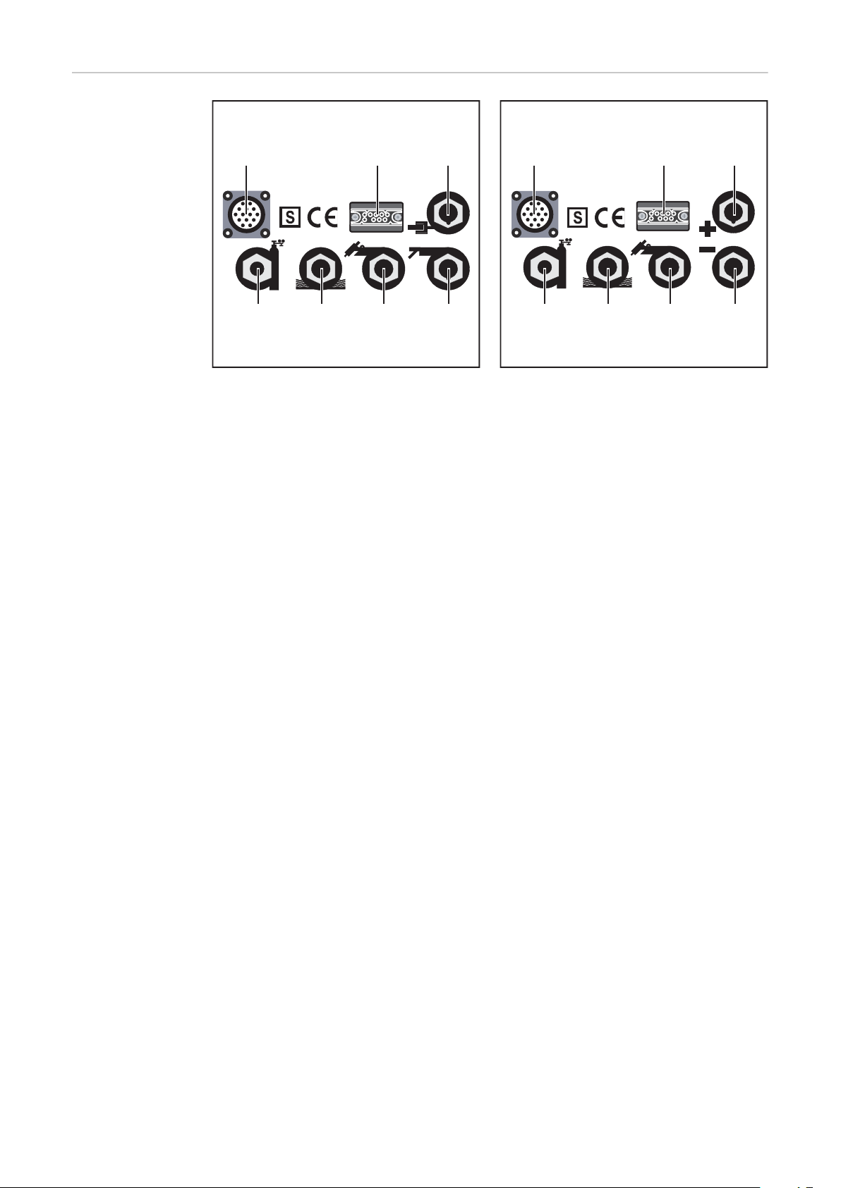
Connections, switches and system extensions
(1) (2) (3)
(4)(5)(6)(7)
(1) (2) (3)
(4)(5)(6)(7)
MagicWave /
TransTig connections with
Fronius welding
torch central connector F
EN-US
Fig.7 MagicWave connections on the front of the
device
(1) Remote control connection socket ... standardized connection socket for sys-
tem expansions
(2) Torch control connection socket ... for connecting the welding torch plug
socket
(3) MagicWave: Grounding cable connection socket ... for connecting the
grounding cable
TransTig: (+) - current socket with bayonet latch ... for connecting
- the grounding cable for TIG welding
- the electrode cable or grounding cable for manual metal arc welding
(depending on the type of electrode used)
(4) MagicWave: Welding torch connection socket ... for connecting the electrode
cable during manual metal arc welding
TransTig: (-) - current socket with bayonet latch ... for connecting
- the electrode cable or grounding cable for manual metal arc welding
(depending on the type of electrode used)
(5) Connection socket for TIG welding torch ... for connecting the TIG welding
torch
(6) Connection socket for water supply ... for connecting a water-cooled welding
torch
(7) Connection socket for water return ... for connecting a water-cooled welding
torch
Fig.8 TransTig connections on the front of the device
27
MagicWave /
(1)
(2)
(3)
(4)(5)(6)(7)
(1)
(4)
(5)
(6)(7)
(2)
(3)
TransTig connections with welding torch central
connector GWZ
Fig.7 MagicWave connections on the front of the
device
Fig.8 TransTig connections on the front of the device
(1) Remote control connection socket ... standardized connection socket for sys-
tem expansions
(2) Torch control connection socket ... for connecting the welding torch plug
socket
(3) MagicWave: Grounding cable connection socket ... for connecting the
grounding cable
TransTig: (+) - current socket with bayonet latch ... for connecting
- the grounding cable for TIG welding
- the electrode cable or grounding cable for manual metal arc welding
(depending on the type of electrode used)
(4) MagicWave: Welding torch connection socket ... for connecting the electrode
cable during manual metal arc welding
TransTig: (-) - current socket with bayonet latch ... for connecting
- the electrode cable or grounding cable for manual metal arc welding
(depending on the type of electrode used)
(5) Connection socket for TIG welding torch ... for connecting
- the TIG welding torch
- the water supply (water return) of a water-cooled TIG welding torch
(6) Connection socket for water supply ... for connecting a water-cooled welding
torch
(7) Shielding gas connection socket
28

MagicWave /
(1)
(2)
(3)
(4)
TransTig connections with welding torch central
connector GWZ
EN-US
Fig.7 MagicWave connections on the front of the
device
(1) Power switch ... for switching the power source on and off
(2) Shielding gas connection socket
(3) Gas-test button ... for setting the required quantity of shielding gas on the gas
pressure regulator. When the gas-test button is pressed, shielding gas flows out.
(4) Mains cable with strain relief
29

Before installation
Safety
Danger due to incorrect operation.
This can result in severe personal injury and damage to property.
▶
▶
Intended use The power source is only intended for TIG welding and MMA welding.
Any other use is deemed to be "not in accordance with the intended purpose." The manufacturer shall not be liable for any damage resulting from such improper use.
Intended use also means
- Following all the instructions in these Operating Instructions
- Carrying out all the specified inspection and maintenance work
Setup regulations The power source has been tested according to protection class IP 23. This means:
- Protection against penetration by solid foreign bodies larger than Ø 12.5 mm (.49
- Protection against spraywater at any angle up to 60° from the vertical
WARNING!
Do not use the functions until you have fully read and understood the Operating
Instructions
Read and understand all the Operating Instructions for the system components,
especially the safety rules, in full
in.)
WARNING!
Danger from devices falling or toppling over.
This can result in severe personal injury and damage to property.
Place devices on a solid, level surface so that they remain stable.
▶
The ventilation channel is a very important safety device. When selecting the setup location, ensure that the cooling air can enter or exit unhindered through the vents on the
front and back. Any electrically conductive dust (e.g. from grinding work) must not be
allowed to be sucked directly into the power source.
Mains operation Appliances are designed for the grid voltage stated on the rating plate. If the mains cable
or mains plug has not been attached to your version of the appliance, these must be
installed according to national standards. Fuse protection for the grid lead can be found
in the technical data.
WARNING!
Danger due to insufficiently dimensioned electrical installation.
This can result in severe personal injury and damage to property.
The mains lead and its fuse protection must be rated accordingly
▶
The technical data shown on the rating plate applies
▶
30

Generatorpowered operation
The power sources are compatible with any generator if the maximum specified apparent
power is at least:
- MW 2600 / TT 2600: 18 kVA
- MW 2600 CEL / TT 2600 CEL: 20 kVA
- MW 3000 / TT 3000: 22 kVA
NOTE!
The voltage delivered by the generator must never fall outside of the mains voltage tolerance range. The mains voltage tolerance is specified in the "Technical data" chapter.
EN-US
31

Commissioning
General
WARNING!
Danger of electric shock!
This can result in severe personal injury and damage to property.
Set the power switch to the "O" position
▶
Disconnect the device from the mains
▶
The commissioning of the power source is described as follows:
- for the main application TIG welding,
- based on a standard configuration for a TIG welding system.
The standard configuration consists of the following components:
- Power source
- Cooling unit
- TIG manual welding torch
- Gas pressure regulator
- Gas cylinder
- Gas cylinder holder
- Trolley
The following steps are intended to provide you with an overview of commissioning the
power source.
Notes on the
cooling unit
Connecting the
shielding gas cylinder
For detailed information on the individual steps, refer to the instructions for the corresponding devices.
A cooling unit is recommended for the following applications:
- Robot mode
- Hosepacks over 5 m in length
- TIG AC welding
- General welding in the higher power range
The cooling unit is supplied with power via the power source. When the mains switch of
the power source is switched to position "I", the cooling unit is ready for operation.
CAUTION!
Danger from falling gas cylinder.
This can result in personal injury and damage to property.
Use safety strap
▶
Secure the safety strap at the height of the upper part of a gas cylinder
▶
Never secure the safety strap to the neck of the cylinder
▶
32
Fix the shielding gas cylinder to the trolley
1

Connect the shielding gas cylinder:
2
- Remove the protective cap of the shielding gas cylinder
- Briefly turn the valve of the shielding gas cylinder to the left to remove surrounding dirt
- Check the seal on the gas pressure regulator
- Screw the gas pressure regulator onto the shielding gas cylinder and tighten it
When using a TIG welding torch with integrated gas connection:
Connect the gas pressure regulator to the shielding gas connection socket on the
1
rear of the power source using the gas hose
Tighten union nut
2
When using a TIG welding torch without integrated gas connection
Connect gas hose with gas pressure regulator
1
EN-US
Establish a connection with the
workpiece
Connect the
welding torch
Set the power switch to the "O" position
1
Insert the grounding cable into the positive current socket and lock
2
Connect the other end of the grounding cable to the workpiece
3
Set the power switch to the "O" position
1
Insert the welding power-lead of the TIG welding torch into the negative current
2
socket and twist it clockwise to lock
Connect the plug socket of the welding torch to the torch control connection socket
3
and lock it
Equip welding torch (see Operating Instructions for welding torch)
4
When using a TIG welding torch with integrated gas connection:
Connect the gas pressure regulator to the shielding gas connection socket on the
1
rear of the power source using the gas hose
Tighten union nut
2
Only when using a water-cooled welding torch:
connect the water connections of the welding torch to the water supply and water
1
return connections of the cooling unit.
33

TIG Operating Modes
General
Symbols and
explanations
WARNING!
Danger due to incorrect operation.
This can result in severe personal injury and damage to property.
Read these Operating Instructions
▶
All system component Operating Instructions, especially the safety rules
▶
Follow the guidelines referring to setting, setting range, and units of measurement for the
available welding parameters in the chapter "Program level preferences".
Pull back the torch trigger and hold it in this position
Release the torch trigger
Briefly pull the torch trigger back (<0.5 s)
Push the torch trigger forward and hold it in this pos-
ition
Explanation
GAS Gas pre-flow time
I
S
t
up
I
H
t
down
Starting-current phase:the temperature is raised gently at low welding current,
so that the filler metal can be positioned correctly
UpSlope phase: the starting current is continually increased up to the welding
current
Welding current phase:even heat input into the parent material whose temperature is raised by the advancing heat
DownSlope phase: steady lowering of the welding current until it reaches the
final current.
Briefly push the torch trigger forwards (<0.5 s)
Release the torch trigger
34
I
E
Crater-fill phase:to avoid local overheating of the parent material caused by
heat accumulation at the end of welding. This prevents possible sagging of the
weld seam.

SPt Spot welding time
I
t
I
H
G-HGAS t
up
t
down
G-L
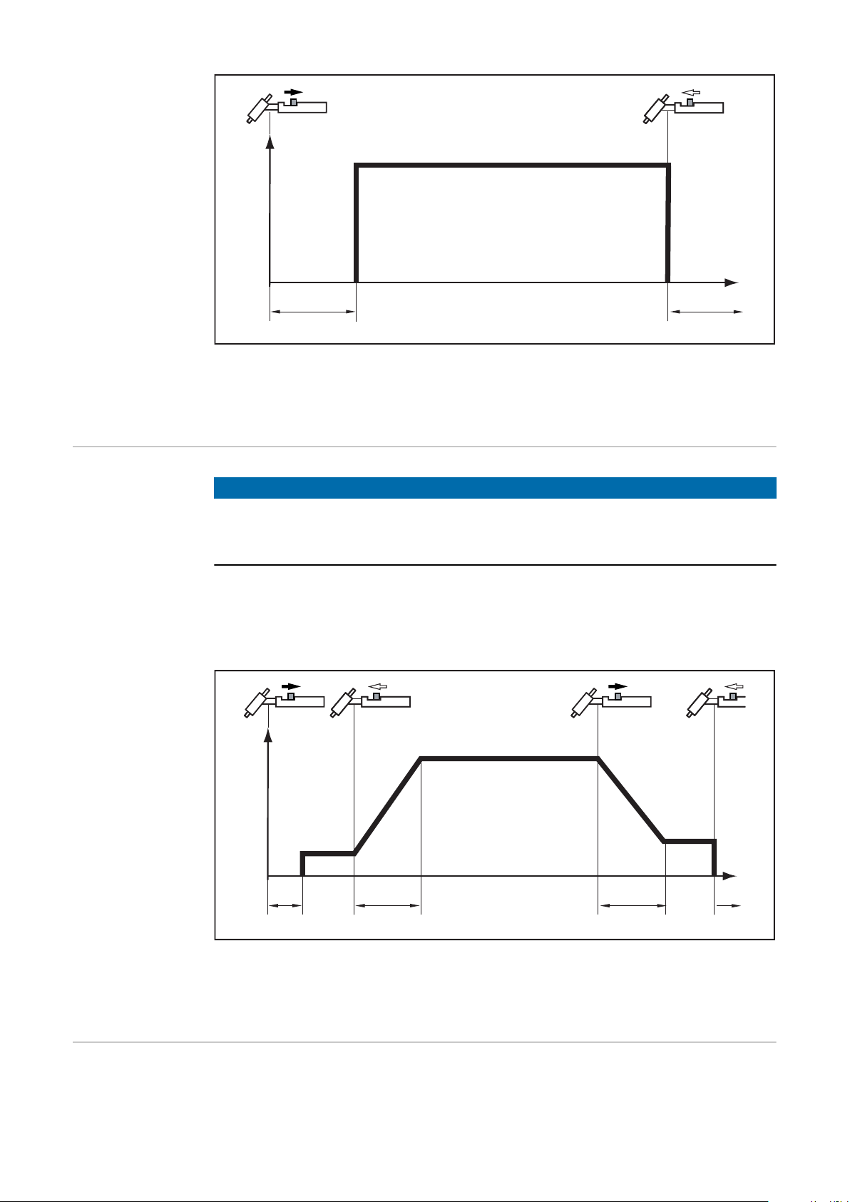
2-step
G-... G-H / G-L: Gas post-flow time
EN-US
NOTE!
The welding parameter StS must be set to "OFF" (section Available TIG paramet-
ers). With the power source in its delivery condition, the welding parameter StS is
set to "OFF".
- Welding: Pull back the torch trigger and hold it in this position
- End of welding: Release the torch trigger
Special 2-step
2-step mode
The explanation of the symbols and abbreviations can be found in the section Symbols
and explanations.
NOTE!
The welding parameter StS must be set to "ON" (section "Program level prefer-
ences”). With the power source in its delivery condition, the welding parameter
StS is set to "OFF".
- Welding: Pull back the torch trigger and hold it in this position
- End of welding: Release the torch trigger
35
I
t
I
H
G-L
GAS
G-H
Special 2-step mode
I
t
I
1
GAS
I
S
t
up
t
down
I
E
G-L
G-H
The explanation of the symbols and abbreviations can be found in the section Symbols
and explanations.
4-step
NOTE!
The welding parameter SFS must be set to "OFF" (section "Program level prefer-
ences”). With the power source in its delivery condition, the welding parameter
SFS is set to "OFF".
- Start of welding with starting current IS: Pull back the torch trigger and hold it in this
position
- Welding with main current IH: Release the torch trigger
- Lowering to final current IE: Pull back the torch trigger and hold it in this position
- End of welding: Release the torch trigger
4-step with intermediate lowering
36
4-step mode
The explanation of the symbols and abbreviations can be found in the section Symbols
and explanations.
In the variant of 4-step mode shown below, an intermediate lowering to IE of the welding
current takes place by pressing and holding the torch trigger.
- Select 4-step mode

NOTE!
I
t
I
1
GAS
I
S
t
up
t
down
I
E
G-L
G-H
I
t
I
H
GAS
I
S
t
down
I
E
G-L
I
H
I
3
t
up
G-H
The welding parameter SFS must be set to "OFF" (section "Program level prefer-
ences”). With the power source in its delivery condition, the welding parameter
SFS is set to "OFF".
- Intermediate lowering to the set lowering current IE during the main current phase:
Push the torch trigger forward and hold it in this position
- Resume main current: Release the torch trigger
EN-US
Special 4-step:
Version 1
4-step with intermediate lowering mode
The explanation of the symbols and abbreviations can be found in the section Symbols
and explanations.
The variant of the special 4-step mode shown below enables the intermediate lowering
to the set lowering current I3 by means of TIG torches without double-button function by
briefly pressing the torch trigger. Briefly pull back the torch trigger again to return to the
main current IH.
- Select 4-step mode
- Set the setup parameter SFS to "1"
(section "Program level preferences”)
Special 4-step mode: Version 1
The explanation of the symbols and abbreviations can be found in the section Symbols
and explanations.
37

Special 4-step:
I
t
I
H
GAS
I
S
t
down
I
E
G-L
I
H
I
E
t
up
t
down
t
up
G-H
I
t
I
H
GAS
I
S
t
down
I
E
G-L
I
H
I
E
t
up
t
down
t
up
G-H
I
t
I
H
GAS
I
S
G-L
I
H
I
E
t
up
t
down
t
up
G-L
Version 2-4
The variants of the special 4-step mode shown below enable the intermediate lowering
to the set lowering current by means of TIG torches with double-button function.
- Select 4-step mode
- Set the setup parameter SFS to "2, 3, 4 or 5" for the desired variant (section "Pro-
gram level preferences”)
Special 4-step mode: Version 2
38
Special 4-step mode: Version 3
Special 4-step mode: Version 4

The explanation of the symbols and abbreviations can be found in the section Symbols
I
t
I
H
GAS
I
S
I
E
G-L
t
up
t
down
IH >
IH <
G-H
and explanations.
EN-US
Special 4-step:
Version 5
The following variant of the special 4-step mode allows an increase and decrease of the
welding current without welding torch Up / Down.
The longer the torch trigger is pressed during welding, the further the welding current
increases (up to the maximum).
After releasing the torch trigger, the welding current remains constant. The longer the
torch trigger is pressed forward again, the further the welding current is reduced.
Special 4-step mode: Version 5
The explanation of the symbols and abbreviations can be found in the section Symbols
and explanations.
39

TIG welding
Safety
Preparation
WARNING!
Danger due to incorrect operation.
Operating the equipment incorrectly can cause serious injury and damage.
Do not use the functions described here until you have fully read and understood the
▶
following documents:
These Operating Instructions
▶
All system component Operating Instructions, especially the safety rules
▶
WARNING!
Danger of electric shock.
An electric shock can be fatal. If the unit is connected to the grid during installation, there
is a danger of serious injury and damage to property.
Only carry out work on the device if the power switch is in the "O" position
▶
Only carry out work on the device when it has been disconnected from the grid.
▶
Unplug the mains plug
1
Set the power switch to the "O" position
2
Insert the grounding cable into the positive current socket and lock
3
Connect the other end of the grounding cable to the workpiece
4
Insert the welding power-lead of the TIG welding torch into the negative current
5
socket and twist it clockwise to lock
Connect the control plug of the welding torch to the torch control connection and lock
6
it
Equip welding torch (see Operating Instructions for welding torch)
7
Screw the gas pressure regulator onto the shielding gas cylinder and tighten it
8
40
When using a TIG welding torch with integrated gas connection:
Connect the gas pressure regulator to the shielding gas connection socket on the
1
rear of the power source using the gas hose
Tighten union nut
2
Only when using water-cooled welding torch and cooling unit:
connect the water connections of the welding torch to the water supply and water
1
return connections of the cooling unit.
Insert the mains plug
2
Only if a remote control is used:
Connect the remote control to the remote control connection socket
1

Select operating
(1)
(2)
(3)
(1+4)
(3)
(2+4)
mode
WARNING!
Danger of electric shock.
This can result in severe personal injury and damage to property.
When the power switch is switched to position "I", the tungsten electrode of the
▶
welding torch is live. Ensure that the tungsten electrode is not touching any people
or electrically conductive or grounded parts (housing, etc.)
EN-US
Select the operating mode using the key (3):
- Operating mode 2-step mode (1) with HF ignition
- Operating mode 4-step mode (2) with HF ignition
- Operating mode 2-step mode (1+4) with contact ignition
- Operating mode 4-step mode (2+4) with contact ignition
NOTE!
Do not use pure tungsten electrodes for TransTig power sources (color code:
green).
Select process Select the process using the key:
AC welding process
DC welding process
41

Cap-shaping
(A) (B)
(MagicWave)
When the AC welding process is selected, automatic cap-shaping is available for the
MagicWave power sources. For optimum results, this takes into account the set electrode diameter.
The automatic cap-shaping ensures the
formation of the optimum cap during the
welding start. Separate cap-shaping on a
test workpiece is not necessary.
Cap-shaping
NOTE!
Welding parameter setting
Adjust the shielding gas quantity
Ignition of the arc
- general
The AC welding process with activated cap-shaping is not necessary if a sufficiently large cap is formed on the tungsten electrode.
Set the electrode diameter on the tungsten electrode adjuster. Activate cap-shaping by
briefly pressing the welding torch trigger forward.
Use the potentiometers on the control panel to set the desired welding parameters.
A list of the welding parameters available in the program levels can be found in the section "Program level preferences”.
Press the gas-test button
1
Set desired gas quantity
2
For an optimal ignition sequence, when TIG AC welding is selected, the MagicWave
power sources take into account the electrode diameter. In addition, the current electrode temperature is also calculated on the basis of the previous welding time and welding pause.
TIG synchronous
welding AC
(MagicWave)
42
Used for mains synchronization of two power sources, for simultaneous AC welding on
both sides.
NOTE!
The phase sequence must be the same for both devices.

For information on setting the SYn parameter, refer to chapter "Program levels P1-P3",
section "Program level AC parameter P3".
HF ignition For information on setting the setup parameter HFt, refer to the section "Program level
preferences”.
Use welding parameter HFt to set the time interval of the HF pulses to 0.01 s. When the
power source is delivered, the welding parameter HFt is set to "0.01s".
NOTE!
If problems occur with sensitive devices in the immediate vicinity, increase the
welding parameter HFt to up to 0.4 s.
Unlike with contact ignition, there is no risk of contaminating the electrode and workpiece
during HF ignition.
Proceed as follows to ignite the arc:
Position the gas nozzle at the ignition
1
point so that there is a distance of
approximately 2 to 3 mm (0.08 to 0.12
in.) between the tungsten electrode
and the workpiece. Distance exists.
EN-US
Apply the gas nozzle
Touchless HF ignition
Increase the tilt angle of the welding
1
torch and press the torch trigger
according to the selected operating
mode (section TIG Operating Modes)
Arc ignites without touching the work-
2
piece
43

Welding
Contact ignition Proceed as follows to ignite the arc:
Tilt the welding torch to the normal
1
position
Position at the ignition point so that
1
there is a distance of approximately 2
to 3 mm (0.08 to 0.12 in.) between the
tungsten electrode and the workpiece.
Distance exists
Apply the gas nozzle
Ignition through workpiece contact
Press torch trigger - shielding gas
1
flows
Gradually tilt the welding torch up until
2
the tungsten electrode touches the
workpiece
44

Welding
Raise the welding torch and tilt it into
1
the normal position, the arc ignites
EN-US
Ignition monitoring
If no arc emerges within 5 seconds, the power source automatically switches off.
Repeated pressing of the torch trigger is required for a new attempt.
45

Manual Metal Arc Welding
Safety
Preparation
WARNING!
Danger due to incorrect operation.
This can result in severe personal injury and damage to property.
Do not use the functions described here until you have fully read and understood the
▶
Operating Instructions.
Do not use the functions described here until you have fully read and understood all
▶
of the Operating Instructions of the system components, especially the safety rules.
Switch off existing cooling units (see section "Program level preferences”Available
TIG parameters)
WARNING!
Danger of electric shock.
An electric shock can be fatal. If the unit is connected to the grid during installation, there
is a danger of serious injury and damage to property.
Only carry out work on the device if the power switch is in the "O" position
▶
Only carry out work on the device when it has been disconnected from the grid.
▶
Unplug the mains plug
1
Set the power switch to the "O" position
2
Remove TIG welding torch
3
NOTE!
The TransTig power source does not have a switchover between the processes
MMA DC- welding / MMA DC + welding.
If the TransTig power source is to be changed from MMA DC- welding to MMA DC +
welding, swap the electrode holder and grounding cable at the welding sockets.
Insert the grounding cable into the positive current socket and lock
1
Connect the other end of the grounding cable to the workpiece
2
Insert the welding power-lead into the negative current socket and twist it clockwise
3
to lock
Insert the mains plug
4
Only if a remote control is used:
Connect the remote control to the remote control connection socket
1
46

Select operating
(3) (5)
mode
WARNING!
Danger of electric shock.
This can result in severe personal injury and damage to property.
When the power switch is switched to position "I", the tungsten electrode of the
▶
welding torch is live. Ensure that the tungsten electrode is not touching any people
or electrically conductive or grounded parts (housing, etc.).
- Switch the power switch to the "I" position
Select the operating mode using the key
(3):
- Manual metal arc welding operating
mode (5)
EN-US
Select process
(MagicWave)
- Select the process using the key:
AC welding process or
DC- welding process
DC+ welding process
Welding parameter setting
A list of the available welding parameters can be found in the section "Program level
preferences”.
47

- Welding voltage display shows open circuit voltage
- Connect remote control TPmc if necessary (set dynamic and HotStart)
- Preselect welding current IH
- Initiate welding process.
48

Remote control
(1)
(2)
(3)
EN-US
Safety
Danger due to incorrect operation.
This can result in severe personal injury and damage to property.
▶
▶
Danger of electric shock!
This can result in severe personal injury and damage to property.
▶
▶
General A remote control is useful as soon as you want to make adjustments directly from the
welding station. Special remote control cables in lengths of 5 or 10 m (197 or 394 in.)
connect the remote control to the power source.
The following remote control types are available:
- TIG and MMA remote control (AC) TR53mc
- MMA and TIG remote control (DC) TPmc
- TIG pulse remote control (AC/DC) TR50mc
- TIG spot welding remote control (DC) TR51mc
- TIG foot controller (AC/DC) TR52mc
WARNING!
Read and understand these Operating Instructions
Read and understand all the Operating Instructions for the system components,
especially the safety rules
WARNING!
Only carry out work on the device if the power switch is in the "O" position,
and the device has been disconnected from the grid.
AC remote control TR 53mc
The AC remote control TR 53mc is especially suitable for TIG AC welding operation.
The following welding parameters can be set via the remote control:
- Main welding current IH
- AC balance
- AC frequency
AC remote control TR53 mc
49

(1) Main current IH adjuster ... for stepless adjustment of the welding current
(1)
(1)
(2)
(3)
(5)
(6) (7)
(4)
(2) AC arc frequency adjuster ... for changing the arc concentration
(3) Balance adjuster ... for changing the positive and negative half-wave in the
MMA and TIG AC range.
Important! When using the remote control for manual metal arc welding in the AC or DC
range, the values set in the device apply for the HotStart current, HotStart time and
dynamics. (Chapter "Program level preferences")
TIG pulse remote
control TR 50mc
Connect the TIG pulse remote control to the LocalNet connection socket.
- TIG pulse welding indicator (1) flashes as soon as the remote control is connected.
Two operating modes are possible with the TR 50mc pulse remote control:
- Pulse current regulation I1 on remote control TR 50mc
- Pulse current regulation I1 with foot remote control TR 52mc
50
TIG pulse remote control TR 50mc
(1) Adjuster for pulse current I1... for stepless adjustment of the pulse main current
(2) Adjuster for pulse frequency f ... for stepless adjustment of the pulse fre-
quency depending on the preselected frequency range (5)
(3) Adjuster for base current I2... for percentage adjustment of the base current
from the set value of the pulse current I1 (1)
(4) Adjuster for duty cycle dcY ... for percentage adjustment of the ratio between
the pulse current phase and the base current phase.
Setting example for low heat input:
Duty cycle adjuster in position "10"
- Short pulsing current phase of 10%
- Long base current phase of 90%
(5) Adjuster for frequency range ... for step-by-step pre-selection of the desired
frequency
Setting ranges:

- 0.2–2 Hz
)3
GF<
,
,
W
W
XS
W
GRZQ
,
6
,
(
,
- 2–20 Hz
- 20–200 Hz
- 200–2000 Hz
The illustration below shows TIG pulsing with the DC welding process selected.
TIG pulsing - welding current progression curve
EN-US
TIG foot remote
control TR 52mc
- IS ........... Starting current
- IE ........... Final current
- tUp ........ UpSlope
- tDown ... DownSlope
- F-P ........ Pulse frequency
(1/F-P = time between two pulses)
- dcY........ Duty cycle
- I2 .......... Base current
- I1 .......... Main current
(6) Power source connection socket ... for connecting the remote control to the
power source
(7) Foot remote control connection socket ... for connecting the foot remote con-
trol TR 52mc. Particularly advantageous for manual TIG welding. The pulse
welding current can be changed during the welding process (e.g. variable material thickness).
The TIG foot remote control TR 52mc is especially suitable for welding complicated
workpiece shapes.
51

TIG foot remote control TR 52mc
I
t
I
H
G-H
GAS
I
I
G-L
Function:
- 2-step mode indicator lights up as soon as the remote control is connected (automatic switching)
- Set main current adjuster IH to desired maximum current
- Set gas pre-flow time and gas post-flow time directly at the power source (section
"Program level preferences”)
- Initiate ignition process by lightly stepping on the pedal
- Starting current IS, main current IH and final current can be controlled with the foot
pedal
Important! Welding current does not exceed the preselected value when the pedal is
depressed.
- Switch off welding current by completely depressing the pedal
- The welding process is interrupted, the gas post-flow time expires
TIG spot welding
remote control
TR 51mc
52
Functional sequence with remote foot control TR 52mc
Welding of stainless constructions in the thin sheet area is often not possible due to
severe material distortion. Likewise, joints that are only accessible from one side can be
easily mastered using the TIG spot process.
Important! Aluminum materials cannot usually be joined by TIG spot welding, or if so
then only poorly. The oxide skin between the sheets cannot be removed.

(3)
(1)
(2)
(1) Controller for spot welding current
I
t
I
1
GAS
t
up
t
down
SPt
G-L
G-H
I
1
(2) Remote control connection socket
(3) Spot welding time controller SPt
(0.1 - 8 s)
TIG spot welding remote control TR 51mc
Functional sequence:
- 2-step mode indicator lights up as soon as the remote control is connected (automatic switching)
- Set current lowering time on the power source
- Use special spot welding nozzle (sits insulated on the cone)
- Mount tungsten electrode set back from nozzle edge (approx. 2-3 mm (0.10 in.)
depending on spot size)
- Place welding torch on the sheet and apply slight pressure to the parent material
- Initiate spot welding process (avoid air gap)
EN-US
Remote control
TP MC / TP MCCEL
Spot welding
The TP MC / TP MC-Cel remote control is particularly suitable for MMA and TIG DC
welding.
53

(1)
(2)
(3)
Remote control TP mc
(2)
(1)
(3)(4)
(5)
Remote control TP mc-CEL
(1) Welding current adjuster ... for stepless adjustment of the welding current
(2) Dynamic adjuster ... dYn - dynamic - dynamic correction
To obtain the best possible welding results, the arc-force dynamic will sometimes
need to be adjusted. For the setting of the "dYn" welding parameter, see the section Select and change setup parameters.
Operating principle
At the moment of droplet transfer or in event of a short circuit, a short-term
increase in the amperage will occur. To maintain a stable arc, the welding current
temporarily rises. If the rod electrode is at risk of sinking into the weld pool, this
action prevents the weld pool from solidifying, as well as reducing the duration of
the arc's short circuit. The risk of the rod electrode sticking is therefore largely
ruled out.
Setting range of welding parameter dYn
0 ......... soft and low-spatter arc
10 ....... harder and more stable arc
(3) HotStart adjuster ... To obtain the best possible welding result, the HotStart
function will sometimes need to be adjusted.
Advantages
- Improved ignition properties, even when using electrodes with poor ignition
properties
- Better fusion of the parent material during the start-up phase, meaning fewer
cold-shut defects
- Slag inclusions largely avoided
54
Refer to the section "Program level preferences” for the setting of the available welding parameters.

I (A)
t (s)
0,5 1 1,5
Hti
I
1
HCU
100
150
Key
(24)
- HTI .... Hot current time = 0-2 s, fact-
ory setting 0.5 s
- HCU .. HotStart current = 0-100%
- I1 ........ Main current = set welding
current
Function
During the specified hot-current time (Hti),
the welding current is increased to a certain value. This value is 0-100% (HCU)
higher than the set welding current (I1).
Remote control - HotStart function
(4) Pole selector switch ... for switching the electrode polarity
Important! The MMA cable must be connected to the connection socket (24).
EN-US
(5) Range switch for TIG or electrode
55

Working with program levels
(1)
(2)
(3)
(4)
(5)
Overview The following figure shows an overview of the welding parameter settings in the program
level preferences, using the MagicWave control panel as an example. A detailed description of these settings can be found in the following chapters.
1. Setup parameters for rod electrode:
Hti ...... Hot current time
HCU ... HotStart current
dYn .... Dynamic correction
PRO ... Save program
FAC ... Reset welding system
2. Mode button
3. Process button
4. TIG welding parameters:
GAS... Gas pre-flow
G-L .... Gas post-flow at minimum welding current
G-H.... Gas post-flow at maximum welding current
UPS... UpSlope
SCU... Starting current in % of IH
I3 ....... Lowering current
HFt .... High frequency
SCU... Starting current rel/abs
StS..... Special 2-step mode
SFS ... Special 4-step mode
C-C.... Cooling unit control
E-S .... Power source shutdown
PRO ... Save program
FAC ... reset
5. TIG AC:
like operating mode TIG DC
56

"Program level preferences”
EN-US
Access
Select and
change setup
parameters
Available TIG
parameters
Select the desired operating mode TIG/Electrode
1
Switch off power source
2
Switch on the power source while holding down the operating mode (3) or process
3
(4) button.
Release mode (3) or process (4) button
4
Select the desired parameter using the operating mode (3) or process (18) button
1
Change the parameter value using the torch trigger
2
NOTE!
If problems occur with sensitive devices in the immediate vicinity, increase the welding
parameter HFt to up to 0.4 s.
GAS Gas pre-flow
Unit: Seconds
Setting range: 0 - 20
Factory setting: 0.4
G - L Gas-Low
Gas post-flow at minimum welding current (minimum gas post-flow time)
Unit: Seconds
Setting range: 2 - 26
Factory setting: 5
G - H Gas-High
Gas post-flow time at maximum welding current
Unit: Seconds
Setting range: 2 - 26
Factory setting: 15
The setting value for G-H only applies if the maximum welding current is actually
set. The actual value results from the momentary welding current. At medium
welding current, for example, the actual value is half the set value for G-H.
UPS UpSlope
Time for transition from starting current IS to welding current I
Unit: %
Setting range: DC: 0 - 100 / AC: 30 - 100 of the main current I
Factory setting: DC: 29 / AC: 50
SCU Start-Current
Starting current
Unit: Seconds
Setting range: 0 - 20
Factory setting: 0.4
H
H
57

I3 Lowering current
Unit: %
Setting range: 0 - 100 of the main current I
Factory setting: 50
HFt High Frequency time
High frequency ignition: Time interval of the HF pulses
Unit: Seconds
Setting range: 0.01 - 0.4
Factory setting: 0.01
SCU Start-Current
Starting current
Unit: Setting range: rel / abs
Factory setting: rel
StS Special two-step
Special 2-step mode
Unit: Setting range: ON / OFF
Factory setting: OFF
H
SFS Special four-step
Special 4-step mode
Unit: Setting range: OFF / 1 - 5
Factory setting: OFF
The variants of the special 4-step mode are described in the chapter "Operating
modes".
C - C Cooling unit control
Cooling unit control (optional)
Unit: Setting range: Aut / ON / OFF
Factory setting: Aut
"Aut" setting ....... Switches off the cooling unit 2 minutes after the end of welding
"ON" setting ......Cooling unit is always switched on
"OFF" setting ......Cooling unit remains permanently switched off
E - S Emergency Stop
to stop the power source via the robot
Unit: Setting range: ON / OFF
Factory setting: OFF
58
PRO Program
save the set parameters by pressing the torch trigger
FAC Factory
Reset the welding system by pressing the torch trigger
Available parameters when MMA welding mode is selected:
Hti Hot-current time
Hot current time

Unit: Seconds
I (A)
t (s)
0,5 1 1,5
Hti
I
1
HCU
100
150
Setting range: 0.2 - 2.0
Factory setting: 0.5
HCU Hot-start current
HotStart current
Unit: %
Setting range: 0 - 100
Factory setting: 50
To obtain the best possible welding result, the HotStart function will sometimes
need to be adjusted.
Advantages:
- Improved ignition properties, even when using electrodes with poor ignition
properties
- Better fusion of the parent material during the start-up phase, meaning fewer
cold-shut defects
- Slag inclusions largely avoided
EN-US
Example of "HotStart" function
Key
Hti .... Hot current time = 0-2 s, factory setting 0.5 s
HCU .. HotStart current = 0-100%, factory setting 50%
I1 ........ Main current = set welding current
Function
During the specified hot-current time (Hti), the welding current is increased to a certain
value. This value is 0-100% (HCU) higher than the set welding current (I1).
dyn dYn - dynamic
Unit: A
Adjustment range: 0 - 200
Factory setting: 40
To obtain the best possible welding results, the arc-force dynamic will sometimes
need to be adjusted.
Operating principle
At the moment of droplet transfer or in event of a short circuit, a short-term
increase in the amperage will occur. To maintain a stable arc, the welding current
temporarily rises. If the rod electrode is at risk of sinking into the weld pool, this
action prevents the weld pool from solidifying, as well as reducing the duration of
59

the arc's short circuit. The risk of the rod electrode sticking is therefore largely
ruled out.
Setting range of the parameter dYn
0 ........ soft and low-spatter arc
100 .... harder and more stable arc
PRO Program
save the set parameters by pressing the torch trigger
FAC Factory
Reset the welding system by pressing the torch trigger
60

Program levels P1 - P3
EN-US
Access
Select and
change setup
parameters
Program level
service menu P1
Program level
code lock P2
Switch on the power source while holding down the operating mode (3) or process
1
(18) button. The display shows "---" for level preferences.
Press the torch trigger until
2
- --- appears .... "Program level preferences”
- P1 appears ... Program level service menu
- P2 appears ... Program level code lock
- P3 appears ... Program level AC parameters
Release mode (3) or process (18) button
3
Select the desired parameter using the operating mode (3) or process (18) button
1
Change the parameter value using the torch trigger
2
Service menu with various test programs
When the power source is delivered, the code lock is deactivated.
It is possible to enter a three-digit code.
Factory setting 321
NOTE!
If the code is entered incorrectly three times (ERR), the power source automatically switches to "LOC". The procedure must be repeated by switching off and on
again.
Important! Changes to the number combination must be noted in writing.
Select program level P2
1
Enter current code (for new devices 321)
2
- Set digit with main current controller IH (14)
- Confirm digit with operating mode button (3)
- Repeat the procedure twice until "Cod OFF" appears on the display.
Switch to "Cod ON" with torch trigger
3
CYC ... Cycle indicates how often the device can be switched on without having to
4
enter a code.
Set the number of cycles with the torch trigger and confirm with the operating mode
5
key (3)
Enter new numerical code:
Select 0-9 / A-H by means of the torch trigger
1
Press the operating mode key (3) to confirm the entry
2
Repeat procedure twice until code is entered
3
Press the torch trigger
4
61

Enter new code again to check
5
The code is automatically stored after the third acknowledgment
6
Power source is ready for welding
7
Deactivate code:
Enter program level P2
1
Enter current code
2
- Set the IH digit with the adjuster
- Confirm digit with operating mode button (3)
- Repeat the procedure twice until "Cod ON" appears on the display
Press torch trigger "Cod OFF" appears
3
Change to "PRO" with the operating mode (3) or process (18) button.
4
Press the torch trigger
5
The current code is disabled and the power source is ready to weld
6
Important! The code from now on is 321 again.
When starting up the power source with the code lock activated, select digits using the
IH adjuster and confirm with the operating mode button (3).
Program level AC
parameters P3
(MagicWave)
Select parameters with the mode (3) or process (18) key and change their value with the
torch trigger.
Available parameters:
ACF AC frequency
Unit: Hz
Adjustment range: 40 - 100
Factory setting: 60
POS Positive
half-wave
Unit: Setting range: tri / SIN / rEC / OFF * (only for TIG)
Factory setting: SIN
nEG Negative
half-wave
Unit: Setting range: tri / SIN / rEC / OFF * (only for TIG)
Factory setting: 60
62
PRO Program
save the set parameters by pressing the torch trigger
SYn Synchronous function
Unit: Setting range: ON / OFF
Factory setting: OFF
* tri (triangle), SIN (sine), rEC (rectangle)

Fault diagnosis and correction
EN-US
Safety
WARNING!
Danger of electric shock.
This can result in severe personal injury and damage to property.
Before carrying out maintenance work on the device, carry out the following meas-
▶
ures
Set the power switch to - O -
▶
Unplug the device from grid power
▶
Attach a clear warning sign advising others not to switch the power source back on
▶
Use a suitable measuring instrument to ensure that electrically charged components
▶
(e.g., capacitors) are discharged
WARNING!
Danger due to insufficient ground conductor connection!
This can result in severe personal injury and damage to property.
The housing screws provide an adequate ground conductor connection for ground-
▶
ing the housing and should not be replaced under any circumstances by other
screws that do not provide a reliable ground conductor connection.
Displayed service
codes
If an error message appears on the screen that is listed here, the error can only be corrected by service personnel. Please note the displayed error message, as well as the
serial number and configuration of the power source, and contact the After-Sales Service
team with a detailed description of the error.
Error message from PC board UTI1A:
Err 102
Cause: Temperature sensor short circuit
Err 103
Cause: Temperature sensor interruption
Err 107
Cause: RAM access error
Err 109
Cause: Sec. overvoltage error
Err 110
Cause: Power source shutdown
Err 112
Cause: ADC offset error
Err 113
Cause: ADC gain error
Err 116
Cause: Cooling unit error
Err 117
Cause: Primary overcurrent error
63

Err 118
Cause: Supply voltage error (+5V, +15V)
Err 119
Cause: Serial transmission error
Err 120
Cause: Power module error
Err U-P
Cause: Primary overvoltage or undervoltage
Err 113
Cause: ADC gain error
Error message from PC board UTMS1
Err 004
Cause: Timer error (82C54)
Err 006
Cause: Itarget compensation error
Err 007
Cause: RAM access error
Err 008
Cause: SEEPROM access error
Power Source
Err 010
Cause: External error (only for robot operation)
Err 012
Cause: ADC offset error
Err 013
Cause: ADC gain error
Err 019
Cause: Serial transmission error
Err 021
Cause: Stack overflow
Power source not working
Power source switched on, displays do not illuminate
Cause:
Remedy:
Cause:
Remedy:
Grid lead damaged or broken, grid plug not inserted
Check grid lead, if necessary insert grid plug
Grid socket or grid plug faulty
Replace faulty parts
64
Cause:
Remedy:
Grid fuse
Replace grid fuse

No welding current
Power switch ON, overtemperature indicator illuminates
Cause:
Remedy:
Overloading
Observe the duty cycle
EN-US
Cause:
Remedy:
Cause:
Remedy:
No welding current
Power source switched on; displays and indicators light up
Cause:
Remedy:
Cause:
Remedy:
No function after pressing torch trigger
Power source power switch is ON and indicators are lit up
Cause:
Remedy:
Thermal automatic circuit breaker has tripped
Wait until the power source automatically comes back on after the end of
the cooling phase
Fan in the power source is faulty
Contact After-Sales Service
Incorrect ground connection
Check ground connection and terminal for polarity
Power cable in welding torch damaged or broken.
Replace the welding torch
Only for welding torches with an external control plug: Control plug not
plugged in
Plug in control plug
Cause:
Remedy:
Cause:
Remedy:
No shielding gas
All other functions are OK
Cause:
Remedy:
Cause:
Remedy:
Cause:
Remedy:
Cause:
Remedy:
Cause:
Remedy:
Power on remaining time after switching on not yet expired
Wait 10 s after switching on
Welding torch or welding torch control line faulty
Replace the welding torch
Gas cylinder empty
Change gas cylinder
Gas pressure regulator faulty
Replace the gas pressure regulator
Gas hose is not fitted or is damaged
Fit or change gas hose
Welding torch faulty
Change welding torch
Gas solenoid valve faulty
Contact After-Sales Service
65

Poor-quality weld properties
Cause:
Remedy:
Incorrect welding parameters
Check settings
Cause:
Remedy:
Welding torch gets very hot
Cause:
Remedy:
Cause:
Remedy:
Cause:
Remedy:
Incorrect ground connection
Check ground connection and terminal for polarity
Welding torch is inadequately sized
Observe duty cycle and load limits
For water-cooled systems only: Coolant flow too low
Check water level, water flow rate, water contamination, etc. Coolant pump
blocked: Switch on the shaft of the coolant pump at the gland using a
screwdriver
For water-cooled systems only: C-C parameter is set to "OFF".
In the Setup menu, set the "C-C" parameter to "Aut" or "ON".
66

Service, maintenance and disposal
General The power source only requires minimal care and maintenance under normal operating
conditions. However, some important points must be noted to ensure that the welding
system remains in a usable condition for many years.
WARNING!
Danger of electric shock.
This can result in severe personal injury and damage to property.
Set the power switch to the "O" position
▶
Unplug the device from grid power
▶
Attach a clear warning sign advising others not to switch the power source back on
▶
Use a suitable measuring instrument to ensure that electrically charged components
▶
(e.g., capacitors) are discharged
At every start-up - Check mains plug and mains cable, as well as the welding torch, interconnecting
hosepack, and ground earth connection for damage
- Check if the all-round clearance of the device is 0.5 m (1 ft. 7 in.) so that cooling air
can circulate unimpeded
EN-US
NOTE!
Air intake and exhaust openings must also not be blocked or even partially
covered.
Every 2 months - If present: clean air filter
Every 6 months - Dismantle device side panels and blow the inside of the device clean with dry,
reduced compressed air
NOTE!
Risk of damage to electronic parts. Do not bring the air nozzle too close to electronic parts.
- Also clean the cooling air ducts if there is a large accumulation of dust
Disposal Materials should be disposed of according to valid local and national regulations.
Spare parts - MagicWave 2600
- MagicWave 3000
- TransTig 2600
- TransTig 3000
67

Technical data
Special voltage
MagicWave
2600/2600CEL
WARNING!
Danger due to insufficiently dimensioned electrical installations.
Serious damage to property possible.
The mains lead and its fuse protection must be rated accordingly.
▶
The technical data shown on the rating plate applies.
▶
MW 2600 MW 2600CEL
Grid voltage 3x400 V 3x400 V
Mains voltage tolerance -20% / +15% -20% / +15%
Mains fuse, slow-blow 16 A 16 A
Apparent power at
40% ED
50% ED
60% ED
100% ED
Cos phi1
150 A
260 A
-
11.1 kVA
10.6 kVA
8.1 kVA
0.99
0.99
15.7 kVA
-
10.4kVA
8.1 kVA
0.99
0.99
Efficiency 86% 83%
Welding current range
DC
AC
Welding current at 10 min/40°C
40% ED
50% ED
60% ED
100% ED
Open circuit voltage 56 V DC 75 V DC
max. working voltage 40 V 48 V
Striking voltage (Up).
The arc ignition device is suitable for
manual operation.
Protection class IP 23 IP 23
Type of cooling AF AF
Insulation class F F
Dimensions l/w/h 625/290/480 mm
Weight (without cooling unit) 33 kg
3 - 260 A
5 - 260 A
260 A
240 A
185 A
9.5 kV 9.5 kV
24.61/11.42/18.90 in.
72.75 lb.
3 - 260 A
5 - 260 A
260 A
180 A
145 A
625/290/480 mm
24.61/11.42/18.90 in.
30 kg
66.14 lb.
68
Mark of conformity CE, CSA CE, CSA
Safety signs S S

MagicWave 3000
MW 3000 MW 3000
Grid voltage 3x230 V 3x400 V
Mains voltage tolerance -20% / +15% -20% / +15%
Mains fuse, slow-blow 20 A 16 A
Apparent power at
40% ED
50% ED
60% ED
100% ED
Cos phi1
150 A
260 A
Efficiency 83% 85%
Welding current range
DC
AC
Welding current at 10 min/40°C
40% ED
50% ED
60% ED
100% ED
9.7kVA
6.1 kVA
-
4.6 kVA
0.99
0.99
3 - 300 A
5 - 300 A
300 A
220 A
170 A
-
-
11.8 kVA
9.7 kVA
0.99
0.99
3 - 300 A
5 - 300 A
-
300 A
260 A
EN-US
TransTig
2600/2600CEL
Open circuit voltage 60 V DC 56 V DC
max. working voltage 42 V 38 V
Striking voltage (Up).
The arc ignition device is suitable for
manual operation.
Protection class IP 23 IP 23
Type of cooling AF AF
Insulation class F F
Dimensions l/w/h 625/290/480 mm
Weight (without cooling unit) 34 kg
Mark of conformity CE, CSA CE, CSA
Safety signs S S
TT 2600 TT 2600CEL
Grid voltage 3x400 V 3x400 V
9.5 kV 9.5 kV
625/290/480 mm
24.61/11.42/18.90 in.
74.96 lb.
24.61/11.42/18.90 in.
34 kg
74.96 lb.
Mains voltage tolerance -20% / +15% -20% / +15%
Mains fuse, slow-blow 16 A 16 A
Apparent power at
60% ED
100% ED
10.5 kVA
8.4 kVA
10.7 kVA
9.2 kVA
69

TT 2600 TT 2600CEL
Cos phi1
150 A
260 A
Efficiency 86% 89%
Welding current range
DC
AC
Welding current at 10 min/40°C
60% ED
100% ED
Open circuit voltage 83 V DC 80 V DC
Standardized working voltage
TIG
Electrode
max. working voltage 38 V 65 V
0.99
0.99
3 - 260 A
-
260 A
220 A
10.1 - 20.4 V
20.1 - 30.4 V
0.99
0.99
3 - 260 A
-
260 A
230 A
10.1 - 22.0 V
20.1 - 30.4 V
TransTig 3000
Striking voltage (Up).
The arc ignition device is suitable for
manual operation.
Protection class IP 23 IP 23
Type of cooling AF AF
Insulation class F F
Dimensions l/w/h 625/250/480 mm
Weight (without cooling unit) 28 kg
Mark of conformity CE, CSA CE, CSA
Safety signs S S
TT 3000 TT 3000
Grid voltage 3x230 V 3x400 V
Mains voltage tolerance -20% / +15% -20% / +15%
9.5 kV 9.5 kV
625/290/480 mm
24.61/9.84/18.90 in.
61.73 lb.
24.61/11.42/18.90 in.
28 kg
61.73 lb.
70
Mains fuse, slow-blow 20 A 16 A
Apparent power at
35% ED
60% ED
65% ED
100% ED
Cos phi1
150 A
300 A
Efficiency 85% 89%
Welding current range
DC
AC
9.7kVA
6.1 kVA
-
4.6 kVA
0.99
0.99
3 - 300 A
-
-
-
11.8 kVA
9.7 kVA
0.99
0.99
3 - 300 A
-

TT 3000 TT 3000
Welding current at 10 min/40°C
35% ED
60% ED
65% ED
100% ED
Open circuit voltage 83 V DC 83 V DC
Standardized working voltage
TIG
Electrode
max. working voltage 60 V 38 V
300 A
220 A
170 A
10.1 - 22.0 V
20.1 - 32.0 V
-
300 A
260 A
10.1 - 22.0 V
20.1 - 32.0 V
EN-US
Striking voltage (Up).
The arc ignition device is suitable for
manual operation.
Protection class IP 23 IP 23
Type of cooling AF AF
Insulation class F F
Dimensions l/w/h 625/250/480 mm
Weight (without cooling unit) 28 kg
Mark of conformity CE, CSA CE, CSA
Safety signs S S
9.5 kV 9.5 kV
625/250/480 mm
24.61/9.84/18.90 in.
61.73 lb.
24.61/9.84/18.90 in.
28 kg
61.73 lb.
71

FRONIUS INTERNATIONAL GMBH
Froniusstraße 1
A-4643 Pettenbach
AUSTRIA
contact@fronius.com
www.fronius.com
Under www.fronius.com/contact you will find the addresses
of all Fronius Sales & Service Partners and locations
 Loading...